EP3934072A1 - Moteur à engrenage magnétique - Google Patents
Moteur à engrenage magnétique Download PDFInfo
- Publication number
- EP3934072A1 EP3934072A1 EP20762670.6A EP20762670A EP3934072A1 EP 3934072 A1 EP3934072 A1 EP 3934072A1 EP 20762670 A EP20762670 A EP 20762670A EP 3934072 A1 EP3934072 A1 EP 3934072A1
- Authority
- EP
- European Patent Office
- Prior art keywords
- rotor
- magnetic
- stator
- magnet
- magnets
- Prior art date
- Legal status (The legal status is an assumption and is not a legal conclusion. Google has not performed a legal analysis and makes no representation as to the accuracy of the status listed.)
- Pending
Links
Images







Classifications
-
- H—ELECTRICITY
- H02—GENERATION; CONVERSION OR DISTRIBUTION OF ELECTRIC POWER
- H02K—DYNAMO-ELECTRIC MACHINES
- H02K16/00—Machines with more than one rotor or stator
- H02K16/02—Machines with one stator and two or more rotors
-
- H—ELECTRICITY
- H02—GENERATION; CONVERSION OR DISTRIBUTION OF ELECTRIC POWER
- H02K—DYNAMO-ELECTRIC MACHINES
- H02K49/00—Dynamo-electric clutches; Dynamo-electric brakes
- H02K49/10—Dynamo-electric clutches; Dynamo-electric brakes of the permanent-magnet type
- H02K49/102—Magnetic gearings, i.e. assembly of gears, linear or rotary, by which motion is magnetically transferred without physical contact
-
- H—ELECTRICITY
- H02—GENERATION; CONVERSION OR DISTRIBUTION OF ELECTRIC POWER
- H02K—DYNAMO-ELECTRIC MACHINES
- H02K1/00—Details of the magnetic circuit
- H02K1/06—Details of the magnetic circuit characterised by the shape, form or construction
- H02K1/12—Stationary parts of the magnetic circuit
-
- H—ELECTRICITY
- H02—GENERATION; CONVERSION OR DISTRIBUTION OF ELECTRIC POWER
- H02K—DYNAMO-ELECTRIC MACHINES
- H02K1/00—Details of the magnetic circuit
- H02K1/06—Details of the magnetic circuit characterised by the shape, form or construction
- H02K1/22—Rotating parts of the magnetic circuit
- H02K1/24—Rotor cores with salient poles ; Variable reluctance rotors
- H02K1/246—Variable reluctance rotors
-
- H—ELECTRICITY
- H02—GENERATION; CONVERSION OR DISTRIBUTION OF ELECTRIC POWER
- H02K—DYNAMO-ELECTRIC MACHINES
- H02K1/00—Details of the magnetic circuit
- H02K1/06—Details of the magnetic circuit characterised by the shape, form or construction
- H02K1/22—Rotating parts of the magnetic circuit
- H02K1/27—Rotor cores with permanent magnets
- H02K1/2706—Inner rotors
- H02K1/272—Inner rotors the magnetisation axis of the magnets being perpendicular to the rotor axis
- H02K1/274—Inner rotors the magnetisation axis of the magnets being perpendicular to the rotor axis the rotor consisting of two or more circumferentially positioned magnets
- H02K1/2753—Inner rotors the magnetisation axis of the magnets being perpendicular to the rotor axis the rotor consisting of two or more circumferentially positioned magnets the rotor consisting of magnets or groups of magnets arranged with alternating polarity
- H02K1/278—Surface mounted magnets; Inset magnets
-
- H—ELECTRICITY
- H02—GENERATION; CONVERSION OR DISTRIBUTION OF ELECTRIC POWER
- H02K—DYNAMO-ELECTRIC MACHINES
- H02K21/00—Synchronous motors having permanent magnets; Synchronous generators having permanent magnets
- H02K21/12—Synchronous motors having permanent magnets; Synchronous generators having permanent magnets with stationary armatures and rotating magnets
- H02K21/14—Synchronous motors having permanent magnets; Synchronous generators having permanent magnets with stationary armatures and rotating magnets with magnets rotating within the armatures
-
- H—ELECTRICITY
- H02—GENERATION; CONVERSION OR DISTRIBUTION OF ELECTRIC POWER
- H02K—DYNAMO-ELECTRIC MACHINES
- H02K7/00—Arrangements for handling mechanical energy structurally associated with dynamo-electric machines, e.g. structural association with mechanical driving motors or auxiliary dynamo-electric machines
- H02K7/10—Structural association with clutches, brakes, gears, pulleys or mechanical starters
- H02K7/11—Structural association with clutches, brakes, gears, pulleys or mechanical starters with dynamo-electric clutches
-
- H—ELECTRICITY
- H02—GENERATION; CONVERSION OR DISTRIBUTION OF ELECTRIC POWER
- H02K—DYNAMO-ELECTRIC MACHINES
- H02K7/00—Arrangements for handling mechanical energy structurally associated with dynamo-electric machines, e.g. structural association with mechanical driving motors or auxiliary dynamo-electric machines
- H02K7/10—Structural association with clutches, brakes, gears, pulleys or mechanical starters
- H02K7/116—Structural association with clutches, brakes, gears, pulleys or mechanical starters with gears
-
- H—ELECTRICITY
- H02—GENERATION; CONVERSION OR DISTRIBUTION OF ELECTRIC POWER
- H02K—DYNAMO-ELECTRIC MACHINES
- H02K1/00—Details of the magnetic circuit
- H02K1/06—Details of the magnetic circuit characterised by the shape, form or construction
- H02K1/12—Stationary parts of the magnetic circuit
- H02K1/14—Stator cores with salient poles
- H02K1/146—Stator cores with salient poles consisting of a generally annular yoke with salient poles
-
- H—ELECTRICITY
- H02—GENERATION; CONVERSION OR DISTRIBUTION OF ELECTRIC POWER
- H02K—DYNAMO-ELECTRIC MACHINES
- H02K1/00—Details of the magnetic circuit
- H02K1/06—Details of the magnetic circuit characterised by the shape, form or construction
- H02K1/12—Stationary parts of the magnetic circuit
- H02K1/17—Stator cores with permanent magnets
Definitions
- the present disclosure relates to a magnetic geared motor.
- AGVs automatic guided vehicles
- An AGV is driven by a motor, for example.
- a motor for driving an AGV is desired to be a low speed and high torque motor or a high efficiency motor that enables long distance traveling. Accordingly, the use of a magnetic geared motor as a motor for driving an AGV is contemplated.
- a magnetic geared motor is an electric rotary machine with an embedded magnetic reduction gear mechanism (magnetic gear) that uses a harmonic magnetic flux, and such a magnetic geared motor includes a high speed rotor, a low speed rotor, and a stator (for example, Patent Literature 1).
- the high speed rotor is rotated by the magnetomotive force of the coils in the stator, and thus the low speed rotor having an output shaft can be rotated in accordance with a predetermined gear ratio (moderating ratio).
- a magnetic geared motor may have an insufficient torque density.
- the increase in the diameter of the high speed rotor and the low speed rotor leads to an increase in the size of the magnetic geared motor as a whole.
- the use of not a distributed winding coil but a concentrated winding coil as a coil in a stator can be contemplated.
- a concentrated winding coil is used as a coil in a stator as stated above, the maximum torque can be increased, as compared with a case in which a distributed winding coil is used as a coil in a stator.
- the use of a concentrated winding coil leads to a large decrease in the gear ratio.
- Ns Nl ⁇ Nh, in which Ns denotes the number of the pole pairs in the stator. This places a limitation on the combinations of the number of the pole pairs (Nh) in the high speed rotor and the number of the pole pairs (Nl) in the low speed rotor.
- the present disclosure has been made in view of such a challenge and is directed to providing a magnetic geared motor having a high gear ratio.
- a first magnetic geared motor includes: a stator that includes a plurality of teeth; a first rotor that rotates by a magnetomotive force of the stator; and a second rotor that rotates at a lower speed than the first rotor, wherein the first rotor, the second rotor, and the stator are disposed coaxial to each other, and a plurality of magnets of different polarities are disposed in respective slot openings present between each two adjacent teeth of the plurality of teeth.
- One embodiment of a second magnetic geared motor includes: a stator that includes a plurality of teeth and produces a magnetomotive force; a first rotor that rotates by the magnetomotive force; and a second rotor that, in response to rotation of the first rotor, rotates at a lower speed than the first rotor, wherein the first rotor, the second rotor, and the stator are disposed coaxial to each other, the plurality of teeth each include a plurality of magnetic pole portions that each project in a radial direction, a plurality of magnets are disposed in the stator, the plurality of magnets include a first magnet and a second magnet, the first magnet being disposed in a slot opening present between each two adjacent teeth of the plurality of teeth, the second magnet being disposed between each two adjacent magnetic pole portions of the plurality of magnetic pole portions in each of the plurality of teeth, and the first magnet and the second magnet are disposed in a circumferential direction such that the first magnet and the second
- the present disclosure can provide a magnetic geared motor having a high gear ratio.
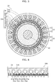
- FIG. 1 is a sectional view of magnetic geared motor 1 according to Embodiment 1.
- magnetic geared motor 1 includes first rotor 10, second rotor 20, and stator 30.
- First rotor 10 is rotated by the magnetomotive force of stator 30, and thus second rotor 20 rotates by a harmonic magnetic flux.
- rotary shaft (shaft) 40 is disposed at the center of first rotor 10.
- first rotor 10 is a high speed rotor that rotates at a higher speed than second rotor 20
- second rotor 20 is a low speed rotor that rotates at a lower speed than first rotor 10.
- Stator 30 opposes first rotor 10 or second rotor 20.
- first rotor 10, second rotor 20, and stator 30 are disposed in this order from the inner side in the radial direction toward the outer side in the radial direction. Therefore, stator 30 opposes second rotor 20.
- first rotor 10, which is a high speed rotor is disposed at an innermost position
- second rotor 20, which is a low speed rotor is disposed so as to surround first rotor 10
- stator 30 is disposed so as to surround second rotor 20.
- second rotor 20 is disposed so as to be sandwiched by first rotor 10 and stator 30.
- First rotor 10, second rotor 20, and stator 30 are disposed coaxial to each other with a small air gap provided therebetween.
- first rotor 10, second rotor 20, and stator 30 are disposed in this order from the inner side in the radial direction toward the outer side in the radial direction. Therefore, an air gap is present between first rotor 10 and second rotor 20, and another air gap is present between second rotor 20 and stator 30.
- First rotor 10 (a first rotor), which is a high speed rotor, includes a plurality of magnetic pole pairs 11 disposed in the circumferential direction.
- first rotor 10 includes cylindrical rotor core 12 formed of a magnetic material, and the plurality of magnetic pole pairs 11 are provided on rotor core 12.
- Rotor core 12 is formed of a plurality of electromagnetic steel plates stacked on top of each other, for example.
- the plurality of magnetic pole pairs 11 are each a permanent magnet and are arranged such that the N-pole and the S-pole appear evenly in an alternating manner along the circumferential direction of rotor core 12.
- the plurality of magnetic pole pairs 11 (the permanent magnets) are disposed continuously in the circumferential direction so as to cover the entire outer peripheral surface of rotor core 12.
- the plurality of magnetic pole pairs 11 are disposed radially about the center axis of first rotor 10.
- the plurality of magnetic pole pairs 11 oppose second rotor 20. Therefore, the surface of the permanent magnet constituting each magnetic pole pair 11 serves as an air gap surface.
- the number of the pole pairs (Nh) of the plurality of magnetic pole pairs 11 is 5. Therefore, the number of the poles of first rotor 10, which is a high speed rotor, is 10.
- Second rotor 20 (a second rotor), which is a low speed rotor, includes a plurality of magnetic pole pieces 21 (pole pieces) disposed in the circumferential direction.
- the plurality of magnetic pole pieces 21 serve as a magnetic flux concentration means formed of a magnetic material.
- second rotor 20 includes annular holder 22 formed of a non-magnetic material, and the plurality of magnetic pole pieces 21 are held in holder 22.
- the plurality of magnetic pole pieces 21 are disposed at a regular interval along the circumferential direction of holder 22.
- the plurality of magnetic pole pieces 21 are disposed radially about the center axis of second rotor 20.
- second rotor 20 includes 41 magnetic pole pieces 21. Therefore, the number of the pole pairs (Nl) of second rotor 20, which is a low speed rotor, is 41.
- the plurality of magnetic pole pieces 21 oppose magnetic pole pairs 11 of first rotor 10.
- the plurality of magnetic pole pieces 21 oppose teeth 31 and a plurality of magnets 34 of stator 30.
- the surface of the plurality of magnetic pole pieces 21 serves as an air gap surface.
- a first surface of each magnetic pole piece 21 where magnetic pole piece 21 opposes first rotor 10 (the surface on the outer side in the radial direction)
- a second surface of each magnetic pole piece 21 where magnetic pole piece 21 opposes stator 30 each serve as an air gap surface.
- second rotor 20 may be a gear-shaped magnetic body formed such that the plurality of magnetic pole pieces 21 each project toward stator 30.
- second rotor 20 can be manufactured of gear-shaped electromagnetic steel plates stacked on top of each other.
- Stator 30 (a stator) produces a magnetomotive force.
- Stator 30 includes a plurality of teeth 31, yoke 32, winding coils 33, and magnets 34.
- the plurality of teeth 31 are disposed along the circumferential direction. Specifically, the plurality of teeth 31 are disposed at a regular interval along the circumferential direction.
- stator 30 includes 24 teeth 31.
- each tooth 31 projects from annular yoke 32 and extends toward the inner side in the radial direction.
- yoke 32 is a back yoke formed on the outer side of teeth 31.
- the plurality of teeth 31 oppose the plurality of magnetic pole pieces 21 of second rotor 20.
- teeth 31 and yoke 32 are integrated into a unit that serves as a stator core.
- teeth 31 and yoke 32 are formed of a plurality of electromagnetic steel plates stacked on top of each other.
- Teeth 31 are each a magnetic pole tooth formed on the inner side of yoke 32 and are each an electromagnet that produces a magnetic force upon the electricity passing through corresponding winding coil 33.
- Winding coils 33 are each a stator coil provided in stator 30. In the present embodiment, winding coil 33 is a concentrated winding coil wound around each of the plurality of teeth 31. In addition, winding coil 33 is a three-phase winding so that first rotor 10 can be rotated as a three-phase synchronous motor. In this example, winding coil 33 may be wound around each tooth 31 with an insulator (not illustrated) provided therebetween.
- a slot for disposing winding coil 33 therein is formed between each two adjacent teeth 31.
- the slots in stator 30 correspond to the respective spaces between each two adjacent teeth 31.
- stator 30 includes 24 teeth 31, and thus the number of the slots in stator 30 is 24. In other words, the number of the pole pairs (Ns) of stator 30 is 24.
- the plurality of teeth 31 each include magnetic pole portion 31a that projects in the radial direction.
- recess portion 31b is provided in each widthwise end of the leading end portion of each tooth 31.
- two recess portions 31b are provided in each tooth 31.
- Magnetic pole portion 31a is formed into a projection as two recess portions 31b are provided in each tooth 31.
- slot opening 31c is present between each two adjacent teeth 31.
- Slot opening 31c is a space present between the leading end portions of two adjacent teeth 31.
- a plurality of magnets 34 (stator magnets) of different polarities are disposed in each slot opening 31c.
- the plurality of magnets 34 that are disposed in each slot opening 31c are disposed so as to close off corresponding slot opening 31c.
- the plurality of magnets 34 are stator magnets disposed in stator 30.
- the plurality of magnets 34 disposed in each slot opening 31c are disposed between magnetic pole portion 31a of one of two adjacent teeth 31 and magnetic pole portion 31a of the other of two adjacent teeth 31.
- the plurality of magnets 34 are each, for example, a permanent magnet.
- the plurality of magnets 34 include at least first magnet 34a and second magnet 34b.
- two permanent magnets serving as first magnet 34a and second magnet 34b are disposed in each slot opening 31c.
- Magnetic pole portions 31a and magnets 34 oppose the plurality of magnetic pole pieces 21 of second rotor 20.
- the front end surface of each magnetic pole portion 31a and the surface of each magnet 34 constitute an air gap surface of stator 30.
- magnetic pole portions 31a, first magnets 34a, and second magnets 34b are disposed continuously with no gap provided therebetween, and thus the front end surfaces of magnetic pole portions 31a, the surfaces of first magnets 34a, and the surfaces of second magnets 34b are flush with each other and form a continuous air gap surface.
- First magnet 34a and second magnet 34b have different polarities in their respective air gap surfaces that oppose second rotor 20.
- first magnet 34a is a permanent magnet whose N-pole lies along its air gap surface that opposes second rotor 20
- second magnet 34b is a permanent magnet whose S-pole lies along its air gap surface that opposes second rotor 20.
- a plurality of magnets 34 having two orientation directions are disposed in each slot opening 31c.
- the plurality of magnets 34 that are disposed in each slot opening 31c are disposed in two recess portions 31b provided in each tooth 31. Specifically, in each tooth 31, first magnet 34a is housed in recess portion 31b provided in one widthwise end of the leading end portion of tooth 31, and second magnet 34b is housed in recess portion 31b provided in the other widthwise end of the leading end portion of tooth 31.
- the number of the sets of magnets 34 in each slot opening 31c is equal to the number of the slots in stator 30.
- the number of first magnets 34a and the number of second magnets 34b are each equal to the number of the slots in stator 30.
- the number of the slots in stator 30 is 24. Therefore, stator 30 as a whole includes 24 first magnets 34a and 24 second magnets 34b disposed therein.
- stator 30 includes 24 teeth 31, 24 sets of magnetic pole portion 31a of tooth 31, first magnet 34a, and second magnet 34b are disposed cyclically.
- FIG. 2 schematically illustrates the distribution of polarities along the circumferential direction of stator 30 of magnetic geared motor 1 according to
- magnetic pole portions 31a, first magnets 34a, and second magnets 34b are disposed such that the N-pole and the S-pole appear in an alternating manner in the air gap surface.
- first magnet 34a has the polarity that causes the N-pole to appear on its air gap surface
- second magnet 34b has the polarity that causes the S-pole to appear on its air gap surface. Therefore, as illustrated in FIG.
- first magnet 34a N-pole
- second magnet 34b S-pole
- magnetic pole portion 31a N-pole
- second magnet 34b S-pole
- first magnet 34a N-pole
- magnetic pole portion 31a S-pole
- magnetic pole portion 31a S-pole
- first rotor 10 rotates by the magnetomotive force of winding coils 33 in stator 30. Specifically, upon the electricity passing through winding coils 33 in stator 30, a field current flows through winding coils 13, and a magnetic flux is produced in each tooth 31 (magnetic pole portion 31a). The magnetic force produced through the interaction between the magnetic flux produced in each tooth 31 and the magnetic flux produced from each magnetic pole pair 11 of first rotor 10 (the high speed rotor) functions as the torque that causes first rotor 10 to rotate, and thus first rotor 10 rotates. Then, as first rotor 10 rotates, second rotor 20 having an output shaft is decelerated due to a harmonic magnetic flux in accordance with a predetermined gear ratio (moderating ratio), and second rotor 20 rotates accordingly.
- moderating ratio moderating ratio
- the magnetic flux produced inside a magnetic reduction gear is expressed by the product of the magnetomotive force of a permanent magnet and the permeance of a magnetic body.
- the magnetic flux produced inside magnetic geared motor 1 will be considered based on some mathematical expressions.
- a 1 and A 2 denote, respectively, the amplitude of the magnetomotive force produced by first rotor 10 (the high speed rotor) and the amplitude of the magnetomotive force produced by the magnets (the permanent magnets) in stator 30;
- N h denotes the number of the pole pairs of first rotor 10;
- N s denotes the number of the slots in stator 30;
- ⁇ denotes the angle of rotation of first rotor 10 (the high speed rotor); and ⁇ denotes the position in the circumferential direction.
- Permeance distribution P( ⁇ , ⁇ ) of the magnetic bodies present in second rotor 20, which is a low speed rotor, and stator 30 is expressed by Expression 2 indicated below, with the assumption that permeance distribution P( ⁇ , ⁇ ) extends in a sinusoidal wave form in the circumferential direction.
- P 0 denotes the mean permeance
- P 1 and P 2 denote, respectively, the amplitude of the permeance of second rotor 20 (the low speed rotor) and the amplitude of the permeance of stator 30
- N l denotes the number of the poles of second rotor 20 (the low speed rotor)
- ⁇ denotes the angle of rotation of second rotor 20 (the low speed rotor).
- magnetic flux ⁇ ( ⁇ , ⁇ , ⁇ ) produced inside magnetic geared motor 1 is expressed by the product of Expression 1 and Expression 2 and is thus expressed by Expression 3 indicated below.
- the first term and the second term indicate the fundamental wave magnetic flux of the order identical to the number of the poles of magnets 34, and the third term and thereafter indicate the modulated magnetic flux produced through the combination with the magnetic bodies.
- the combinations of the numbers of the poles where the relationship indicated by Expression 4 below is satisfied are employed.
- positive gear ratio G r indicates that first rotor 10 (the high speed rotor) and second rotor 20 (the low speed rotor) rotate in the same direction
- negative gear ratio G r indicates that first rotor 10 (the high speed rotor) and second rotor 20 (the low speed rotor) rotate in the opposite directions.
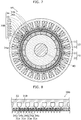
- FIG. 3 is a sectional view of magnetic geared motor 1X according to the comparative example
- FIG. 4 schematically illustrates the distribution of polarities in the circumferential direction of stator 30X of magnetic geared motor 1X.
- magnetic geared motor 1X differs from magnetic geared motor 1 illustrated in FIG. 1 in terms of the configuration of magnet 34X disposed in each slot opening 31c.
- each slot opening 31c in magnetic geared motor 1 a plurality of magnets 34 of different polarities are disposed in each slot opening 31c in magnetic geared motor 1 according to the present embodiment
- one magnet 34X is disposed in each slot opening 31c in magnetic geared motor 1X according to the comparative example, as illustrated in FIG. 3 .
- magnetic pole portions 31a of teeth 31 and magnets 34X are disposed such that the N-pole and the S-pole appear in an alternating manner in the air gap surface.
- the plurality of magnets 34X disposed in stator 30X have the same polarity in their air gap surfaces, and the plurality of magnetic pole portions 31a of stator 30X also have the same polarity in their air gap surfaces.
- all magnets 34X have the N-pole in their air gap surfaces
- all magnetic pole portions 31a have the S-pole in their air gap surfaces
- the sequence where magnet 34X (N-pole) is followed by magnetic pole portion 31a (S-pole) is repeated.
- magnetic geared motor 1X In magnetic geared motor 1X according to the comparative example configured as described above, the order of the magnetomotive force produced by magnets 34X in stator 30X (the order of the stator magnet magnetomotive force) is 24, which is the same as the number of the slots in stator 30X.
- magnetic geared motor 1 a plurality of magnets 34 of different polarities are disposed in each slot opening 31c. Specifically, two permanent magnets of different polarities, namely first magnet 34a and second magnet 34b, are disposed in each slot opening 31c.
- This configuration allows the order of the magnetomotive force produced by magnets 34 in stator 30 of magnetic geared motor 1 according to the present embodiment to increase by one and a half times as compared to the order of the counterpart in magnetic geared motor 1X according to the comparative example.
- the order of the magnetomotive force produced by magnets 34 in stator 30 (the order of the stator magnet magnetomotive force) is 36.
- magnetic geared motor 1 As described above, magnetic geared motor 1 according to the present embodiment makes it possible to obtain a high gear ratio, and high torque magnetic geared motor 1 can be achieved.
- FIG. 5 is a sectional view of magnetic geared motor 1A according to Embodiment 2
- FIG. 6 schematically illustrates the distribution of polarities in the circumferential direction of stator 30A of magnetic geared motor 1A.
- magnetic geared motor 1A includes first rotor 10, second rotor 20, and stator 30A.
- First rotor 10, second rotor 20, and stator 30A are disposed coaxial to each other.
- stator 30A includes a plurality of teeth 31A, yoke 32, winding coils 33, and a plurality of magnets 34.
- Magnetic geared motor 1A according to the present embodiment differs from magnetic geared motor 1 according to Embodiment 1 described above in terms of the configuration of magnetic pole portions 31a of teeth 31A.
- each magnetic pole portion 31a is provided in each of the plurality of teeth 31 in Embodiment 1 described above, a plurality of magnetic pole portions 31a are provided for each of the plurality of teeth 31A in the present embodiment.
- the plurality of magnetic pole portions 31a are formed into a gear shape, and each magnetic pole portion 31a serves as a small tooth in tooth 31A.
- each tooth 31A is provided with one recess portion 31b at the middle of the leading end portion of tooth 31A and two recess portions 31b at respective widthwise ends of the leading end portion of tooth 31A (i.e., three recess portions 31b), and thus each tooth 31A is provided with two magnetic pole portions 31a.
- each magnetic pole portion 31a projects in the radial direction.
- magnetic geared motor 1A differs from magnetic geared motor 1 according to Embodiment 1 described above in terms of the arrangement of the plurality of magnets 34 disposed in stator 30A.
- the plurality of magnets 34 include first magnet 34a disposed in slot opening 31c present between two adjacent teeth 31A and second magnet 34b disposed between two adjacent magnetic pole portions 31a in each of the plurality of teeth 31A.
- one first magnet 34a is disposed in each slot opening 31c. Specifically, one first magnet 34a is housed in a recess portion formed by recess portion 31b in one of two adjacent teeth 31A and recess portion 31b in the other one of two adjacent teeth 31A.
- second magnet 34b is disposed in each tooth 31A. Specifically, second magnet 34b is housed in recess portion 31b provided at the widthwise middle of the leading end portion of each tooth 31A.
- Magnetic pole portions 31a and magnets 34 oppose the plurality of magnetic pole pieces 21 of second rotor 20.
- the front end surface of each magnetic pole portion 31a and the surface of each magnet 34 constitute an air gap surface of stator 30A.
- magnetic pole portions 31a, first magnets 34a, and second magnets 34b are disposed continuously with no gap provided therebetween, and thus the front end surfaces of magnetic pole portions 31a, the surfaces of first magnets 34a, and the surfaces of second magnets 34b are flush with each other and form a continuous air gap surface.
- magnetic geared motor 1A differs from magnetic geared motor 1 according to Embodiment 1 described above in terms of the polarities of the plurality of magnets 34 (first magnets 34a and second magnets 34b).
- first magnet 34a and second magnet 34b are arrayed in the circumferential direction such that the opposite polarities appear in an alternating manner in Embodiment 1 described above
- first magnet 34a and second magnet 34b are arrayed in the circumferential direction such that first magnet 34a and second magnet 34b have the same polarity in the present embodiment.
- first magnets 34a and second magnets 34b have the same polarity in their respective air gap surfaces that oppose second rotor 20. In this manner, in the present embodiment, all magnets 34 have the same polarity, and first magnets 34a and second magnets 34b have the same orientation.
- first magnets 34a and second magnets 34b where first magnets 34a and second magnets 34b oppose second rotor 20 are all the N-pole.
- the entire plurality of magnets 34 including first magnets 34a and second magnets 34b are disposed at a regular interval in the circumferential direction.
- first magnets 34a and second magnets 34b are each a permanent magnet.
- the number of the plurality of magnets 34 is twice the number of the slots in stator 30A. Specifically, since the number of the slots in stator 30A is 24, 48 magnets 34 are used. To be more specific, 24 first magnets 34a corresponding to respective slot openings 31c and 24 second magnets 34b corresponding to respective teeth 31A are used.
- FIG. 6 schematically illustrates the distribution of polarities in the circumferential direction of stator 30A of magnetic geared motor 1A according to Embodiment 2.
- magnetic pole portions 31a and magnets 34 are disposed such that the N-pole and the S-pole appear in an alternating manner in the air gap surface.
- magnets 34 first magnets 34a and second magnets 34b
- magnets 34 have the polarity that causes the N-pole to appear in their air gap surface. Therefore, as illustrated in FIG. 6 , for example, the sequence consisting of first magnet 34a (N-pole), magnetic pole portion 31a (S-pole), second magnet 34b (N-pole), magnetic pole portion 31a (S-pole), first magnet 34a (N-pole), and magnetic pole portion 31a (S-pole) in this order is repeated in stator 30A.
- first rotor 10 which is a high speed rotor, is identical to first rotor 10 according to Embodiment 1 described above. Specifically, in the present embodiment as well, the number of the pole pairs (Nh) of the plurality of magnetic pole pairs 11 of first rotor 10 is 5, and the number of the poles of first rotor 10 is 10.
- second rotor 20 which is a low speed rotor, includes a plurality of magnetic pole pieces 21.
- the number of the plurality of magnetic pole pieces 21 in the present embodiment differs from the number of the plurality of magnetic pole pieces 21 in Embodiment 1.
- second rotor 20 according to the present embodiment includes 53 magnetic pole pieces 21, and the number of the pole pairs (Nl) of second rotor 20 is 53.
- Magnetic geared motor 1A configured as described above can increase the order of the magnetomotive force produced by magnets 34 in stator 30A by twofold.
- the order of the magnetomotive force produced by magnets 34 in stator 30A (the order of the stator magnet magnetomotive force) is 48. This makes it possible to increase the gear ratio by increasing the number of the pole pairs of magnetic pole pieces 21 of second rotor 20, and thus the torque density can be increased.
- magnetic geared motor 1A also makes it possible to obtain a high gear ratio, and high torque magnetic geared motor 1A can be achieved.
- the number of the plurality of magnets 34 is twice the number of the slots in stator 30A, but this is not a limiting example.
- the number of the plurality of magnets 34 may be three times the number of the slots in stator 30B. Specifically, since the number of the slots in stator 30B is 24, 72 magnets 34 are used.
- magnetic pole portions 31a of teeth 31B and magnets 34 are arrayed in the circumferential direction such that the opposite polarities appear in an alternating manner.
- second rotor 20 includes 77 magnetic pole pieces 21 and the number of the pole pairs (Nl) of second rotor 20 is 77.
- Magnetic geared motor 1B configured as described above can increase the order of the magnetomotive force produced by magnets 34 in stator 30B by threefold.
- the order of the magnetomotive force produced by magnets 34 in stator 30B is 72. This makes it possible to increase the gear ratio by increasing the number of the pole pairs of magnetic pole pieces 21 of second rotor 20, and thus the torque density can be increased.
- magnetic geared motor 1B also makes it possible to obtain a high gear ratio, and high torque magnetic geared motor 1B can be achieved.
- the order of the magnetomotive force produced by magnets 34 or 34X disposed in the stator is 24 in Comparative Example, 36 in Example 1, 48 in Example 2, and 72 in Example 3. Meanwhile, gear ratio Gr is 5.8 in Comparative Example, 8.2 in Example 1, 10.6 in Example 2, and 15.4 in Example 3.
- FIG. 9 illustrates the back electromotive force constants (back EMF constants) in Comparative Example, Example 1, Example 2, and Example 3.
- FIG. 9 shows that the back electromotive force constant increases in accordance with an increase in the gear ratio.
- FIG. 10 shows the main magnetic flux (fifth order) and the modulated magnetic flux in the air gap on the side of the stator in each of Comparative Example, Example 1, Example 2, and Example 3.
- the vertical axis represents the magnetic flux density.
- FIG. 10 shows that the main magnetic flux (fifth order) is produced in each of Comparative Example, Example 1, Example 2, and Example 3 as well as that the harmonic magnetic flux corresponding to the order of the stator magnet magnetomotive force is produced in each of Comparative Example, Example 1, Example 2, and Example 3.
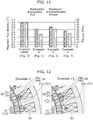
- FIG. 11 shows the modulated magnetic flux and the maximum transmission torque in each of Comparative Example, Example 1, Example 2, and Example 3. It is to be noted that the modulated magnetic flux is indicated by the magnetic flux density.
- FIG. 11 shows that there is a correlation between the amplitude of the modulated magnetic flux and the magnitude of the pull-out torque except in Example 1.
- Example 1 a factor or factors causing the low pull-out torque in Example 1 were evaluated, and it was found that the volume of the stator core in stator 30 was large with respect to one magnet 34 and that the positional deviation of the center of the magnetic pole caused a mismatch between the modulated magnetic flux of the first rotor (the high speed rotor) and the phase of the magnetomotive force produced by stator 30.
- the volume of magnet 34 (the stator magnet) was adjusted in magnetic geared motor 1 according to Example 1, and a magnetic geared motor in which the centers of the magnetic poles were positioned at a regular interval (Example 1') was conceived.
- first magnet 34a and second magnet 34b each have a larger width
- first magnet 34a, second magnet 34b, and magnetic pole portion 31a have substantially the same width.
- FIGS. 13A and 13B show the characteristics of Example 1 and Example 1' obtained in this case.
- FIG. 13A shows the main magnetic flux (fifth order) and the modulated magnetic flux in each of Example 1 and Example 1'.
- FIG. 13B shows the back electromotive force constant and the maximum transmission torque in each of Example 1 and Example 1'.
- the modulated magnetic flux of first rotor 10 matches the phase of the magnetomotive force produced by stator 30, and the volume of magnet 34 (the stator magnet) is larger in the magnetic geared motor according to Example 1' than in the magnetic geared motor according to Example 1.
- the pull-out torque can be increased in the magnetic geared motor according to Example 1'.
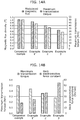
- Example 1 is replaced with Example 1' in FIG. 11 , and the result is sorted out accordingly. Then, the result shown in FIG. 14A is obtained.
- FIG. 14A shows the modulated magnetic flux and the maximum transmission torque in each of Comparative Example, Example 1', Example 2, and Example 3. It is to be noted that the modulated magnetic flux is indicated by the magnetic flux density.
- FIG. 14B shows the maximum transmission torque and the back electromotive force constant in each of Comparative Example, Example 1', Example 2, and Example 3.
- FIG. 14A shows that the modulated magnetic flux and the maximum transmission torque decrease in accordance with an increase in the gear ratio in each of Comparative Example, Example 1', Example 2, and Example 3.
- FIG. 14B shows that the back electromotive force constant rises in accordance with an increase in the gear ratio in each of Comparative Example, Example 1', Example 2, and Example 3.
- FIGS. 15 , 16 , and 17 show the combinations of the number of the magnetic poles in the high speed rotor (first rotor 10) and the number of the slots in stator 30 but do not show the number of the magnetic poles in the low speed rotor (second rotor 20).
- the number of the magnetic poles in the low speed rotor (second rotor 20) can be determined if the high speed rotor (first rotor 10) and the number of the slots in stator 30 are determined and is thus not shown in FIGS. 15 , 16 , and 17 .
- the blanks in FIGS. 15 , 16 , and 17 each indicate a combination that is not possible as a motor.
- FIG. 15 the result of the presence or the absence of geometric symmetry between the high speed rotor (first rotor 10) and stator 30 is as shown in FIG. 15 .
- a circle indicates a combination in which the high speed rotor (first rotor 10) and stator 30 are geometrically symmetric and the high speed rotor rotates non-eccentrically.
- an "x" indicates a combination in which the high speed rotor (first rotor 10) and stator 30 are not geometrically symmetric and the high speed rotor may rotate eccentrically.
- the result shown in FIG. 17 reveals that mainly a 10 pole 24 slot combination and an 8 pole 18 slot combination, in which the value of the winding factor ⁇ the gear ratio is large, are to be evaluated.
- the magnetomotive force obtained by magnets 34 (the stator magnets) disposed in the stator having concentrated winding coils can be increased by one and a half times (Example 1, Example 1'), by two times (Example 2), or by three times (Example 3) relative to the magnetic geared motor according to Comparative Example, and a magnetic geared motor having a high gear ratio can be achieved.
- an increased gear ratio leads to a decrease in the amplitude of the modulated magnetic flux and in the pull-out torque as well as an increase in the back electromotive force constant.
- magnetic pole portions 31a of two adjacent teeth 31 have different polarities, and thus a loop of a magnetic flux is produced via yoke 32, as illustrated in the left drawing in FIG. 18 .
- This causes the magnetic flux produced by first rotor 10, which is a high speed rotor, to enhance the magnetic flux produced by magnets 34, and this can more easily produce magnetic saturation in teeth 31 by magnets 34.
- slot opening 31c (an air gap) may be filled with magnetic member 35, as in stator 30C illustrated in the right drawing in FIG. 18 .
- This configuration makes it possible to form a path for the magnetic flux by magnetic member 35, and thus the magnetic flux passing through yoke 32 can be reduced.
- slot opening 31c may be filled by connecting two adjacent teeth 31.
- a plurality of magnets 34 of two orientations are disposed in slot opening 31c, but this is not a limiting example.
- a plurality of magnets 34 of two or more orientations may be disposed in slot opening 31c.
- first rotor 10, second rotor 20, and stator 30, 30A or 30B are disposed in this order from the inner side in the radial direction toward the outer side in the radial direction, but this is not a limiting example.
- first rotor 10, stator 30, 30A, or 30B, and second rotor 20 may be disposed in this order from the inner side in the radial direction toward the outer side in the radial direction, or stator 30, 30A, or 30B, first rotor 10, and second rotor 20 may be disposed in this order from the inner side in the radial direction toward the outer side in the radial direction.
- first rotor 10, second rotor 20, and stator 30, 30A or 30B may be disposed in any other order.
- a concentrated winding coil is used as winding coil 33 in stator 30, 30A, 30B or 30C, but this is not a limiting example.
- a distributed winding coil may be used as winding coil 33.
- a flux barrier may be provided at a border portion where the polarity changes.
- a flux barrier may be provided between magnetic pole portion 31a and magnet 34 (first magnet 34a or second magnet 34b).
- a flux barrier may be provided between first magnet 34a and second magnet 34b as well. It is to be noted that a flux barrier may be a space (an air layer) or a filler member or the like formed of a non-magnetic material.
- the present disclosure can be used in various electrical apparatuses, including an AGV.
Landscapes
- Engineering & Computer Science (AREA)
- Power Engineering (AREA)
- Connection Of Motors, Electrical Generators, Mechanical Devices, And The Like (AREA)
- Iron Core Of Rotating Electric Machines (AREA)
- Permanent Field Magnets Of Synchronous Machinery (AREA)
- Permanent Magnet Type Synchronous Machine (AREA)
Applications Claiming Priority (2)
| Application Number | Priority Date | Filing Date | Title |
|---|---|---|---|
| JP2019033390 | 2019-02-26 | ||
| PCT/JP2020/001826 WO2020174936A1 (fr) | 2019-02-26 | 2020-01-21 | Moteur à engrenage magnétique |
Publications (2)
| Publication Number | Publication Date |
|---|---|
| EP3934072A1 true EP3934072A1 (fr) | 2022-01-05 |
| EP3934072A4 EP3934072A4 (fr) | 2022-04-06 |
Family
ID=72238435
Family Applications (1)
| Application Number | Title | Priority Date | Filing Date |
|---|---|---|---|
| EP20762670.6A Pending EP3934072A4 (fr) | 2019-02-26 | 2020-01-21 | Moteur à engrenage magnétique |
Country Status (5)
| Country | Link |
|---|---|
| US (1) | US11979072B2 (fr) |
| EP (1) | EP3934072A4 (fr) |
| JP (1) | JP7361344B2 (fr) |
| CN (1) | CN113169647B (fr) |
| WO (1) | WO2020174936A1 (fr) |
Cited By (2)
| Publication number | Priority date | Publication date | Assignee | Title |
|---|---|---|---|---|
| EP4096062A4 (fr) * | 2020-01-21 | 2023-01-18 | Mitsubishi Electric Corporation | Stator et machine électrique rotative utilisant celui-ci |
| FR3163785A1 (fr) * | 2024-06-25 | 2025-12-26 | Safran Landing Systems | Machine électrique à cales aimantées |
Families Citing this family (17)
| Publication number | Priority date | Publication date | Assignee | Title |
|---|---|---|---|---|
| US11979072B2 (en) * | 2019-02-26 | 2024-05-07 | Panasonic Intellectual Property Management Co., Ltd. | Magnetic geared motor |
| WO2021210119A1 (fr) * | 2020-04-16 | 2021-10-21 | 三菱電機株式会社 | Moteur à engrenage magnétique |
| CN116134246B (zh) * | 2020-08-03 | 2025-07-01 | 三菱电机株式会社 | 磁通调制型磁力齿轮 |
| JPWO2022118598A1 (fr) * | 2020-12-02 | 2022-06-09 | ||
| KR102769948B1 (ko) * | 2020-12-07 | 2025-02-17 | 현대자동차주식회사 | 마그네틱 기어 |
| EP4270745A4 (fr) * | 2020-12-23 | 2024-02-28 | Mitsubishi Electric Corporation | Machine électrique rotative de type à aimant permanent |
| JP7595496B2 (ja) * | 2021-03-22 | 2024-12-06 | 三菱重工業株式会社 | 磁気ギアード回転機械、及び発電システム |
| JP7615854B2 (ja) * | 2021-04-13 | 2025-01-17 | 株式会社デンソー | 駆動伝達装置 |
| JP7216156B1 (ja) * | 2021-07-27 | 2023-01-31 | 三菱重工業株式会社 | 磁気ギアード電気機械、発電システム、及び駆動システム |
| JP7090828B1 (ja) | 2021-11-18 | 2022-06-24 | 三菱電機株式会社 | 永久磁石式回転電機 |
| US20250007380A1 (en) * | 2021-12-01 | 2025-01-02 | Mitsubishi Electric Corporation | Rotor and magnetic wave gear device |
| JP7317267B1 (ja) * | 2022-04-14 | 2023-07-28 | 三菱電機株式会社 | 回転装置 |
| JP7829446B2 (ja) * | 2022-08-19 | 2026-03-13 | 三菱重工業株式会社 | 可変速動力装置及び制御方法 |
| WO2024148115A1 (fr) * | 2023-01-04 | 2024-07-11 | Fluxworks, Inc. | Couplages magnétiques |
| CN121058145A (zh) * | 2023-03-01 | 2025-12-02 | 靛蓝技术股份有限公司 | 用于电动马达的定子及其组装方法 |
| JPWO2024262571A1 (fr) * | 2023-06-21 | 2024-12-26 | ||
| WO2026014084A1 (fr) * | 2024-07-11 | 2026-01-15 | パナソニックIpマネジメント株式会社 | Moteur sans palier à engrenage magnétique |
Family Cites Families (33)
| Publication number | Priority date | Publication date | Assignee | Title |
|---|---|---|---|---|
| JP2000060091A (ja) * | 1998-08-06 | 2000-02-25 | Ebara Corp | 回転電機 |
| US6359366B1 (en) * | 2000-05-09 | 2002-03-19 | Ford Global Technologies, Inc. | Hybrid permanent magnet/synchronous machines |
| GB2437568B (en) * | 2006-04-24 | 2009-02-11 | Univ Sheffield | Electrical machines |
| JP5045067B2 (ja) | 2006-11-10 | 2012-10-10 | 株式会社明電舎 | ベアリングレスモータに適用した順突極モータ |
| GB0800463D0 (en) * | 2008-01-11 | 2008-02-20 | Magnomatics Ltd | Magnetic drive systems |
| GB0813173D0 (en) * | 2008-02-21 | 2008-08-27 | Magnomatics Ltd | Wind turbine power train |
| GB0810096D0 (en) * | 2008-06-03 | 2008-07-09 | Magnomatics Ltd | Electrical machines |
| GB0807388D0 (en) * | 2008-04-23 | 2008-05-28 | Magnomatics Ltd | Electrical machines |
| GB2468888B (en) * | 2009-03-26 | 2013-11-06 | Magnomatics Ltd | Marine propulsion device with an electrical machine having integral magnetic gearing |
| CN102104303B (zh) * | 2011-01-07 | 2012-11-28 | 东南大学 | 一种基于磁齿轮的盘式低速大转矩复合电机 |
| EP2528207A1 (fr) | 2011-05-23 | 2012-11-28 | Delphi Automotive Systems Luxembourg SA | Machine électrique sans balai |
| JP5723987B2 (ja) * | 2011-06-27 | 2015-05-27 | 株式会社日立製作所 | 磁気歯車型回転電機 |
| JP2013059178A (ja) * | 2011-09-07 | 2013-03-28 | Mitsubishi Electric Corp | 磁気ギア |
| JP5858399B2 (ja) | 2011-11-11 | 2016-02-10 | 国立大学法人大阪大学 | 磁気減速機構及び低速ロータ磁気減速回転制御方法 |
| JP6093592B2 (ja) * | 2013-02-22 | 2017-03-08 | 株式会社Ihi | 磁気波動歯車装置 |
| JP6072606B2 (ja) * | 2013-05-20 | 2017-02-01 | 株式会社豊田中央研究所 | 回転電機 |
| CN108390539B (zh) * | 2014-02-11 | 2020-07-17 | 马格诺麦克斯有限公司 | 磁齿轮系统和用于减小扭矩脉动传送的方法 |
| US9641059B2 (en) * | 2014-02-21 | 2017-05-02 | The University Of North Carolina At Charlotte | Flux focusing magnetic gear assembly using ferrite magnets or the like |
| JP6265569B2 (ja) * | 2014-03-12 | 2018-01-24 | 株式会社Ihi | 環状磁極部材及び磁気波動歯車装置 |
| EP3147542B1 (fr) * | 2014-05-20 | 2020-02-12 | IHI Corporation | Dispositif d'engrenage à ondes magnétiques |
| JP6403329B2 (ja) * | 2015-01-20 | 2018-10-10 | 株式会社Ihi | 磁気波動歯車装置 |
| GB2545154B (en) | 2015-08-24 | 2021-12-01 | Magnomatics Ltd | Magnetically geared apparatus and a pole piece for such apparatus |
| JP6327221B2 (ja) * | 2015-09-04 | 2018-05-23 | マツダ株式会社 | 回転電機 |
| GB2549448A (en) * | 2016-01-13 | 2017-10-25 | Magnomatics Ltd | A magnetically geared apparatus |
| JP6595443B2 (ja) * | 2016-12-01 | 2019-10-23 | トヨタ自動車株式会社 | 回転電機 |
| CN108011484B (zh) * | 2017-12-11 | 2020-08-18 | 华中科技大学 | 一种磁齿轮复合电机 |
| US11979072B2 (en) * | 2019-02-26 | 2024-05-07 | Panasonic Intellectual Property Management Co., Ltd. | Magnetic geared motor |
| JP7409882B2 (ja) * | 2020-01-16 | 2024-01-09 | 三菱重工業株式会社 | 磁界発生装置、及び、磁気歯車 |
| WO2021149130A1 (fr) * | 2020-01-21 | 2021-07-29 | 三菱電機株式会社 | Stator et machine électrique tournante l'utilisant |
| JP7263561B2 (ja) * | 2020-01-24 | 2023-04-24 | 三菱重工業株式会社 | 磁気歯車の磁極片装置、磁気歯車、及び、磁気歯車の磁極片装置の製造方法 |
| US12500498B2 (en) * | 2020-04-16 | 2025-12-16 | Mitsubishi Electric Corporation | Rotary electric machine |
| JP7357805B2 (ja) * | 2020-09-07 | 2023-10-06 | 三菱電機株式会社 | 回転電機および固定子の製造方法 |
| JP7527493B2 (ja) * | 2021-08-02 | 2024-08-02 | 三菱電機株式会社 | 磁気波動歯車装置 |
-
2020
- 2020-01-21 US US17/296,511 patent/US11979072B2/en active Active
- 2020-01-21 JP JP2021501724A patent/JP7361344B2/ja active Active
- 2020-01-21 CN CN202080006381.8A patent/CN113169647B/zh active Active
- 2020-01-21 EP EP20762670.6A patent/EP3934072A4/fr active Pending
- 2020-01-21 WO PCT/JP2020/001826 patent/WO2020174936A1/fr not_active Ceased
Cited By (4)
| Publication number | Priority date | Publication date | Assignee | Title |
|---|---|---|---|---|
| EP4096062A4 (fr) * | 2020-01-21 | 2023-01-18 | Mitsubishi Electric Corporation | Stator et machine électrique rotative utilisant celui-ci |
| US12176756B2 (en) | 2020-01-21 | 2024-12-24 | Mitsubishi Electric Corporation | Stator with stator magnet, magnetic body, fixing member, and coil disposed in slots and rotary electric machine using same |
| FR3163785A1 (fr) * | 2024-06-25 | 2025-12-26 | Safran Landing Systems | Machine électrique à cales aimantées |
| WO2026003123A1 (fr) * | 2024-06-25 | 2026-01-02 | Safran Landing Systems | Dispositif de freinage a cales aimantees |
Also Published As
| Publication number | Publication date |
|---|---|
| US20220052596A1 (en) | 2022-02-17 |
| US11979072B2 (en) | 2024-05-07 |
| JP7361344B2 (ja) | 2023-10-16 |
| WO2020174936A1 (fr) | 2020-09-03 |
| CN113169647B (zh) | 2024-05-31 |
| EP3934072A4 (fr) | 2022-04-06 |
| CN113169647A (zh) | 2021-07-23 |
| JPWO2020174936A1 (ja) | 2021-12-23 |
Similar Documents
| Publication | Publication Date | Title |
|---|---|---|
| US11979072B2 (en) | Magnetic geared motor | |
| US11183893B2 (en) | Rotary electric device | |
| EP3118972B1 (fr) | Élément pôle magnétique annulaire, et dispositif d'engrenage à onde magnétique | |
| US6376957B1 (en) | Alternating current machine | |
| US20210218301A1 (en) | Rotating electric machine | |
| US10236732B2 (en) | Inductor type rotary motor | |
| US10020717B2 (en) | Dual stator, flux switching permanent magnet machine | |
| JP2007074870A (ja) | 永久磁石埋込型ロータおよび永久磁石埋込型モータ | |
| JPWO2017171037A1 (ja) | ロータ及びロータの設計方法 | |
| US10811946B1 (en) | Cycloidal reluctance motor with rotor permanent magnets | |
| US20060022553A1 (en) | Rotating electric machine | |
| EP2793379B1 (fr) | Générateur | |
| US20230023710A1 (en) | Synchronous reluctance machine having a variable air gap | |
| JP5919999B2 (ja) | ステータ、回転電機、および電動車両 | |
| US12176754B2 (en) | Electric machine and magnetic field portion | |
| EP3923457A1 (fr) | Moteur à engrenage magnétique | |
| JP2014087127A (ja) | 発電機および発電システム | |
| JP3882949B2 (ja) | 環状コイル式永久磁石型回転電機 | |
| JP7534995B2 (ja) | 回転電機 | |
| JP2805640B2 (ja) | ボビン巻電動機 | |
| JP2019103293A (ja) | モータ | |
| CN116746040A (zh) | 电气机械 | |
| JP2015050901A (ja) | 発電機および発電システム | |
| US20160164352A1 (en) | Electric apparatus including rotor, stator, and shaft | |
| JPS63129851A (ja) | アウタロ−タ型ハイブリツトモ−タの外側ヨ−ク構造 |
Legal Events
| Date | Code | Title | Description |
|---|---|---|---|
| STAA | Information on the status of an ep patent application or granted ep patent |
Free format text: STATUS: THE INTERNATIONAL PUBLICATION HAS BEEN MADE |
|
| PUAI | Public reference made under article 153(3) epc to a published international application that has entered the european phase |
Free format text: ORIGINAL CODE: 0009012 |
|
| STAA | Information on the status of an ep patent application or granted ep patent |
Free format text: STATUS: REQUEST FOR EXAMINATION WAS MADE |
|
| 17P | Request for examination filed |
Effective date: 20210909 |
|
| AK | Designated contracting states |
Kind code of ref document: A1 Designated state(s): AL AT BE BG CH CY CZ DE DK EE ES FI FR GB GR HR HU IE IS IT LI LT LU LV MC MK MT NL NO PL PT RO RS SE SI SK SM TR |
|
| A4 | Supplementary search report drawn up and despatched |
Effective date: 20220304 |
|
| RIC1 | Information provided on ipc code assigned before grant |
Ipc: H02K 7/11 20060101ALI20220228BHEP Ipc: H02K 1/12 20060101ALI20220228BHEP Ipc: H02K 49/10 20060101ALI20220228BHEP Ipc: H02K 1/278 20220101ALI20220228BHEP Ipc: H02K 1/24 20060101ALI20220228BHEP Ipc: H02K 1/17 20060101ALI20220228BHEP Ipc: H02K 1/14 20060101ALI20220228BHEP Ipc: H02K 21/14 20060101ALI20220228BHEP Ipc: H02K 16/02 20060101AFI20220228BHEP |
|
| DAV | Request for validation of the european patent (deleted) | ||
| DAX | Request for extension of the european patent (deleted) | ||
| GRAP | Despatch of communication of intention to grant a patent |
Free format text: ORIGINAL CODE: EPIDOSNIGR1 |
|
| STAA | Information on the status of an ep patent application or granted ep patent |
Free format text: STATUS: GRANT OF PATENT IS INTENDED |
|
| INTG | Intention to grant announced |
Effective date: 20260306 |