EP3934748B1 - Affichage graphique d'informations de débit de dose pour planification de radiothérapie - Google Patents
Affichage graphique d'informations de débit de dose pour planification de radiothérapie Download PDFInfo
- Publication number
- EP3934748B1 EP3934748B1 EP20714452.8A EP20714452A EP3934748B1 EP 3934748 B1 EP3934748 B1 EP 3934748B1 EP 20714452 A EP20714452 A EP 20714452A EP 3934748 B1 EP3934748 B1 EP 3934748B1
- Authority
- EP
- European Patent Office
- Prior art keywords
- volume
- dose
- sub
- dose rate
- histogram
- Prior art date
- Legal status (The legal status is an assumption and is not a legal conclusion. Google has not performed a legal analysis and makes no representation as to the accuracy of the status listed.)
- Active
Links
Images




Classifications
-
- A—HUMAN NECESSITIES
- A61—MEDICAL OR VETERINARY SCIENCE; HYGIENE
- A61N—ELECTROTHERAPY; MAGNETOTHERAPY; RADIATION THERAPY; ULTRASOUND THERAPY
- A61N5/00—Radiation therapy
- A61N5/10—X-ray therapy; Gamma-ray therapy; Particle-irradiation therapy
- A61N5/103—Treatment planning systems
-
- G—PHYSICS
- G16—INFORMATION AND COMMUNICATION TECHNOLOGY [ICT] SPECIALLY ADAPTED FOR SPECIFIC APPLICATION FIELDS
- G16H—HEALTHCARE INFORMATICS, i.e. INFORMATION AND COMMUNICATION TECHNOLOGY [ICT] SPECIALLY ADAPTED FOR THE HANDLING OR PROCESSING OF MEDICAL OR HEALTHCARE DATA
- G16H10/00—ICT specially adapted for the handling or processing of patient-related medical or healthcare data
- G16H10/60—ICT specially adapted for the handling or processing of patient-related medical or healthcare data for patient-specific data, e.g. for electronic patient records
-
- G—PHYSICS
- G16—INFORMATION AND COMMUNICATION TECHNOLOGY [ICT] SPECIALLY ADAPTED FOR SPECIFIC APPLICATION FIELDS
- G16H—HEALTHCARE INFORMATICS, i.e. INFORMATION AND COMMUNICATION TECHNOLOGY [ICT] SPECIALLY ADAPTED FOR THE HANDLING OR PROCESSING OF MEDICAL OR HEALTHCARE DATA
- G16H15/00—ICT specially adapted for medical reports, e.g. generation or transmission thereof
-
- G—PHYSICS
- G16—INFORMATION AND COMMUNICATION TECHNOLOGY [ICT] SPECIALLY ADAPTED FOR SPECIFIC APPLICATION FIELDS
- G16H—HEALTHCARE INFORMATICS, i.e. INFORMATION AND COMMUNICATION TECHNOLOGY [ICT] SPECIALLY ADAPTED FOR THE HANDLING OR PROCESSING OF MEDICAL OR HEALTHCARE DATA
- G16H20/00—ICT specially adapted for therapies or health-improving plans, e.g. for handling prescriptions, for steering therapy or for monitoring patient compliance
-
- G—PHYSICS
- G16—INFORMATION AND COMMUNICATION TECHNOLOGY [ICT] SPECIALLY ADAPTED FOR SPECIFIC APPLICATION FIELDS
- G16H—HEALTHCARE INFORMATICS, i.e. INFORMATION AND COMMUNICATION TECHNOLOGY [ICT] SPECIALLY ADAPTED FOR THE HANDLING OR PROCESSING OF MEDICAL OR HEALTHCARE DATA
- G16H80/00—ICT specially adapted for facilitating communication between medical practitioners or patients, e.g. for collaborative diagnosis, therapy or health monitoring
-
- A—HUMAN NECESSITIES
- A61—MEDICAL OR VETERINARY SCIENCE; HYGIENE
- A61N—ELECTROTHERAPY; MAGNETOTHERAPY; RADIATION THERAPY; ULTRASOUND THERAPY
- A61N5/00—Radiation therapy
- A61N5/10—X-ray therapy; Gamma-ray therapy; Particle-irradiation therapy
- A61N5/1048—Monitoring, verifying, controlling systems and methods
- A61N2005/1074—Details of the control system, e.g. user interfaces
Definitions
- radiation therapy involves directing a beam of high energy proton, photon, ion, or electron radiation ("therapeutic radiation") into a target or target volume (e.g., a volume that includes a tumor or lesion).
- a target or target volume e.g., a volume that includes a tumor or lesion.
- the plan defines various aspects of the therapy using simulations and optimizations based on past experiences.
- the purpose of the treatment plan is to deliver sufficient radiation to the unhealthy tissue while minimizing exposure of surrounding healthy tissue to the radiation.
- the planner's goal is to find a solution that is optimal with respect to multiple clinical goals that may be contradictory in the sense that an improvement toward one goal may have a detrimental effect on reaching another goal. For example, a treatment plan that spares the liver from receiving a dose of radiation may result in the stomach receiving too much radiation.
- each beam can deliver at least four grays (Gy) in less than one second, and may deliver as much as 20 Gy to 50 Gy or as much as 100 Gy or more in less than one second.
- This type of treatment is referred to generally herein as FLASH radiation therapy (FLASH RT).
- FLASH RT advantageously spares normal, healthy tissue from damage when that tissue is exposed to a high radiation dose for only a very short period of time. FLASH RT thus introduces important constraints that are not considered in or achieved with conventional radiation treatment planning.
- Document US2019/060667 describes radiation treatment planning that includes accessing values of parameters such as a number of beams to be directed into sub-volumes in a target, beam directions, and beam energies.
- Information that specifies limits for the radiation treatment plan are accessed.
- the limits include a limit on irradiation time for each sub-volume outside the target.
- Other limits can include a limit on irradiation time for each sub-volume in the target, a limit on dose rate for each sub-volume in the target, and a limit on dose rate for each sub-volume outside the target.
- the values of the parameters are adjusted until the irradiation time for each sub-volume outside the target satisfies the maximum limit on irradiation time.
- intensity modulated radiation therapy IMRT
- intensity modulated particle therapy IMPT
- beam intensity is varied across each treatment region (target volume) in a patient.
- degrees of freedom available for intensity modulation include beam shaping (collimation), beam weighting (spot scanning), and angle of incidence (which may be referred to as beam geometry).
- Embodiments according to the present invention provide an improved method of radiation treatment planning, and improved radiation treatment based on such planning, for FLASH radiation therapy (FLASH RT).
- FLASH RT FLASH radiation therapy
- the invention pertains to a radiation treatment planning system, comprising: a processor; a display device coupled to the processor; and memory coupled to the processor and comprising instructions that, when executed, cause the processor to perform a method, the method comprising:
- the computer system or similar electronic computing device manipulates and transforms data represented as physical (electronic) quantities within the computer system memories, registers or other such information storage, transmission or display devices.
- Terms such as “dose” or “dose rate” or “fluence” generally refer to a dose value or dose rate value or fluence value, respectively; the use of such terms will be clear from the context of the surrounding discussion.
- Embodiments described herein may be discussed in the general context of computer-executable instructions residing on some form of computer-readable storage medium, such as program modules, executed by one or more computers or other devices.
- computer-readable storage media may comprise non-transitory computer storage media and communication media.
- program modules include routines, programs, objects, components, data structures, etc., that perform particular tasks or implement particular abstract data types.
- the functionality of the program modules may be combined or distributed as desired in various embodiments.
- Computer storage media includes volatile and nonvolatile, removable and non-removable media implemented in any method or technology for storage of information such as computer-readable instructions, data structures, program modules or other data.
- Computer storage media includes, but is not limited to, random access memory (RAM), read only memory (ROM), electrically erasable programmable ROM (EEPROM), flash memory or other memory technology, compact disk ROM (CD-ROM), digital versatile disks (DVDs) or other optical storage, magnetic cassettes, magnetic tape, magnetic disk storage or other magnetic storage devices, or any other medium that can be used to store the desired information and that can accessed to retrieve that information.
- Communication media can embody computer-executable instructions, data structures, and program modules, and includes any information delivery media.
- communication media includes wired media such as a wired network or direct-wired connection, and wireless media such as acoustic, radio frequency (RF), infrared and other wireless media. Combinations of any of the above can also be included within the scope of computer-readable media.
- wired media such as a wired network or direct-wired connection
- wireless media such as acoustic, radio frequency (RF), infrared and other wireless media. Combinations of any of the above can also be included within the scope of computer-readable media.
- RF radio frequency
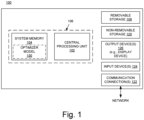
- Figure 1 shows a block diagram of an example of a computer system 100 upon which the embodiments described herein may be implemented.
- the system 100 includes at least one processing unit 102 and memory 104. This most basic configuration is illustrated in Figure 1 by dashed line 106.
- the system 100 may also have additional features and/or functionality.
- the system 100 may also include additional storage (removable and/or non-removable) including, but not limited to, magnetic or optical disks or tape. Such additional storage is illustrated in Figure 1 by removable storage 108 and non-removable storage 120.
- the system 100 may also contain communications connection(s) 122 that allow the device to communicate with other devices, e.g., in a networked environment using logical connections to one or more remote computers.
- the system 100 also includes input device(s) 124 such as keyboard, mouse, pen, voice input device, touch input device, etc.
- Output device(s) 126 such as a display device, speakers, printer, etc., are also included.
- a display device may be, for example, a cathode ray tube display, a light-emitting diode display, or a liquid crystal display.
- the memory 104 includes computer-readable instructions, data structures, program modules, and the like associated with an "optimizer" model 150.
- the optimizer model 150 may instead reside in any one of the computer storage media used by the system 100, or may be distributed over some combination of the computer storage media, or may be distributed over some combination of networked computers. The functionality of the optimizer model 150 is described below.
- FIG 2 is a block diagram illustrating an example of an automated radiation therapy treatment planning system 200 in embodiments according to the present invention.
- the system 200 includes an input interface 210 to receive patient-specific information (data) 201, a data processing component 220 that implements the optimizer model 150, and an output interface 230.
- the system 200 in whole or in part may be implemented as a software program, hardware logic, or a combination thereof on/using the computer system 100 ( Figure 1 ).
- the patient-specific information is provided to and processed by the optimizer model 150.
- the optimizer model 150 yields a prediction result.
- a treatment plan based on the prediction result can then be generated.
- Figure 3 illustrates a knowledge-based planning system 300 in embodiments according to the present invention.
- the system 300 includes a knowledge base 302 and a treatment planning tool set 310.
- the knowledge base 302 includes patient records 304 (e.g., radiation treatment plans), treatment types 306, and statistical models 308.
- the treatment planning tool set 310 in the example of Figure 3 includes a current patient record 312, a treatment type 314, a medical image processing module 316, the optimizer model (module) 150, a dose distribution module 320, and a final radiation treatment plan 322.
- the treatment planning tool set 310 searches through the knowledge base 302 (through the patient records 304) for prior patient records that are similar to the current patient record 312.
- the statistical models 308 can be used to compare the predicted results for the current patient record 312 to a statistical patient.
- a selected treatment type 306, and selected statistical models 308, the tool set 310 uses the current patient record 312, a selected treatment type 306, and selected statistical models 308, the tool set 310 generates a radiation treatment plan 322.
- a first-step treatment type 314 can be chosen.
- Patient outcomes which can include normal tissue complication probability as a function of dose rate and patient-specific treatment-type outcomes (e.g., local recurrent failure, and overall survival as a function of a dose rate-volume histogram ( Figure 7A ) and/or an irradiation time-volume histogram ( Figure 7D )), can be included in the treatment planning process.
- the medical image processing module 316 provides automatic contouring and automatic segmentation of two-dimensional cross-sectional slides (e.g., from any imaging modality such as, but not limited to, computed tomography (CT), positron emission tomography-CT, magnetic resonance imaging, and ultrasound) to form a three-dimensional (3D) image using the medical images in the current patient record 312.
- CT computed tomography
- positron emission tomography-CT magnetic resonance imaging
- ultrasound ultrasound
- Dose distribution maps and dose rate distribution maps are calculated by the dose and dose rate distribution module 320, which may utilize the optimizer model 150.
- the optimizer model 150 uses a dose prediction model to provide, for example, a 3D dose distribution, fluences, and dose rates, and associated dose-volume histograms and dose rate-volume histograms.
- Figure 4 is a block diagram showing selected components of a radiation therapy system 400 upon which embodiments according to the present invention can be implemented.
- the system 400 includes a beam system 404 and a nozzle 406.
- the beam system 404 generates and transports a beam 401.
- the beam 401 can be a proton beam, electron beam, photon beam, ion beam, or atom nuclei beam (e.g., carbon, helium, and lithium).
- the beam system 404 includes components that direct (e.g., bend, steer, or guide) the beam system in a direction toward and into a nozzle 406.
- the radiation therapy system may include one or more multileaf collimators (MLCs); each MLC leaf can be independently moved back-and-forth by the control system 410 to dynamically shape an aperture through which the beam can pass, to block or not block portions of the beam and thereby control beam shape and exposure time.
- the beam system 404 may also include components that are used to adjust (e.g., reduce) the beam energy entering the nozzle 406.
- the nozzle 406 is used to aim the beam toward various locations (a target volume) within an object (e.g., a patient) supported on the patient support device 408 (e.g., a chair or table) in a treatment room.
- a target volume may be an organ, a portion of an organ (e.g., a volume or region within the organ), a tumor, diseased tissue, or a patient outline.
- a target volume may include both unhealthy tissue (e.g., a tumor) and healthy tissue.
- the nozzle 406 may be mounted on or a part of a gantry that can be moved relative to the patient support device 408, which may also be moveable.
- the beam system 404 is also mounted on or is a part of the gantry.
- the beam system is separate from (but in communication with) the gantry.
- the control system 410 of Figure 4 receives and implements a prescribed radiation treatment plan.
- the control system 410 includes a computer system having a processor, memory, an input device (e.g., a keyboard), and perhaps a display in well-known fashion.
- the control system 410 can receive data regarding operation of the system 400.
- the control system 410 can control parameters of the beam system 404, nozzle 406, and patient support device 408, including parameters such as the energy, intensity, direction, size, and/or shape of the beam, according to data it receives and according to the prescribed radiation treatment plan.
- the nozzle 406 includes one or more components that affect (e.g., decrease, modulate) the energy of the beam.
- the term "beam energy adjuster” is used herein as a general term for a component or components that affect the energy of the beam, in order to control the range of the beam (e.g., the extent that the beam penetrates into a target), to control the dose delivered by the beam, and/or to control the depth dose curve of the beam, depending on the type of beam.
- the beam energy adjuster can control the location of the Bragg peak in the target volume.
- the beam energy adjuster 407 includes a range modulator, a range shifter, or both a range modulator and a range shifter.
- intensity modulated radiation therapy IMRT
- intensity modulated particle therapy IMPT
- beam intensity is varied across each treatment region (target volume) in a patient.
- degrees of freedom available for intensity modulation include beam shaping (collimation), beam weighting (spot scanning), and angle of incidence (which may be referred to as beam geometry).
- Figure 5 illustrates a beam's eye view (BEV) of a beam 502 in embodiments according to the invention. That is, Figure 5 illustrates a cross-section of a beam.
- the beam 502 is illustrated as being rectangular in shape having a height H and width W.
- the invention is not so limited, and the beam 502 can have virtually any regular or irregular cross-sectional (e.g., BEV) shape.
- the shape of the beam 502 can be defined using an MLC that blocks a portion or portions of the beam. Different beams can have different shapes.
- the beam 502 includes a number of beam segments or beamlets (that also may be referred to as spots) exemplified by beam segments 504, 506, and 508.
- a maximum energy e.g. 80 MeV
- an energy level is defined for each of the beam segments as a percentage or fraction of the maximum energy.
- each of the beam segments is weighted in terms of its energy level; some beam segments are weighted to have a higher energy level than other beam segments.
- the defined energy level or intensity can be realized for each beam segment using the beam energy adjuster 407 of Figure 4 .
- Each beam segment can deliver a relatively high dose rate (a relatively high dose in a relatively short period of time).
- each beam segment can deliver at least four grays (Gy) in less than one second, and may deliver as much as 20 Gy to 50 Gy or 100 Gy or more in less than one second.
- the beam segments are delivered sequentially.
- the beam segment 504 is delivered to the target volume (turned on) and then turned off, then the beam segment 506 is turned on then off, then the beam segment 508 is turned on then off, and so on.
- Each beam segment may be turned on for only a fraction of a second (e.g., on the order of milliseconds).
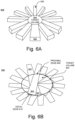
- Figure 6A illustrates a perspective view of an example of a beam geometry in embodiments according to the invention.
- the beams (exemplified by beam 602) are in the same plane.
- the beams can be proton beams, electron beams, photon beams, ion beams, or atom nuclei beams.
- Each beam can deliver a relatively high dose rate (a relatively high dose in a relatively short period of time).
- each beam can deliver doses sufficient for FLASH RT (e.g., at least 4 Gy in less than one second, and as much as 20 Gy to 50 Gy or 100 Gy or more in less than one second).
- Each beam can include one or more beam segments or beamlets.
- the beams' paths overlap only within the target volume 604, and do not overlap outside the target volume in the surrounding tissue 606.
- the beam 602 (for example) is illustrated as passing completely through the target volume 604.
- the ranges of the beams can be controlled so that the beam does not pass completely through the target volume.
- Figure 6B illustrates a cross-sectional view of an example of a beam geometry in embodiments according to the invention.
- the beams (exemplified by beams 605 and 607) overlap only within the target volume and are in the same plane.
- the figure depicts the beams in overlapping fashion to demonstrate that each portion of the target volume 604 receives a dose of radiation.
- the beams can be proton beams, electron beams, photon beams, ion beams, or atom nuclei beams.
- the beams are illustrated as not extending beyond the distal edge of the target volume 604 (as would be the case for proton or ion beams, for example); however, the invention is not so limited.
- Each beam can deliver a relatively high dose in a relatively short period of time. For example, each beam can deliver dose rates sufficient for FLASH RT.
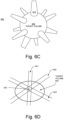
- Figure 6C illustrates a perspective view of an example of a beam geometry in embodiments according to the invention.
- the beams (exemplified by beam 612) are in different planes.
- Each beam can include one or more beam segments or beamlets.
- the beams' paths overlap only within the target volume 604, and do not overlap outside the target volume in the surrounding tissue 606.
- the beams can be proton beams, electron beams, photon beams, ion beams, or atom nuclei beams.
- Each beam can deliver a relatively high dose in a relatively short period of time. For example, each beam can deliver dose rates sufficient for FLASH RT.
- Figure 6D illustrates a cross-sectional view of an example of a beam geometry in embodiments according to the invention.
- the beams (exemplified by beams 621, 622, and 623) overlap only within the target volume and are in the same plane. While three beams are illustrated, the invention is not so limited.
- each beam can include one or more beam segments or beamlets.
- the beams' paths overlap only within the target volume 604, and do not overlap outside the target in the surrounding tissue 606. Although multiple beams are shown in the figure, all beams are not necessarily delivered at the same time or in overlapping time periods as mentioned above.
- the beams can be proton beams, electron beams, photon beams, ion beams, or atom nuclei beams.
- Each beam can deliver a relatively high dose in a relatively short period of time. For example, each beam can deliver dose rates sufficient for FLASH RT.
- the beams 621, 622, and 623 intersect at the sub-volume 630, other sub-volumes in the target volume 604 receive doses from two of the beams, other sub-volumes in the target volume receive doses from only one of the beams, and yet other sub-volumes do not receive a dose.
- the directions and/or numbers of beam can be varied over a number of treatment sessions (that is, fractionated in time) so that a uniform dose is delivered across the target.
- a dose rate-volume histogram (which is different from, but may be used with, a dose-volume histogram) is generated for a target volume.
- the dose rate-volume histogram is generated based on a proposed radiation treatment plan.
- the dose rate-volume histogram is stored in computer system memory and used to generate a final radiation treatment plan that will be used to treat a patient. Values of parameters that can have an effect on dose rate are adjusted until the dose rate-volume histogram satisfies objectives of or associated with treatment of the patient.
- FIG 7A illustrates an example of a dose rate-volume histogram 700 in an embodiment according to the present invention.
- the dose rate-volume histogram plots a cumulative dose rate-to-target volume frequency distribution that summarizes the simulated dose rate distribution within a target volume of interest (e.g., the target volume 604 of Figures 6A-6D ) that would result from a proposed radiation treatment plan.
- the simulated dose rate distribution can be determined using the optimizer model 150 of Figure 1 .
- the dose rate-volume histogram indicates dose rates and percentages of the target volume that receive the dose rates. For example, as shown in Figure 7A , 100 percent of the target volume receives a dose rate of X, 50 percent of the target volume receives a dose rate of Y, and so on.
- the dose rate-volume histogram 700 can be displayed as or as part of a graphical user interface (GUI) (see the discussion of Figures 11 , 12, and 13 , below).
- GUI graphical user interface
- the target volume 604 may include different organs, for example, or it may include both healthy tissue and unhealthy tissue (e.g., a tumor). Accordingly, with reference to Figures 7B and 7C , the dose rate-volume histogram 710 includes multiple curves 712 and 714, showing the simulated dose rate distribution for a first sub-volume 722 of the target volume (e.g., for one organ, or for the healthy tissue) and the simulated dose rate distribution for a second sub-volume 724 (e.g., for a second organ, or for the unhealthy tissue), respectively. More than two simulated dose rate distributions can be included in a dose rate-volume histogram.
- the dose rate-volume histogram 710 can be displayed as or as part of a GUI (see the discussion of Figures 11 , 12, and 13 , below).
- the target volume 604 may be divided (virtually) into a number of voxels.
- a sub-volume can include a single voxel or multiple voxels.
- an irradiation time-volume histogram (which is different from, but may be used with, a dose-volume histogram and/or a dose rate-volume histogram) is generated for the target volume.
- the irradiation time-volume histogram can be stored in computer system memory and used to generate a radiation treatment plan, in combination with or in lieu of a dose-volume histogram and/or a dose rate-volume histogram.
- Figure 7D illustrates an example of an irradiation time-volume histogram 750 in an embodiment according to the present invention.
- the irradiation time-volume histogram plots a cumulative irradiation time-to-target volume frequency distribution that summarizes the simulated irradiation time distribution within a target volume of interest (e.g., the target volume 604 of Figures 6A-6D ) that would result from a proposed radiation treatment plan.
- the simulated irradiation time distribution can be determined using the optimizer model 150 of Figure 1 .
- the irradiation time-volume histogram indicates irradiation times (lengths of times) and percentages of the target volume that are irradiated for those lengths of time.
- the dose rate-volume histogram 750 can be displayed as or as part of a GUI (see the discussion of Figures 11 , 12, and 13 , below).
- Figure 8 is a flowchart 800 of an example of computer-implemented operations for radiation treatment planning including generating a dose rate-volume histogram or an irradiation time-volume histogram in embodiments according to the present invention.
- the flowchart 800 can be implemented as computer-executable instructions (e.g., the optimizer model 150 of Figure 1 ) residing on some form of computer-readable storage medium (e.g., in memory of the computer system 100 of Figure 1 ).
- a proposed radiation treatment plan is defined (e.g., using the optimizer model 150 of Figures 1 and 2 ), stored in a computer system memory, and accessed.
- the proposed radiation treatment plan includes values of parameters that can affect dose rate, as well as other parameters.
- the parameters that can affect dose rate include, but are not limited to, a number of irradiations of the target volume, a duration of each of the irradiations (irradiation times), and a dose deposited in each of the irradiations.
- the parameters may also include directions of beams to be directed into the target volume, and beam energies for each of the beams.
- the parameters may also include a period of time during which the irradiations are applied (e.g., a number of irradiations are applied over a period of time such as an hour, with each irradiation in the period of time separated from the next by another period of time) and an interval of time between each period of irradiations (e.g., each hour-long period is separated from the next by a day).
- a period of time during which the irradiations are applied e.g., a number of irradiations are applied over a period of time such as an hour, with each irradiation in the period of time separated from the next by another period of time
- an interval of time between each period of irradiations e.g., each hour-long period is separated from the next by a day.
- Appropriate dose threshold curve(s) can be utilized in the optimization model 150 ( Figure 3 ) to establish dose limits for radiation treatment planning.
- the appropriate (e.g., tissue-dependent) dose threshold curve can be used to determine beam directions (gantry angles) and beam segment weights ( Figure 7A ). That is, parameters that affect dose can be adjusted during radiation treatment planning so that the limits in the dose threshold curve are satisfied.
- the dose threshold curves can be tissue-dependent. For instance, the dose threshold curve for the lungs may be different from that for the brain.
- Dose limits can include, but are not limited to: a maximum limit on irradiation time for each sub-volume (voxel) in the target (e.g., for each voxel of target tissue, treatment time less than x1 seconds); a maximum limit on irradiation time for each sub-volume (voxel) outside the target (e.g., for each voxel of normal tissue, treatment time less than x2 seconds; x1 and x2 may be the same or different); a minimum limit on dose rate for each sub-volume (voxel) in the target (e.g., for each voxel of target tissue, dose rate greater than y1 Gy/sec); and a minimum limit on dose rate for each sub-volume (voxel) outside the target (e.g., f or each voxel of normal tissue, dose rate greater than y2 Gy/sec; y1 and y2 may be the same or different).
- the limits are intended to minimize the amount
- a dose rate-volume histogram is generated based on the values of the parameters in the proposed radiation treatment plan.
- a dose rate can be determined per sub-volume or voxel.
- the dose rate is the dose deposited in each irradiation divided by the sum of the durations of the irradiation, times the number of irradiations (e.g., number of fractions).
- the dose rate can be determined and recorded using a fine time index (e.g., time increments on the order of a millisecond); that is, for example, the dose to each sub-volume or voxel can be recorded for time increments on the order of per-millisecond per beam and per fraction.
- the dose rate is cumulative.
- the cumulative dose rate for some portions (e.g., sub-volumes or voxels) of the target volume may be higher than other portions, depending on the beam directions and energies, for example.
- the dose rate per sub-volume or voxel can be calculated to include ray tracing (and Monte Carlo-like simulations), where each beam particle is tracked to determine the primary, secondary, etc., scatters for each particle to get a realistic voxel-based or sub-volume-based dose rate over the course of each irradiation.
- an irradiation time-volume histogram is generated.
- An irradiation time-volume histogram can be generated essentially in the same manner as that just described for generating a dose rate-volume histogram. Both a dose rate-volume histogram and an irradiation time-volume histogram, or only a dose rate-volume histogram, or only an irradiation time-volume histogram, can be generated, in addition to or in lieu of a dose-volume histogram.
- the dose rate-volume histogram and/or the irradiation time-volume histogram can be evaluated by determining whether or not objectives (e.g., clinical goals) that are specified for treatment of a patient are satisfied by the proposed radiation treatment plan.
- the clinical goals or objectives may be expressed in terms of a set of quality metrics, such as target homogeneity, critical organ sparing, and the like, with respective target values for the metrics.
- Another way to evaluate the dose rate-volume histogram and/or the irradiation time-volume histogram is a knowledge-based approach that incorporates and reflects present best practices gathered from multiple previous, similar treatments of other patients.
- Yet another way to assist the planner is to use a multi-criteria optimization (MCO) approach for treatment planning.
- MCO multi-criteria optimization
- Pareto surface navigation is an MCO technique that facilitates exploration of the tradeoffs between clinical goals. For a given set of clinical goals, a treatment plan is considered to be Pareto optimal if it satisfies the goals and none of the metrics can be improved without worsening at least one of the other metrics.
- a dose rate-volume histogram can be evaluated by determining whether the percentage of the target volume that receives a dose rate above the dose rate threshold value satisfies the percentage threshold value. For example, a dose-rate volume histogram may be considered to be satisfactory if 80 percent of the target volume (specifically, the portion of the target volume that includes the unhealthy tissue) receives a dose rate of at least 50 Gy per second.
- Another way to evaluate an irradiation time-volume histogram is to define an irradiation time threshold value or values (e.g., a maximum limit on irradiation time for each sub-volume or voxel inside the target volume and/or a maximum limit on irradiation time for each sub-volume or voxel outside the target volume), and to also specify a target volume percentage threshold value or values for irradiation time inside and/or outside the target volume.
- an irradiation time threshold value or values e.g., a maximum limit on irradiation time for each sub-volume or voxel inside the target volume and/or a maximum limit on irradiation time for each sub-volume or voxel outside the target volume
- An irradiation time-volume histogram can be evaluated by determining whether the percentage of the tissue inside the target volume that is irradiated for less than the corresponding irradiation time threshold value satisfies the corresponding percentage threshold value, and/or by similarly determining whether the percentage of the tissue outside the target volume that is irradiated for less than the corresponding irradiation time threshold value satisfies the corresponding percentage threshold value.
- the information in the dose rate-volume histogram is used to determine and represent isolines of dose rate relative to a target volume 904 (e.g., a tumor) that includes or is surrounded by other (e.g., healthy) tissue, as shown in the example of Figure 9 .
- a target volume 904 e.g., a tumor
- other tissue e.g., healthy tissue
- Figure 9 is illustrated in two dimensions, showing either a top down view of the target volume or one cross-sectional slice of the target volume, and can be displayed as or as part of a GUI (see the discussion of Figures 11 , 12, and 13 , below).
- the target volume and isolines can also be represented in three dimensions and displayed as or as part of the GUI.
- Isolines of irradiation time relative to a target volume can be similarly determined and represented.
- some or all of the parameter values for the proposed radiation treatment plan can be iteratively adjusted to generate different dose rate-volume histograms and/or the irradiation time-volume histograms, to determine a final set of parameter values that produce a histogram (or histograms) that results in a prescribed (final) radiation treatment plan that best satisfies the objectives (clinical goals) for treatment of the patient or that satisfies the threshold values described above.
- the final set of parameter values is then included in the prescribed radiation treatment plan used to treat the patient.
- embodiments according to the invention optimize a radiation treatment plan based on dose rate and/or irradiation time. This is not to say that treatment plan optimization is based solely on dose rate and/or irradiation time.
- a dose-volume histogram can be used in conjunction with a dose rate-volume histogram and/or irradiation time-volume histogram when developing a radiation treatment plan.
- Figure 10 is a flowchart 1000 of an example of computer-implemented operations for generating a dose rate-volume histogram in embodiments according to the present invention.
- the flowchart 1000 can be implemented as computer-executable instructions (e.g., the optimizer model 150 of Figure 1 ) residing on some form of computer-readable storage medium (e.g., memory of the computer system 100 of Figure 1 ).
- the information in computer system memory is accessed.
- the information includes a dose rate received by a target volume per sub-volume or voxel, determined using a dose prediction model implemented with the optimizer model 150 ( Figure 1 ).
- the information also can include irradiation time (duration) per sub-volume or voxel.
- a dose rate-volume histogram and/or an irradiation time-volume histogram are/is generated for the target volume, as previously described herein (e.g., with reference to Figure 8 ).
- histograms that are generated are stored in computer system memory.
- the dose rate-volume histogram and/or the irradiation time-volume histogram are/is used to generate a radiation treatment plan for treating the target volume.
- FIG 11 illustrates an example of a GUI 1100 that can be used to display information associated with a radiation treatment plan in embodiments according to the present invention.
- the GUI 1100 can be implemented using computer-executable instructions (e.g., the optimizer model 150 of Figure 1 ) residing on some form of computer-readable storage medium (e.g., memory of the computer system 100 of Figure 1 ), and can be displayed on the output device 126 of the computer system.
- computer-executable instructions e.g., the optimizer model 150 of Figure 1
- some form of computer-readable storage medium e.g., memory of the computer system 100 of Figure 1
- the GUI includes four windows 1104, 1105, 1106, and 1107, but the invention is not so limited.
- the window 1104 includes a menu or listing of different proposed radiation treatment plans (e.g., plan 1 and plan 2). If, for example, plan 2 is selected, then information associated with that plan is displayed in the windows 1106 and 1107.
- the window 1105 includes a menu or listing of types of information that can be presented in the GUI 1100.
- the types of information may include, but are not limited to, dose, dose rate, and irradiation time.
- the window 1106 displays a representation of a target volume 1108.
- the representation can be two-dimensional, representing a cross-sectional slice of the target volume 1108, or it can be a virtual three-dimensional representation of the target volume.
- the target volume 1108 includes four sub-volumes 1110, 1111, 1112, and 1113 (1110-1113).
- the sub-volumes 1110-1113 may represent different regions (e.g., healthy tissue and non-healthy tissue or tumor) within a patient, different organs within a patient, or different regions within tissue or an organ, for example.
- the sub-volumes 1110-1113 can be any shape.
- a sub-volume may be a single voxel or a set of voxels within a region or organ.
- a value of an attribute is associated with each of the sub-volumes 1110-1113.
- the attribute can be, but is not limited to, color, pattern, gray-scale, alphanumeric text, and brightness, or a combination of one or more of these.
- the value can be, for example, a particular color, a particular pattern, a level of gray-scale, a character or combination of characters, or a level of brightness.
- the value of the attribute for a sub-volume corresponds to, for example, the amount of the dose rate, the amount of dose, or the irradiation time received by or associated with the sub-volume according to the selected radiation plan (e.g., plan 2).
- one color value e.g., blue
- a second color value e.g., green
- a dose rate between the first threshold and a second threshold and so on.
- the dose rate received by a sub-volume can be determined using parameters including the number of irradiations of the sub-volume, a duration of each of the irradiations, a dose deposited in each of the irradiations, the dose rate accumulated over the number of irradiations of the sub-volume, and the dose rate accumulated over the number of irradiations of the sub-volume divided by the number of irradiations of the sub-volume.
- This type of information can also be presented in the GUI 1100.
- the value of the attribute for a sub-volume can correspond to one of the parameters.
- a first color value may correspond to a first number of irradiations
- a second color value may correspond to a second number of irradiations, and so on.
- the GUI 1100 can also be used to present information such as the directions of beams to be directed into each sub-volume, and beam energies for each of the beams.
- the window 1107 displays a selected histogram or a selected set of isolines.
- the window 1107 can include a dose rate-volume histogram (e.g., the histograms 700 and 710 of Figures 7A and 7B ).
- a dose rate-volume histogram e.g., the histograms 700 and 710 of Figures 7A and 7B .
- an irradiation time-volume histogram e.g., the histogram 750 of Figure 7D
- dose rate isolines e.g., Figure 9
- irradiation time isolines can be displayed.
- drop-down menus or other types of GUI elements can be used to select and establish settings (e.g., attributes, thresholds, etc.) for the GUI 1100 and the type(s) of information to be displayed at any one time.
- settings e.g., attributes, thresholds, etc.
- the GUI 1100 is not necessarily a static display.
- the information presented in the GUI 1100 can be programmed to change over time to illustrate accumulated dose or dose rate versus time.
- the GUI 1100 can be programmed to present different cross-sectional slices of the target volume 1108 in sequence to provide a depth dimension to the two-dimensional representation, or to manipulate (e.g., rotate) the virtual three-dimensional representation so that it can be viewed from different perspectives.
- Figures 12 and 13 are flowcharts 1200 and 1300, respectively, of examples of computer-implemented operations for generating a GUI (e.g., the GUI 1100 of Figure 11 ) in embodiments according to the present invention.
- the flowcharts 1200 and 1300 can be implemented as computer-executable instructions (e.g., the optimizer model 150 of Figure 1 ) residing on some form of computer-readable storage medium (e.g., in memory of the computer system 100 of Figure 1 ).
- information in the computer system memory is accessed.
- the information includes a dose rate received by each sub-volume of a target volume.
- the dose rate received by each sub-volume is determined as previously described herein.
- the information includes an irradiation time per sub-volume.
- a value of an attribute is associated with each sub-volume.
- the value corresponds to an amount of the dose rate received by a respective sub-volume.
- the attribute can be, for example, color, pattern, gray-scale, alphanumeric text, brightness, or a combination of these attributes.
- the value can be, for example, a particular color, a particular pattern, a level of gray-scale, a character or combination of characters, or a level of brightness.
- each sub-volume is rendered and displayed according to the value that corresponds to the sub-volume as described above.
- information that includes a dose rate received by a target volume is accessed from the memory of the computer system.
- a histogram is generated for the target volume.
- the histogram may be a dose rate-volume histogram and/or an irradiation time-volume histogram as previously described herein.
- the histogram is displayed in a GUI as described above.
- embodiments according to the invention improve radiation treatment planning and the treatment itself by expanding FLASH RT to a wider variety of treatment platforms and target sites.
- Treatment plans generated as described herein are superior for sparing normal tissue from radiation in comparison to conventional techniques even for non-FLASH dose rates by reducing, if not minimizing, the magnitude (and the integral in some cases) of the dose to normal tissue (outside the target) by design.
- management of patient motion is simplified because the doses are applied in a short period of time (e.g., less than a second).
- Treatment planning while still a complex task of finding a balance between competing and related parameters, is simplified relative to conventional planning.
- the techniques described herein may be useful for stereotactic radiosurgery as well as stereotactic body radiotherapy with single or multiple metastases.
- a GUI facilitates treatment planning by allowing a planner to readily visualize key elements of a proposed treatment plan (e.g., the dose rate per sub-volume), to readily visualize the effects on those elements of changes to the proposed plan, and to readily visualize a comparison between different plans.
- key elements of a proposed treatment plan e.g., the dose rate per sub-volume
- embodiments according to the invention can be used in spatially fractionated radiation therapy including high-dose spatially fractionated grid radiation therapy and microbeam radiation therapy.
Landscapes
- Health & Medical Sciences (AREA)
- Engineering & Computer Science (AREA)
- Medical Informatics (AREA)
- General Health & Medical Sciences (AREA)
- Public Health (AREA)
- Primary Health Care (AREA)
- Epidemiology (AREA)
- Biomedical Technology (AREA)
- Pathology (AREA)
- Animal Behavior & Ethology (AREA)
- Veterinary Medicine (AREA)
- Life Sciences & Earth Sciences (AREA)
- Radiology & Medical Imaging (AREA)
- Nuclear Medicine, Radiotherapy & Molecular Imaging (AREA)
- Radiation-Therapy Devices (AREA)
Claims (14)
- Système de planification de radiothérapie comprenant :un processeur ;un dispositif d'affichage couplé au processeur ; etune mémoire couplée au processeur et comprenant des instructions qui, lorsqu'elles sont exécutées, amènent le processeur à exécuter un procédé, le procédé comprenant :la génération d'un histogramme de volume de débit de dose pour un volume cible, l'histogramme de volume de débit de dose indiquant des débits de dose et des pourcentages du volume cible qui reçoivent les débits de dose, l'histogramme de volume de débit de dose étant généré sur la base de valeurs de paramètres dans un plan de traitement proposé ;l'affichage d'une interface utilisateur graphique (GUI) comprenant un rendu d'un volume cible, le volume cible comprenant une pluralité de sous-volumes ; etl'accès à des informations dans la mémoire, les informations comprenant un débit de dose reçu par chaque sous-volume des sous-volumes, le débit de dose étant reçu par un sous-volume déterminé à l'aide desdits paramètres ;dans lequel ledit affichage comprend :l'association d'une valeur d'un attribut audit chaque sous-volume, dans lequel ladite valeur correspond à une quantité du débit de dose reçu par ledit chaque sous-volume ;le rendu dudit chaque sous-volume en fonction de la valeur qui correspond audit chaque sous-volume ; etl'affichage de l'histogramme de volume de débit de dose dans le cadre la GUI ;dans lequel le procédé exécuté par le processeur comprend en outre le réglage de valeurs de paramètres qui peuvent avoir un effet sur le débit de dose jusqu'à ce que l'histogramme de volume de débit de dose satisfasse des objectifs associés au traitement d'un patient et la génération d'un plan de radiothérapie final à l'aide de l'histogramme de volume de débit de dose.
- Système de planification de radiothérapie selon la revendication 1, dans lequel le débit de dose reçu par ledit chaque sous-volume est déterminé à l'aide de paramètres comprenant un nombre d'irradiations dudit chaque sous-volume, une durée de chacune des irradiations, et une dose déposée dans chacune des irradiations.
- Système de planification de radiothérapie selon la revendication 1 ou la revendication 2, dans lequel la quantité du débit de dose reçue par ledit chaque sous-volume est une quantité choisie dans le groupe constitué : du débit de dose accumulé sur le nombre d'irradiations dudit chaque sous-volume ; et du débit de dose accumulé sur le nombre d'irradiations dudit chaque sous-volume divisé par le nombre d'irradiations dudit chaque sous-volume.
- Système de planification de radiothérapie selon une quelconque revendication précédente, dans lequel les paramètres comprennent en outre : une période de temps pendant laquelle les irradiations sont appliquées, et un intervalle de temps entre chaque période d'irradiations.
- Système de planification de radiothérapie selon une quelconque revendication précédente, dans lequel les paramètres comprennent en outre : des directions de faisceaux à diriger dans ladite chaque sous-volume, et des énergies de faisceau pour chacun des faisceaux.
- Système de planification de radiothérapie selon la revendication 5, dans lequel les faisceaux comprennent un type de faisceau choisi dans le groupe constitué : d'un proton ; d'un électron ; d'un photon ; de noyaux d'atome ; et d'un ion.
- Système de planification de radiothérapie selon une quelconque revendication précédente, dans lequel l'attribut est choisi dans le groupe constitué : d'une couleur ; d'un motif ; d'une échelle de gris ; d'un texte alphanumérique ; et d'une luminosité.
- Système de planification de radiothérapie selon une quelconque revendication précédente, dans lequel le rendu du volume cible est choisi dans le groupe constitué : d'une section transversale bidimensionnelle du volume cible ; et d'une représentation tridimensionnelle virtuelle du volume cible.
- Système de planification de radiothérapie selon une quelconque revendication précédente, dans lequel la GUI comprend en outre des isolignes de débits de dose par rapport au volume cible sur la base de l'histogramme de volume de débit de dose.
- Système de planification de radiothérapie selon une quelconque revendication précédente, dans lequel la GUI comprend en outre un histogramme de volume de temps d'irradiation pour le volume cible, dans lequel l'histogramme de volume de temps d'irradiation indique un pourcentage du volume cible qui est irradié pendant une durée respective.
- Support de stockage non transitoire lisible par ordinateur ayant des instructions exécutables par ordinateur pour amener un système informatique à exécuter une planification de radiothérapie, le procédé comprenant :la génération d'un histogramme de volume de débit de dose pour un volume cible, l'histogramme de volume de débit de dose indiquant des débits de dose et des pourcentages du volume cible qui reçoivent les débits de dose, l'histogramme de volume de débit de dose étant généré sur la base de valeurs de paramètres dans un plan de traitement proposé ;la détermination, sur la base du plan de radiothérapie, d'un débit de dose reçu par chaque sous-volume d'une pluralité de sous-volumes d'un volume cible, le débit de dose reçu par un sous-volume étant déterminé à l'aide desdits paramètres ; etl'affichage d'une interface utilisateur graphique (GUI) comprenant un rendu du volume cible ; ledit affichage comprenant :l'association d'une valeur d'un attribut audit chaque sous-volume, dans lequel ladite valeur correspond à une quantité du débit de dose reçu par ledit chaque sous-volume ;le rendu dudit chaque sous-volume en fonction de la valeur qui correspond audit chaque sous-volume ; etl'affichage de l'histogramme de volume de débit de dose dans le cadre la GUI ;dans lequel le procédé exécuté par le système informatique comprend en outre le réglage de valeurs de paramètres qui peuvent avoir un effet sur le débit de dose jusqu'à ce que l'histogramme de volume de débit de dose satisfasse des objectifs associés au traitement d'un patient et la génération d'un plan de radiothérapie final à l'aide de l'histogramme de volume de débit de dose.
- Support de stockage non transitoire lisible par ordinateur selon la revendication 11, dans lequel le débit de dose reçu par ledit chaque sous-volume est déterminé à l'aide de paramètres comprenant un nombre d'irradiations dudit chaque sous-volume, une durée de chacune des irradiations, et une dose déposée dans chacune des irradiations.
- Support de stockage non transitoire lisible par ordinateur selon la revendication 11 ou la revendication 12, dans lequel la GUI comprend en outre des isolignes de débits de dose par rapport au volume cible sur la base de l'histogramme de volume de débit de dose.
- Support de stockage non transitoire lisible par ordinateur selon l'une quelconque de la revendication 11 à la revendication 13, dans lequel la GUI comprend en outre un histogramme de volume de temps d'irradiation pour le volume cible, dans lequel l'histogramme de volume de temps d'irradiation indique un pourcentage du volume cible qui est irradié pendant une durée respective.
Applications Claiming Priority (2)
| Application Number | Priority Date | Filing Date | Title |
|---|---|---|---|
| US16/294,702 US20200286601A1 (en) | 2019-03-06 | 2019-03-06 | Graphical display of dose rate information for radiation treatment planning |
| PCT/US2020/021091 WO2020181036A2 (fr) | 2019-03-06 | 2020-03-05 | Affichage graphique d'informations de débit de dose pour planification de radiothérapie |
Publications (2)
| Publication Number | Publication Date |
|---|---|
| EP3934748A2 EP3934748A2 (fr) | 2022-01-12 |
| EP3934748B1 true EP3934748B1 (fr) | 2024-08-21 |
Family
ID=70005833
Family Applications (1)
| Application Number | Title | Priority Date | Filing Date |
|---|---|---|---|
| EP20714452.8A Active EP3934748B1 (fr) | 2019-03-06 | 2020-03-05 | Affichage graphique d'informations de débit de dose pour planification de radiothérapie |
Country Status (4)
| Country | Link |
|---|---|
| US (1) | US20200286601A1 (fr) |
| EP (1) | EP3934748B1 (fr) |
| CN (1) | CN113557057A (fr) |
| WO (1) | WO2020181036A2 (fr) |
Families Citing this family (15)
| Publication number | Priority date | Publication date | Assignee | Title |
|---|---|---|---|---|
| JP7311620B2 (ja) | 2019-03-08 | 2023-07-19 | メビオン・メディカル・システムズ・インコーポレーテッド | 粒子線治療システムのためのコリメータおよびエネルギーデグレーダ |
| TWI696190B (zh) * | 2019-03-15 | 2020-06-11 | 國立陽明大學 | 一種透過體積轉換演算法以計算最佳化機頭弧形角度的方法 |
| US10918886B2 (en) * | 2019-06-10 | 2021-02-16 | Varian Medical Systems, Inc. | Flash therapy treatment planning and oncology information system having dose rate prescription and dose rate mapping |
| US11992703B2 (en) | 2020-06-23 | 2024-05-28 | Varian Medical Systems Particle Therapy Gmbh & Co. Kg | Correlation of dose and dose rate information to volume for radiation treatment planning |
| WO2021259977A1 (fr) * | 2020-06-23 | 2021-12-30 | Varian Medical Systems International Ag | Corrélation d'informations de dose et de débit de dose à un volume pour une planification de radiothérapie |
| JP7786970B2 (ja) * | 2021-02-15 | 2025-12-16 | キヤノンメディカルシステムズ株式会社 | 放射線治療計画装置及び放射線治療計画方法 |
| US11590363B2 (en) * | 2021-06-29 | 2023-02-28 | Varian Medical Systems International Ag | Assessing treatment parameters for radiation treatment planning |
| EP4373571A1 (fr) * | 2021-07-20 | 2024-05-29 | Mevion Medical Systems, Inc. | Portique toroïdal pour un système de thérapie par particules |
| JP2023033183A (ja) * | 2021-08-25 | 2023-03-09 | キヤノンメディカルシステムズ株式会社 | 放射線治療計画装置 |
| EP4140538B1 (fr) * | 2021-08-25 | 2025-09-03 | Canon Medical Systems Corporation | Appareil et procédé de planification de radiothérapie |
| US12186592B2 (en) | 2021-12-28 | 2025-01-07 | Varian Medical Systems Particle Therapy Gmbh & Co. Kg | Radiotherapy dose analysis methods and systems |
| US12327013B2 (en) * | 2022-03-30 | 2025-06-10 | Siemens Healthineers International Ag | Graphical user interface control device for radiation therapy treatment planning |
| US12251575B2 (en) * | 2022-06-16 | 2025-03-18 | Siemens Healthineers International Ag | Plan analysis and guidance using voice commands and human language processing |
| US20250082964A1 (en) * | 2023-09-13 | 2025-03-13 | Siemens Healthineers International Ag | Two-step beam geometry optimization and beam entry angles without isocenter |
| US20250372231A1 (en) * | 2024-06-03 | 2025-12-04 | Siemens Healthineers International Ag | Using machine-learning language processing model for radiotherapy visualization |
Citations (3)
| Publication number | Priority date | Publication date | Assignee | Title |
|---|---|---|---|---|
| US20190060667A1 (en) * | 2017-07-21 | 2019-02-28 | Varian Medical Systems, Inc. | Dose aspects of radiation therapy planning and treatment |
| WO2020180994A1 (fr) * | 2019-03-06 | 2020-09-10 | Varian Medical Systems, Inc. | Plan de traitement par rayonnement basé sur un débit de dose |
| WO2021067745A1 (fr) * | 2019-10-03 | 2021-04-08 | Varian Medical Systems, Inc. | Planification de radiothérapie destinée à administrer des niveaux de dose élevés à des points dans une cible |
Family Cites Families (11)
| Publication number | Priority date | Publication date | Assignee | Title |
|---|---|---|---|---|
| US7070554B2 (en) * | 2003-01-15 | 2006-07-04 | Theragenics Corporation | Brachytherapy devices and methods of using them |
| EP1687064A2 (fr) * | 2003-10-07 | 2006-08-09 | Nomos Corporation | Systeme, procede et dispositif pour la planification permettant une radiotherapie conforme |
| US7295649B2 (en) * | 2005-10-13 | 2007-11-13 | Varian Medical Systems Technologies, Inc. | Radiation therapy system and method of using the same |
| US10279196B2 (en) * | 2006-09-28 | 2019-05-07 | Accuray Incorporated | Radiation treatment planning using four-dimensional imaging data |
| US9387344B2 (en) * | 2006-11-21 | 2016-07-12 | The Johns Hopkins University | Methods for determining absorbed dose information |
| US8489431B2 (en) * | 2009-03-20 | 2013-07-16 | General Electric Company | System and method of remote reporting of radiation dose usage in image acquisition |
| WO2012024448A2 (fr) * | 2010-08-17 | 2012-02-23 | Board Of Regents, The University Of Texas System | Planification automatisée du traitement pour la radiothérapie |
| EP3010585B1 (fr) * | 2013-06-18 | 2018-05-09 | Duke University | Systèmes et méthodes permettant de fixer des critères de traitement et des paramètres de traitement pour la planification d'une radiothérapie propre à un patient |
| EP3052188B1 (fr) * | 2013-09-30 | 2021-12-01 | Varian Medical Systems International AG | Prévision de distribution de dose réalisable au moyen d'informations 3d servant d'entrée |
| US9878177B2 (en) * | 2015-01-28 | 2018-01-30 | Elekta Ab (Publ) | Three dimensional localization and tracking for adaptive radiation therapy |
| EP3682945B1 (fr) * | 2019-01-21 | 2021-03-10 | RaySearch Laboratories AB | Procédé et système d'évaluation d'un plan de traitement par radiothérapie |
-
2019
- 2019-03-06 US US16/294,702 patent/US20200286601A1/en active Pending
-
2020
- 2020-03-05 EP EP20714452.8A patent/EP3934748B1/fr active Active
- 2020-03-05 WO PCT/US2020/021091 patent/WO2020181036A2/fr not_active Ceased
- 2020-03-05 CN CN202080019180.1A patent/CN113557057A/zh active Pending
Patent Citations (3)
| Publication number | Priority date | Publication date | Assignee | Title |
|---|---|---|---|---|
| US20190060667A1 (en) * | 2017-07-21 | 2019-02-28 | Varian Medical Systems, Inc. | Dose aspects of radiation therapy planning and treatment |
| WO2020180994A1 (fr) * | 2019-03-06 | 2020-09-10 | Varian Medical Systems, Inc. | Plan de traitement par rayonnement basé sur un débit de dose |
| WO2021067745A1 (fr) * | 2019-10-03 | 2021-04-08 | Varian Medical Systems, Inc. | Planification de radiothérapie destinée à administrer des niveaux de dose élevés à des points dans une cible |
Non-Patent Citations (1)
| Title |
|---|
| P-H MACKEPRANG ET AL: "Assessing dose rate distributions in VMAT plans", PHYSICS IN MEDICINE AND BIOLOGY, INSTITUTE OF PHYSICS PUBLISHING, BRISTOL GB, vol. 61, no. 8, 30 March 2016 (2016-03-30), pages 3208 - 3221, XP020303403, ISSN: 0031-9155, [retrieved on 20160330], DOI: 10.1088/0031-9155/61/8/3208 * |
Also Published As
| Publication number | Publication date |
|---|---|
| WO2020181036A2 (fr) | 2020-09-10 |
| EP3934748A2 (fr) | 2022-01-12 |
| CN113557057A (zh) | 2021-10-26 |
| US20200286601A1 (en) | 2020-09-10 |
Similar Documents
| Publication | Publication Date | Title |
|---|---|---|
| EP3934748B1 (fr) | Affichage graphique d'informations de débit de dose pour planification de radiothérapie | |
| US12161881B2 (en) | Radiation treatment based on dose rate | |
| US12311198B2 (en) | Flash therapy treatment planning and oncology information system having dose rate prescription and dose rate mapping | |
| US11116995B2 (en) | Radiation treatment planning based on dose rate | |
| US11992703B2 (en) | Correlation of dose and dose rate information to volume for radiation treatment planning | |
| EP4363055B1 (fr) | Analyse de la fiabilité d'un débit de dose en fonction d'incertitudes dans la planification d'une radiothérapie | |
| US12599781B2 (en) | Assessing treatment parameters for radiation treatment planning | |
| WO2021259977A1 (fr) | Corrélation d'informations de dose et de débit de dose à un volume pour une planification de radiothérapie | |
| EP3932483B1 (fr) | Procédés et systèmes utilisés pour la planification de traitement par rayonnement |
Legal Events
| Date | Code | Title | Description |
|---|---|---|---|
| STAA | Information on the status of an ep patent application or granted ep patent |
Free format text: STATUS: UNKNOWN |
|
| STAA | Information on the status of an ep patent application or granted ep patent |
Free format text: STATUS: THE INTERNATIONAL PUBLICATION HAS BEEN MADE |
|
| PUAI | Public reference made under article 153(3) epc to a published international application that has entered the european phase |
Free format text: ORIGINAL CODE: 0009012 |
|
| STAA | Information on the status of an ep patent application or granted ep patent |
Free format text: STATUS: REQUEST FOR EXAMINATION WAS MADE |
|
| 17P | Request for examination filed |
Effective date: 20210915 |
|
| AK | Designated contracting states |
Kind code of ref document: A2 Designated state(s): AL AT BE BG CH CY CZ DE DK EE ES FI FR GB GR HR HU IE IS IT LI LT LU LV MC MK MT NL NO PL PT RO RS SE SI SK SM TR |
|
| DAV | Request for validation of the european patent (deleted) | ||
| DAX | Request for extension of the european patent (deleted) | ||
| GRAP | Despatch of communication of intention to grant a patent |
Free format text: ORIGINAL CODE: EPIDOSNIGR1 |
|
| STAA | Information on the status of an ep patent application or granted ep patent |
Free format text: STATUS: GRANT OF PATENT IS INTENDED |
|
| INTG | Intention to grant announced |
Effective date: 20240104 |
|
| GRAJ | Information related to disapproval of communication of intention to grant by the applicant or resumption of examination proceedings by the epo deleted |
Free format text: ORIGINAL CODE: EPIDOSDIGR1 |
|
| STAA | Information on the status of an ep patent application or granted ep patent |
Free format text: STATUS: REQUEST FOR EXAMINATION WAS MADE |
|
| GRAP | Despatch of communication of intention to grant a patent |
Free format text: ORIGINAL CODE: EPIDOSNIGR1 |
|
| STAA | Information on the status of an ep patent application or granted ep patent |
Free format text: STATUS: GRANT OF PATENT IS INTENDED |
|
| INTC | Intention to grant announced (deleted) | ||
| INTG | Intention to grant announced |
Effective date: 20240404 |
|
| GRAS | Grant fee paid |
Free format text: ORIGINAL CODE: EPIDOSNIGR3 |
|
| GRAA | (expected) grant |
Free format text: ORIGINAL CODE: 0009210 |
|
| STAA | Information on the status of an ep patent application or granted ep patent |
Free format text: STATUS: THE PATENT HAS BEEN GRANTED |
|
| AK | Designated contracting states |
Kind code of ref document: B1 Designated state(s): AL AT BE BG CH CY CZ DE DK EE ES FI FR GB GR HR HU IE IS IT LI LT LU LV MC MK MT NL NO PL PT RO RS SE SI SK SM TR |
|
| REG | Reference to a national code |
Ref country code: GB Ref legal event code: FG4D |
|
| REG | Reference to a national code |
Ref country code: CH Ref legal event code: EP |
|
| REG | Reference to a national code |
Ref country code: IE Ref legal event code: FG4D |
|
| REG | Reference to a national code |
Ref country code: DE Ref legal event code: R096 Ref document number: 602020036164 Country of ref document: DE |
|
| REG | Reference to a national code |
Ref country code: LT Ref legal event code: MG9D |
|
| REG | Reference to a national code |
Ref country code: NL Ref legal event code: MP Effective date: 20240821 |
|
| PG25 | Lapsed in a contracting state [announced via postgrant information from national office to epo] |
Ref country code: NO Free format text: LAPSE BECAUSE OF FAILURE TO SUBMIT A TRANSLATION OF THE DESCRIPTION OR TO PAY THE FEE WITHIN THE PRESCRIBED TIME-LIMIT Effective date: 20241121 |
|
| REG | Reference to a national code |
Ref country code: AT Ref legal event code: MK05 Ref document number: 1714962 Country of ref document: AT Kind code of ref document: T Effective date: 20240821 |
|
| PG25 | Lapsed in a contracting state [announced via postgrant information from national office to epo] |
Ref country code: FI Free format text: LAPSE BECAUSE OF FAILURE TO SUBMIT A TRANSLATION OF THE DESCRIPTION OR TO PAY THE FEE WITHIN THE PRESCRIBED TIME-LIMIT Effective date: 20240821 Ref country code: NL Free format text: LAPSE BECAUSE OF FAILURE TO SUBMIT A TRANSLATION OF THE DESCRIPTION OR TO PAY THE FEE WITHIN THE PRESCRIBED TIME-LIMIT Effective date: 20240821 Ref country code: PT Free format text: LAPSE BECAUSE OF FAILURE TO SUBMIT A TRANSLATION OF THE DESCRIPTION OR TO PAY THE FEE WITHIN THE PRESCRIBED TIME-LIMIT Effective date: 20241223 Ref country code: GR Free format text: LAPSE BECAUSE OF FAILURE TO SUBMIT A TRANSLATION OF THE DESCRIPTION OR TO PAY THE FEE WITHIN THE PRESCRIBED TIME-LIMIT Effective date: 20241122 Ref country code: PL Free format text: LAPSE BECAUSE OF FAILURE TO SUBMIT A TRANSLATION OF THE DESCRIPTION OR TO PAY THE FEE WITHIN THE PRESCRIBED TIME-LIMIT Effective date: 20240821 |
|
| PG25 | Lapsed in a contracting state [announced via postgrant information from national office to epo] |
Ref country code: BG Free format text: LAPSE BECAUSE OF FAILURE TO SUBMIT A TRANSLATION OF THE DESCRIPTION OR TO PAY THE FEE WITHIN THE PRESCRIBED TIME-LIMIT Effective date: 20240821 |
|
| PG25 | Lapsed in a contracting state [announced via postgrant information from national office to epo] |
Ref country code: LV Free format text: LAPSE BECAUSE OF FAILURE TO SUBMIT A TRANSLATION OF THE DESCRIPTION OR TO PAY THE FEE WITHIN THE PRESCRIBED TIME-LIMIT Effective date: 20240821 |
|
| PG25 | Lapsed in a contracting state [announced via postgrant information from national office to epo] |
Ref country code: AT Free format text: LAPSE BECAUSE OF FAILURE TO SUBMIT A TRANSLATION OF THE DESCRIPTION OR TO PAY THE FEE WITHIN THE PRESCRIBED TIME-LIMIT Effective date: 20240821 Ref country code: IS Free format text: LAPSE BECAUSE OF FAILURE TO SUBMIT A TRANSLATION OF THE DESCRIPTION OR TO PAY THE FEE WITHIN THE PRESCRIBED TIME-LIMIT Effective date: 20241221 |
|
| PG25 | Lapsed in a contracting state [announced via postgrant information from national office to epo] |
Ref country code: HR Free format text: LAPSE BECAUSE OF FAILURE TO SUBMIT A TRANSLATION OF THE DESCRIPTION OR TO PAY THE FEE WITHIN THE PRESCRIBED TIME-LIMIT Effective date: 20240821 |
|
| PG25 | Lapsed in a contracting state [announced via postgrant information from national office to epo] |
Ref country code: RS Free format text: LAPSE BECAUSE OF FAILURE TO SUBMIT A TRANSLATION OF THE DESCRIPTION OR TO PAY THE FEE WITHIN THE PRESCRIBED TIME-LIMIT Effective date: 20241121 Ref country code: ES Free format text: LAPSE BECAUSE OF FAILURE TO SUBMIT A TRANSLATION OF THE DESCRIPTION OR TO PAY THE FEE WITHIN THE PRESCRIBED TIME-LIMIT Effective date: 20240821 |
|
| PG25 | Lapsed in a contracting state [announced via postgrant information from national office to epo] |
Ref country code: RS Free format text: LAPSE BECAUSE OF FAILURE TO SUBMIT A TRANSLATION OF THE DESCRIPTION OR TO PAY THE FEE WITHIN THE PRESCRIBED TIME-LIMIT Effective date: 20241121 Ref country code: PT Free format text: LAPSE BECAUSE OF FAILURE TO SUBMIT A TRANSLATION OF THE DESCRIPTION OR TO PAY THE FEE WITHIN THE PRESCRIBED TIME-LIMIT Effective date: 20241223 Ref country code: PL Free format text: LAPSE BECAUSE OF FAILURE TO SUBMIT A TRANSLATION OF THE DESCRIPTION OR TO PAY THE FEE WITHIN THE PRESCRIBED TIME-LIMIT Effective date: 20240821 Ref country code: NO Free format text: LAPSE BECAUSE OF FAILURE TO SUBMIT A TRANSLATION OF THE DESCRIPTION OR TO PAY THE FEE WITHIN THE PRESCRIBED TIME-LIMIT Effective date: 20241121 Ref country code: NL Free format text: LAPSE BECAUSE OF FAILURE TO SUBMIT A TRANSLATION OF THE DESCRIPTION OR TO PAY THE FEE WITHIN THE PRESCRIBED TIME-LIMIT Effective date: 20240821 Ref country code: LV Free format text: LAPSE BECAUSE OF FAILURE TO SUBMIT A TRANSLATION OF THE DESCRIPTION OR TO PAY THE FEE WITHIN THE PRESCRIBED TIME-LIMIT Effective date: 20240821 Ref country code: IS Free format text: LAPSE BECAUSE OF FAILURE TO SUBMIT A TRANSLATION OF THE DESCRIPTION OR TO PAY THE FEE WITHIN THE PRESCRIBED TIME-LIMIT Effective date: 20241221 Ref country code: HR Free format text: LAPSE BECAUSE OF FAILURE TO SUBMIT A TRANSLATION OF THE DESCRIPTION OR TO PAY THE FEE WITHIN THE PRESCRIBED TIME-LIMIT Effective date: 20240821 Ref country code: GR Free format text: LAPSE BECAUSE OF FAILURE TO SUBMIT A TRANSLATION OF THE DESCRIPTION OR TO PAY THE FEE WITHIN THE PRESCRIBED TIME-LIMIT Effective date: 20241122 Ref country code: FI Free format text: LAPSE BECAUSE OF FAILURE TO SUBMIT A TRANSLATION OF THE DESCRIPTION OR TO PAY THE FEE WITHIN THE PRESCRIBED TIME-LIMIT Effective date: 20240821 Ref country code: ES Free format text: LAPSE BECAUSE OF FAILURE TO SUBMIT A TRANSLATION OF THE DESCRIPTION OR TO PAY THE FEE WITHIN THE PRESCRIBED TIME-LIMIT Effective date: 20240821 Ref country code: BG Free format text: LAPSE BECAUSE OF FAILURE TO SUBMIT A TRANSLATION OF THE DESCRIPTION OR TO PAY THE FEE WITHIN THE PRESCRIBED TIME-LIMIT Effective date: 20240821 Ref country code: AT Free format text: LAPSE BECAUSE OF FAILURE TO SUBMIT A TRANSLATION OF THE DESCRIPTION OR TO PAY THE FEE WITHIN THE PRESCRIBED TIME-LIMIT Effective date: 20240821 |
|
| PG25 | Lapsed in a contracting state [announced via postgrant information from national office to epo] |
Ref country code: RO Free format text: LAPSE BECAUSE OF FAILURE TO SUBMIT A TRANSLATION OF THE DESCRIPTION OR TO PAY THE FEE WITHIN THE PRESCRIBED TIME-LIMIT Effective date: 20240821 Ref country code: DK Free format text: LAPSE BECAUSE OF FAILURE TO SUBMIT A TRANSLATION OF THE DESCRIPTION OR TO PAY THE FEE WITHIN THE PRESCRIBED TIME-LIMIT Effective date: 20240821 Ref country code: SM Free format text: LAPSE BECAUSE OF FAILURE TO SUBMIT A TRANSLATION OF THE DESCRIPTION OR TO PAY THE FEE WITHIN THE PRESCRIBED TIME-LIMIT Effective date: 20240821 |
|
| PG25 | Lapsed in a contracting state [announced via postgrant information from national office to epo] |
Ref country code: EE Free format text: LAPSE BECAUSE OF FAILURE TO SUBMIT A TRANSLATION OF THE DESCRIPTION OR TO PAY THE FEE WITHIN THE PRESCRIBED TIME-LIMIT Effective date: 20240821 |
|
| PG25 | Lapsed in a contracting state [announced via postgrant information from national office to epo] |
Ref country code: CZ Free format text: LAPSE BECAUSE OF FAILURE TO SUBMIT A TRANSLATION OF THE DESCRIPTION OR TO PAY THE FEE WITHIN THE PRESCRIBED TIME-LIMIT Effective date: 20240821 |
|
| PG25 | Lapsed in a contracting state [announced via postgrant information from national office to epo] |
Ref country code: IT Free format text: LAPSE BECAUSE OF FAILURE TO SUBMIT A TRANSLATION OF THE DESCRIPTION OR TO PAY THE FEE WITHIN THE PRESCRIBED TIME-LIMIT Effective date: 20240821 Ref country code: SK Free format text: LAPSE BECAUSE OF FAILURE TO SUBMIT A TRANSLATION OF THE DESCRIPTION OR TO PAY THE FEE WITHIN THE PRESCRIBED TIME-LIMIT Effective date: 20240821 |
|
| REG | Reference to a national code |
Ref country code: DE Ref legal event code: R097 Ref document number: 602020036164 Country of ref document: DE |
|
| PLBE | No opposition filed within time limit |
Free format text: ORIGINAL CODE: 0009261 |
|
| STAA | Information on the status of an ep patent application or granted ep patent |
Free format text: STATUS: NO OPPOSITION FILED WITHIN TIME LIMIT |
|
| PGFP | Annual fee paid to national office [announced via postgrant information from national office to epo] |
Ref country code: DE Payment date: 20250520 Year of fee payment: 6 |
|
| PGFP | Annual fee paid to national office [announced via postgrant information from national office to epo] |
Ref country code: GB Payment date: 20250403 Year of fee payment: 6 |
|
| 26N | No opposition filed |
Effective date: 20250522 |
|
| REG | Reference to a national code |
Ref country code: DE Ref legal event code: R082 Ref document number: 602020036164 Country of ref document: DE |
|
| PG25 | Lapsed in a contracting state [announced via postgrant information from national office to epo] |
Ref country code: SE Free format text: LAPSE BECAUSE OF FAILURE TO SUBMIT A TRANSLATION OF THE DESCRIPTION OR TO PAY THE FEE WITHIN THE PRESCRIBED TIME-LIMIT Effective date: 20240821 |
|
| PG25 | Lapsed in a contracting state [announced via postgrant information from national office to epo] |
Ref country code: MC Free format text: LAPSE BECAUSE OF FAILURE TO SUBMIT A TRANSLATION OF THE DESCRIPTION OR TO PAY THE FEE WITHIN THE PRESCRIBED TIME-LIMIT Effective date: 20240821 |
|
| REG | Reference to a national code |
Ref country code: CH Ref legal event code: H13 Free format text: ST27 STATUS EVENT CODE: U-0-0-H10-H13 (AS PROVIDED BY THE NATIONAL OFFICE) Effective date: 20251023 |
|
| PG25 | Lapsed in a contracting state [announced via postgrant information from national office to epo] |
Ref country code: LU Free format text: LAPSE BECAUSE OF NON-PAYMENT OF DUE FEES Effective date: 20250305 |
|
| REG | Reference to a national code |
Ref country code: BE Ref legal event code: MM Effective date: 20250331 |
|
| PG25 | Lapsed in a contracting state [announced via postgrant information from national office to epo] |
Ref country code: FR Free format text: LAPSE BECAUSE OF NON-PAYMENT OF DUE FEES Effective date: 20250331 |
|
| PG25 | Lapsed in a contracting state [announced via postgrant information from national office to epo] |
Ref country code: BE Free format text: LAPSE BECAUSE OF NON-PAYMENT OF DUE FEES Effective date: 20250331 |
|
| PG25 | Lapsed in a contracting state [announced via postgrant information from national office to epo] |
Ref country code: CH Free format text: LAPSE BECAUSE OF NON-PAYMENT OF DUE FEES Effective date: 20250331 |
|
| PG25 | Lapsed in a contracting state [announced via postgrant information from national office to epo] |
Ref country code: IE Free format text: LAPSE BECAUSE OF NON-PAYMENT OF DUE FEES Effective date: 20250305 |