EP3934853B1 - Unité de stockage dotée de composants électroluminescents - Google Patents
Unité de stockage dotée de composants électroluminescents Download PDFInfo
- Publication number
- EP3934853B1 EP3934853B1 EP20766821.1A EP20766821A EP3934853B1 EP 3934853 B1 EP3934853 B1 EP 3934853B1 EP 20766821 A EP20766821 A EP 20766821A EP 3934853 B1 EP3934853 B1 EP 3934853B1
- Authority
- EP
- European Patent Office
- Prior art keywords
- light
- housing
- lighting unit
- rotational axis
- stackable
- Prior art date
- Legal status (The legal status is an assumption and is not a legal conclusion. Google has not performed a legal analysis and makes no representation as to the accuracy of the status listed.)
- Active
Links
Images









Classifications
-
- F—MECHANICAL ENGINEERING; LIGHTING; HEATING; WEAPONS; BLASTING
- F21—LIGHTING
- F21V—FUNCTIONAL FEATURES OR DETAILS OF LIGHTING DEVICES OR SYSTEMS THEREOF; STRUCTURAL COMBINATIONS OF LIGHTING DEVICES WITH OTHER ARTICLES, NOT OTHERWISE PROVIDED FOR
- F21V33/00—Structural combinations of lighting devices with other articles, not otherwise provided for
- F21V33/008—Leisure, hobby or sport articles, e.g. toys, games or first-aid kits; Hand tools; Toolboxes
- F21V33/0084—Hand tools; Toolboxes
-
- F—MECHANICAL ENGINEERING; LIGHTING; HEATING; WEAPONS; BLASTING
- F21—LIGHTING
- F21V—FUNCTIONAL FEATURES OR DETAILS OF LIGHTING DEVICES OR SYSTEMS THEREOF; STRUCTURAL COMBINATIONS OF LIGHTING DEVICES WITH OTHER ARTICLES, NOT OTHERWISE PROVIDED FOR
- F21V21/00—Supporting, suspending, or attaching arrangements for lighting devices; Hand grips
- F21V21/14—Adjustable mountings
-
- B—PERFORMING OPERATIONS; TRANSPORTING
- B25—HAND TOOLS; PORTABLE POWER-DRIVEN TOOLS; MANIPULATORS
- B25H—WORKSHOP EQUIPMENT, e.g. FOR MARKING-OUT WORK; STORAGE MEANS FOR WORKSHOPS
- B25H3/00—Storage means or arrangements for workshops facilitating access to, or handling of, work tools or instruments
- B25H3/02—Boxes
-
- F—MECHANICAL ENGINEERING; LIGHTING; HEATING; WEAPONS; BLASTING
- F21—LIGHTING
- F21L—LIGHTING DEVICES OR SYSTEMS THEREOF, BEING PORTABLE OR SPECIALLY ADAPTED FOR TRANSPORTATION
- F21L2/00—Systems of electric lighting devices
-
- F—MECHANICAL ENGINEERING; LIGHTING; HEATING; WEAPONS; BLASTING
- F21—LIGHTING
- F21L—LIGHTING DEVICES OR SYSTEMS THEREOF, BEING PORTABLE OR SPECIALLY ADAPTED FOR TRANSPORTATION
- F21L4/00—Electric lighting devices with self-contained electric batteries or cells
- F21L4/04—Electric lighting devices with self-contained electric batteries or cells characterised by the provision of a light source housing portion adjustably fixed to the remainder of the device
-
- F—MECHANICAL ENGINEERING; LIGHTING; HEATING; WEAPONS; BLASTING
- F21—LIGHTING
- F21S—NON-PORTABLE LIGHTING DEVICES; SYSTEMS THEREOF; VEHICLE LIGHTING DEVICES SPECIALLY ADAPTED FOR VEHICLE EXTERIORS
- F21S6/00—Lighting devices intended to be free-standing
- F21S6/005—Lighting devices intended to be free-standing with a lamp housing maintained at a distance from the floor or ground via a support, e.g. standing lamp for ambient lighting
- F21S6/006—Lighting devices intended to be free-standing with a lamp housing maintained at a distance from the floor or ground via a support, e.g. standing lamp for ambient lighting for direct lighting only, e.g. task lighting
-
- F—MECHANICAL ENGINEERING; LIGHTING; HEATING; WEAPONS; BLASTING
- F21—LIGHTING
- F21V—FUNCTIONAL FEATURES OR DETAILS OF LIGHTING DEVICES OR SYSTEMS THEREOF; STRUCTURAL COMBINATIONS OF LIGHTING DEVICES WITH OTHER ARTICLES, NOT OTHERWISE PROVIDED FOR
- F21V15/00—Protecting lighting devices from damage
- F21V15/01—Housings, e.g. material or assembling of housing parts
-
- F—MECHANICAL ENGINEERING; LIGHTING; HEATING; WEAPONS; BLASTING
- F21—LIGHTING
- F21V—FUNCTIONAL FEATURES OR DETAILS OF LIGHTING DEVICES OR SYSTEMS THEREOF; STRUCTURAL COMBINATIONS OF LIGHTING DEVICES WITH OTHER ARTICLES, NOT OTHERWISE PROVIDED FOR
- F21V21/00—Supporting, suspending, or attaching arrangements for lighting devices; Hand grips
- F21V21/14—Adjustable mountings
- F21V21/30—Pivoted housings or frames
-
- F—MECHANICAL ENGINEERING; LIGHTING; HEATING; WEAPONS; BLASTING
- F21—LIGHTING
- F21V—FUNCTIONAL FEATURES OR DETAILS OF LIGHTING DEVICES OR SYSTEMS THEREOF; STRUCTURAL COMBINATIONS OF LIGHTING DEVICES WITH OTHER ARTICLES, NOT OTHERWISE PROVIDED FOR
- F21V33/00—Structural combinations of lighting devices with other articles, not otherwise provided for
-
- H—ELECTRICITY
- H02—GENERATION; CONVERSION OR DISTRIBUTION OF ELECTRIC POWER
- H02J—ELECTRIC POWER NETWORKS; CIRCUIT ARRANGEMENTS OR SYSTEMS FOR SUPPLYING OR DISTRIBUTING ELECTRIC POWER; SYSTEMS FOR STORING ELECTRIC ENERGY
- H02J7/00—Circuit arrangements for charging or discharging batteries or for supplying loads from batteries
- H02J7/70—Circuit arrangements for charging or discharging batteries or for supplying loads from batteries characterised by the mechanical construction
-
- H—ELECTRICITY
- H02—GENERATION; CONVERSION OR DISTRIBUTION OF ELECTRIC POWER
- H02J—ELECTRIC POWER NETWORKS; CIRCUIT ARRANGEMENTS OR SYSTEMS FOR SUPPLYING OR DISTRIBUTING ELECTRIC POWER; SYSTEMS FOR STORING ELECTRIC ENERGY
- H02J7/00—Circuit arrangements for charging or discharging batteries or for supplying loads from batteries
- H02J7/70—Circuit arrangements for charging or discharging batteries or for supplying loads from batteries characterised by the mechanical construction
- H02J7/751—Circuit arrangements for charging or discharging batteries or for supplying loads from batteries characterised by the mechanical construction concerning the insertion or the connection of the batteries
-
- F—MECHANICAL ENGINEERING; LIGHTING; HEATING; WEAPONS; BLASTING
- F21—LIGHTING
- F21V—FUNCTIONAL FEATURES OR DETAILS OF LIGHTING DEVICES OR SYSTEMS THEREOF; STRUCTURAL COMBINATIONS OF LIGHTING DEVICES WITH OTHER ARTICLES, NOT OTHERWISE PROVIDED FOR
- F21V31/00—Gas-tight or water-tight arrangements
-
- F—MECHANICAL ENGINEERING; LIGHTING; HEATING; WEAPONS; BLASTING
- F21—LIGHTING
- F21Y—INDEXING SCHEME ASSOCIATED WITH SUBCLASSES F21K, F21L, F21S and F21V, RELATING TO THE FORM OR THE KIND OF THE LIGHT SOURCES OR OF THE COLOUR OF THE LIGHT EMITTED
- F21Y2115/00—Light-generating elements of semiconductor light sources
- F21Y2115/10—Light-emitting diodes [LED]
-
- H—ELECTRICITY
- H04—ELECTRIC COMMUNICATION TECHNIQUE
- H04B—TRANSMISSION
- H04B1/00—Details of transmission systems, not covered by a single one of groups H04B3/00 - H04B13/00; Details of transmission systems not characterised by the medium used for transmission
- H04B1/38—Transceivers, i.e. devices in which transmitter and receiver form a structural unit and in which at least one part is used for functions of transmitting and receiving
- H04B1/3827—Portable transceivers
- H04B1/3888—Arrangements for carrying or protecting transceivers
Definitions
- the present disclosure is directed generally to the field of tool storage systems and related devices.
- the present disclosure relates specifically to a device or unit that includes one or more light-emitting components, and a coupling mechanism to detachably couple the device to another such device or container, such as a tool storage container in a modular tool storage system.
- Tool storage units are often used to transport tools and tool accessories. Some storage units are designed to incorporate into a modular storage system. Within a modular storage system, different units, devices and/or containers may provide varying functions, such as being adapted to provide light.
- DE 10 2013 205416 Al discloses a battery-operated lighting unit, in particular an LED lighting unit, with a base body, a battery interface, a surface radiator and a joint unit. The joint unit is intended to mount the surface radiator on the base body so that it can pivot about at least two axes.
- WO 2012/143160 A1 discloses a hand-tool storage device, in particular a hand-tool case or a hand-tool box, comprising at least one main body unit and at least one gripping unit arranged on at least one main body element of the main body unit.
- the hand-tool storage device has at least one lighting unit, which is arranged on the gripping unit.
- a stackable lighting device container or unit
- One or more of the devices are configured to selectively couple and decouple with storage units.
- the stackable device couples with storage units and includes one or more lighting panels that can be used to illuminate nearby objects and surfaces.
- the lighting unit has multiple lighting panels that are each pivotal with respect to the housing, and an interface to receive power from a power tool battery.
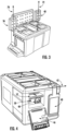
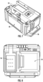
- FIGS. 1-4 depict a stackable device, shown as lighting unit 10.
- Lighting unit 10 includes primary light panel 32, which pivots with respect to housing 62 about axis 34.
- Left-side light panel 36 pivots with respect to housing 62 about axis 38
- right-side light panel 40 pivots with respect to housing 62 about axis 42.
- Primary light panel 32, left-side light panel 36 and right-side light panel 40 each actuate between a retracted position ( FIG. 1 ) and an open position ( FIG. 3 ).
- primary light panel 32 When primary light panel 32 is in the retracted position, primary light panel 32 is pivoted against or near back surface 68 defined by back panel 66.
- left-side light panel 36 when left-side light panel 36 is in the retracted position, left-side light panel 36 is pivoted against or near left-side surface 22 defined by left-side panel 20, and right-side light panel 40 is in the retracted position, right-side light panel 40 is pivoted against or near right-side surface 68 defined by right-side panel 66.
- left-side light panel 36 pivots with respect to housing 62 about axis 38 and is also rotatable about axis 70 ( FIG. 3 ).
- right-side light panel 40 pivots with respect to housing 62 about axis 42 and also rotates about axis 72 ( FIG. 3 ).
- left-side light panel 36 pivots about axis 38 and rotates about axis 70, which are perpendicular to each other.
- right-side light panel 40 pivots about axis 42 and rotates about axis 72, which are perpendicular to each other.
- axis 38 that left-side light panel 36 rotates about is parallel to axis 42 that right-side light panel 40 rotates about, and both axis 38 and axis 42 are perpendicular to axis 34 that primary light panel 32 rotates about.
- Lighting unit 10 includes a top panel 12 that defines top surface 14.
- Top surface 14 comprises one or more coupling components 28, shown as recesses with two ledges that overhang the recesses.
- Coupling components 28 interface with corresponding coupling components on a bottom surface of another unit, such as a storage unit, to couple lighting unit 10 to the storage unit.
- coupling components 28 interface with a storage unit that includes coupling components 30 (e.g., like shown in FIG. 11 ).
- Front panel 16 defines front surface 18 of housing 62.
- Handle 44 protrudes from housing 62 and can be used to carry and/or move lighting unit 10.
- door 46 encloses electrical interface 48, shown as a plug, personal electronic device interface 50, shown as a USB-compatible plug, and compartment 52, which is dimensioned to store a cellular phone being charged via personal electronic device interface 50.
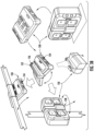
- FIGS. 7-10 depicted are various aspects of lighting unit 10.
- FIGS. 7-8 depict lighting unit 10 with top panel 12 removed.
- FIG. 9 depicts the left-side of lighting unit 10, including door 54.
- Door 54 actuates between a closed position in which battery interface 56 is enclosed, and an open position in battery interface 56 is accessible.
- battery interface 56 is configured to interface with a rechargeable battery for personal power tools (e.g., a battery for a wireless drill).
- the light panels of lighting unit may be illuminated in various combinations as a result of one of a plurality of modes being selected.
- a first mode all three of primary light panel 32, left-side light panel 36 and right-side light panel 40 emit light
- in a second mode only primary light panel 32 emits light and left-side light panel 36 and right-side light panel 40 emit light
- FIG. 11 depicts various aspects of lighting unit 10, including a plurality of coupling components 30.
- Coupling components 30 are configured to interface with the top surface of other units, such as storage units, that include coupling components 28.
- FIG. 12 depicts lighting unit 80.
- Lighting unit 80 is functionally similar to lighting unit 10 except as described herein.
- Lighting unit 80 includes recess 82 from which projections 84 extend.
- projections 84 are configured to receive a power cord that is wrapped around projections 84.
- the panel in left-side light panel 36 and right-side light panel 40 that emits light is 60 mm wide and 100 mm tall, from the perspective of left-side light panel 36 and right-side light panel 40 being in the retracted position.
- the panel in primary light panel 32 that emits light is 280 mm wide and 105 mm tall, from the perspective of primary light panel 32 being in the retracted position.
- the power tool battery and the sidewalls of the battery compartment are 25 mm apart, and the bottom of the power tool battery and the bottom of the battery compartment is 15 mm apart.
- the panels of primary light panel 32, left-side light panel 36 and right-side light panel 40 that emit light include a heat sink (e.g., a 6061 aluminium alloy) behind the light-emitters (e.g., LEDs), a reflector behind the light-emitters (e.g., PC ABS), and a lens in front of the light-emitters.
- a heat sink e.g., a 6061 aluminium alloy
- the light-emitters e.g., LEDs
- a reflector behind the light-emitters e.g., PC ABS
- a lens in front of the light-emitters.
- the lights are selected from the group consisting of an area light (e.g., a light that illuminates 360 degrees), a flood light (e.g., a light that illuminates 180 degrees) and a focused light, such as a task-focused light (e.g., a light that is focused to an angle between 90 degrees and 120 degrees).
- an area light e.g., a light that illuminates 360 degrees
- a flood light e.g., a light that illuminates 180 degrees
- a focused light such as a task-focused light (e.g., a light that is focused to an angle between 90 degrees and 120 degrees).
- lighting unit 10 includes one area light and one task-focused light.
- lighting unit 10 includes one task-focused light and one light selected from the group consisting of an area light and a flood light.
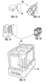
- FIGS. 13-14 illustrate a modular storage system 100 including a light 102 according to one embodiment.
- the lights 102 of FIGS. 13-14 illuminate the path in front of a user while moving the modular storage system 100.
- the light 102 may also be oriented to illuminate a desired area when the modular storage system 100 is stationary.
- the light 102 is configured to emit 300 lumens but other or additional embodiment may emit more or less lumens.
- the light 102 according to the embodiment in FIGS. 13-14 has one or more light-emitting diode (LED) locations that are built into the modular storage system 100.
- LED light-emitting diode
- FIGS. 15-17 illustrate a modular storage system 104 including a light according to another embodiment.
- the lights of FIGS. 15-17 illuminate the path in front of a user while moving the modular storage system 104.
- the light may also be oriented to illuminate a desired area when the modular storage system 104 is stationary.
- the light is configured to emit 300 lumens, but other or additional embodiment may emit more or less lumens.
- the light 106 according to the embodiment of FIGS. 15-17 has one or more light panels 106 that are housed on the sides of the modular storage system, are foldable (e.g., moveable or pivotable) relative to the movable storage system 104, are useable while being transported or while stationary, and are integrated in the full system.
- FIGS. 18-20 illustrate a modular storage system 108 including a light according to another embodiment.
- the light of FIGS. 18-20 can illuminate 360 degrees as an area light or can be a task focused light and have a beam angle of between 90 degrees and 120 degrees.
- the light includes one or more panels 110 (e.g., three panels) that are foldable (e.g., pivotable) and rotatable relative to the modular storage system 108.
- panels 110 e.g., three panels
- foldable e.g., pivotable
- rotatable relative to the modular storage system 108 For example, turning to FIG. 20 in particular, there is a first pivot point to spin each of the light panels 360 degrees and is created by attaching a spindle 112 to the light head and having it protrude down and out of the bottom. Moreover, a threaded part of the spindle 112 is compressed by a threaded washer to create a resistance force when spinning. Also, an up and down fold is created with, for example, wave washers
- FIGS. 21 and 22 illustrates a modular storage system 114 including a light according to another embodiment.
- the light of FIGS. 21 and 22 can illuminate 360 degrees as an area light or can be a task focused light and have a beam angle of between 90 degrees and 120 degrees.
- the light is a dome luminaire that provides task lighting.
- the dome luminaire is movable (e.g., pivotable) relative to the modular storage system.
- FIG. 23 illustrates a modular storage system 116 including a light according to another embodiment.
- the light of FIG. 23 can illuminate 360 degrees as an area light or can be a task focused light and have a beam angle of 120 degrees.
- the light is a main panel 118 that is movable (e.g., pivotable) relative to the modular storage system, and the auxiliary panels fold off (e.g., pivot from) of the main panel.
- FIG. 24 illustrates a modular storage system 120 including a light according to another embodiment.
- the light of FIG. 24 can be transported with the modular storage system 120 and can be integrated into any configuration and location on the system.
- the light is stored on (e.g., coupled to) the top of the modular storage system 120, but in other embodiments, the light may be stored on (e.g., coupled to) other locations of the modular storage system.
- the light may have cleats on the bottom and top of the light allow users to store the light in any configuration of the modular storage system. Alternatively, cleats on the bottom and top of the light allow users to store the light in any configuration of the modular storage system and the light can function/illuminate an area from any of those locations. It is within the scope of this application that in one or more embodiments a user interface (UI) and a battery of the modular storage system are accessible in any location on the modular storage system.
- UI user interface
- FIGS. 25-28 illustrate a modular storage system 122 in which a light functions both on and off the modular storage system. Moreover, the light is capable of attaching to multiple different surfaces or objects by a coupling mechanism.
- the light includes a coupling mechanism that is a clamp, which couples the light to another different surface or object.
- the clamp 124 functions with one or more biasing mechanisms (e.g., springs) that compress as the clamp is pulled away from the light. Once the clamp 124 is around the surface or object, the clamp is released such that it retracts and catches on the surface object thereby holding the light in place.
- the coupling mechanism may include magnets 126 that couple the light to metal surfaces or objects.
- the light may include a handle that allows the user to carry or transport the light on the job site.
- the lights shown and described herein in FIGS. 13-28 have a color temperature of 4000K and a color rendering index (CRI) of at least 80 (e.g., 80+). Moreover, the lights shown and described herein in FIGS. 13-28 can output at least 2500 lumens with a four hour runtime with a 5.0 amp hour battery pack. Additionally, the lights shown and described herein in FIGS. 13-28 can output at least 300 lumen while in a path lighting flood mode with a ten hour runtime with a 5.0 hour battery pack. The lights shown and described herein in FIGS. 13-28 also have a beam angle for area lighting of 360 degrees and task lighting of 90 degrees to 120 degrees.
- CRI color rendering index
- the lights, the modular storage system, or both have an integrated charging system to charge direct current (DC) batteries from an alternative current (AC) power source.
- the system is efficient as well (e.g., LED driver, optic, LED).
- the light is durable in harsh weather conditions and is still able to operate on the job site.
- the light has an indoor storage/ outdoor use product rating. That is, the battery is sealed in a compartment with a gasket.
- the light is IP54 rated.
- the lights shown and described herein in FIGS. 13-28 have thermal dissipation of respective engines thereof with heat sinking.
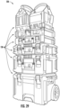
- FIG. 29 illustrates a modular storage system 128 including stackable containers 130, which are movable by one or more wheels.
- FIGS. 30-32 illustrate lights 132 for use with the modular storage system of FIG. 29 .
- the lights have a battery platform. Also, the lights have stacking mechanisms on either or both of the top and the bottom such that that lights can be stacked on one or more of the containers of the modular storage system. In a specific embodiment, the lights consume at least half a width stack.
- the lights are useable while coupled to the modular storage system. All functions (e.g., the battery, controls, lighting, etc.) of the lights are accessible while coupled to the modular storage system.
- the lights are also usable while not coupled to the modular storage system.
- the lights are capable of emitting light in 360 degrees.
- the lights are capable of being powered by direct current (DC), alternating current (AC) or both.
- the lights are easily transportable as well.
- the lights are positionable on the modular storage system. As shown in FIG. 32 , the lights illuminate the path in front of a user while moving the modular storage system. The lights may also be oriented to illuminate a desired area when the modular storage system is stationary. The user has the ability to control light output direction. Moreover, as discussed in greater detail below, the lights are also capable of being coupled to another object such as a pipe, stud, beam, ladder or other object.
- FIG. 33-35 illustrates a light for use with a modular storage system according to another embodiment.
- the light 134 has a head or panel 136 that is movable relative to the modular storage system. That is the head may be pivotable, rotatable, or both relative to the modular storage system.
- FIG. 36 illustrates a light 138 for use with a modular storage system according to another embodiment.
- the light 138 is movably (e.g., pivotably) coupled to a container.
- the light 138 may be positioned in a lid of the container 140 for example. Accordingly, the light 138 may be movable (e.g., pivotable) relative to the container 140 and may be used as a stand. Additionally or alternatively, the light 138 be positioned on a support that is movable (e.g., slideable, pivotable, rotatable) relative to the container.
- the support may be a telescoping support that is movable relative to the container.
- the light 138 may be movable (e.g., slideable, pivotable, rotatable) relative to the support and may also be pivotable or rotatable relative to the container.
- the container 140 may also provide storage space.
- the storage space may be inside the container 140 or outside the container 140.
- the light 138 may include a main panel 142 and auxiliary panels 144 that are coupled and foldable relative to the main panel 142.
- the main panel 142 and auxiliary panels 144 may each be movable (e.g., pivotable or rotatable) to adjust the direction of the light.
- the light 138 is compact, emits light 360 degrees, illuminates the path of the user, and provides storage for small accessories and hand tools.
- the light 138 may be constructed as a tower light or a task light.
- FIG. 37 illustrates a light 146 according to another embodiment.
- the light 146 is movably (e.g., pivotably) coupled to a container 148.
- the light 146 in a first position the light 146 is adjacent the container 148 and in a second position the light 146 is spaced apart from the container 148 by a support.
- the light 146 is movable (e.g., pivotable or rotatable) relative to the container 148 about the support.
- the light 146 may be pivotable or rotatable in two directions (e.g., about two axes).
- the light 146 may be a single panel with light-emitting diodes (LEDs) or multiple panels with LEDs.
- LEDs light-emitting diodes
- the multiple LED panels may be movable or foldable relative to one another.
- lights 146 may be incorporated in a housing of the container 148.
- the container 148 includes a coupling mechanism (e.g., magnets) such that the container 148, with the light 146 can be coupled to an object (e.g., beam or post).
- the light 146 is compact, emits light 360 degrees, illuminates the path of the user, and provides storage for small accessories and hand tools.
- the light 146 may be constructed as a tower light or a task light.
- FIG. 38 illustrates a light 150 according to another embodiment.
- the light 150 includes first and second light panels, which include LEDs 154, and that are movable (e.g., foldable) relative to one another.
- the light 150 also has a handle 156 to make it transportable.
- the light 150 is movably (e.g., pivotably) coupled to a container.
- the container includes a coupling mechanism (e.g., magnets 152) such that the container, with the light, can be coupled to an object (e.g., beam or post).
- the light 150 is compact, emits light 360 degrees, illuminates the path of the user, and provides storage for small accessories and hand tools.
- the light 150 may be constructed as a tower light or a task light. In a specific embodiment the light 150 is powered by battery 158.
- FIG. 39 illustrates a hand-held light for use with the modular storage system.
- the light 160 is positioned or incorporated within an elongate body.
- the elongate body is movably coupled to a housing, which receives a power source (e.g., battery pack).
- a power source e.g., battery pack
- the elongate body is hingedly coupled to the housing.
- the housing may be removably coupled to a container of the modular storage system and therefore the light may be movable or pivotable to the container.
- the elongate body may be formed from or include frosted glass.
- the light 160 is movably coupled to a housing, which is removably coupled to a container of the modular storage system.
- the lights 160 may be coupled to a support, which extends from the housing.
- the lights 160 may be movable (e.g., pivotable or rotatable) about the supports. In the illustrated embodiment, the lights 160 are pivotable about two axes. Additionally or alternatively, the light 160 may be movable or pivotable within the housing about axis 166.
- light 160 and/or battery pack 164 may be stacked on one or more boxes 168.
- the lights 160 are movably (e.g., pivotably or rotatably) coupled to the power source or battery pack 164.
- each of the lights 160 moves (e.g., pivots) to an opposite side of the battery pack.
- the lights 160 may be rotatable about their own axes.
- the lights 160 and battery pack 164 can be selectively placed in slots in the container. That is, the battery pack 164 can be placed in one slot, while the lights 160 may be placed in adjacent slots. The user can alter the configuration of the lights 160 by manipulating or placing the battery pack 164 and lights 160 in various slots in the container.
- the lights 160 may be coupled to the same surface of the battery pack 164 or opposite surfaces of the battery pack.
- the lights 160 are couplable and movable (e.g., pivotable, rotatable) relative to a container of the modular support system, but are also configured to be hand-held.
- the light 160 may have LEDs 162 on a single surface or multiple surfaces.
- the container may have a housing with lights positioned within the housing. Accordingly, the light may provide path illumination or task illumination.
Landscapes
- Engineering & Computer Science (AREA)
- General Engineering & Computer Science (AREA)
- Power Engineering (AREA)
- Mechanical Engineering (AREA)
- Non-Portable Lighting Devices Or Systems Thereof (AREA)
- Arrangement Of Elements, Cooling, Sealing, Or The Like Of Lighting Devices (AREA)
- Fastening Of Light Sources Or Lamp Holders (AREA)
Claims (20)
- Unité d'éclairage empilable (10) configurée pour se coupler à une unité de stockage empilable, l'unité d'éclairage empilable (10) comprenant :un boîtier (62) ;une surface inférieure définie par le boîtier (62), la surface inférieure comprenant des composants de couplage (28) qui couplent de manière détachable la surface inférieure de l'unité d'éclairage empilable (10) à une surface supérieure de l'unité de stockage empilable ; etune première lampe (32, 36, 40) couplée de manière pivotante au boîtier (62), la première lampe (32, 36, 40) étant en rotation pivotante autour d'un premier axe de rotation (38, 42, 70, 72) par rapport au boîtier (62).
- Unité d'éclairage empilable (10) selon la revendication 1, comprenant en outre :une deuxième lampe (32, 36, 40) couplée de manière pivotante au boîtier (62) et la deuxième lampe (32, 36, 40) pivote autour d'un deuxième axe de rotation (38, 42, 70, 72) par rapport au boîtier, le deuxième axe de rotation (38, 42, 70, 72) est distinct du premier axe de rotation (38, 42, 70, 72) ; etune troisième lampe (32, 36, 40) couplée de manière pivotante au boîtier (62) et la troisième lampe (32, 36, 40) pivote autour d'un troisième axe de rotation (38, 42, 70, 72) par rapport au boîtier (62), le troisième axe de rotation (38, 42, 70, 72) est distinct du premier axe de rotation (38, 42, 70, 72) et du deuxième axe de rotation (38, 42, 70, 72).
- Unité d'éclairage empilable (10) selon la revendication 2, dans laquelle le deuxième axe de rotation (38, 42, 70, 72) est perpendiculaire à au moins l'un du premier axe de rotation (38, 42, 70, 72) et du troisième axe de rotation (38, 42, 70, 72).
- Unité d'éclairage empilable (10) selon la revendication 2, comprenant en outre :
une pluralité de modes d'éclairage dans lesquels différentes combinaisons de la première lampe (32, 36, 40), de la deuxième lampe (32, 36, 40), et de la troisième lampe (32, 36, 40) sont allumés lorsque différents modes parmi la pluralité de modes d'éclairage sont sélectionnés. - Unité d'éclairage empilable (10) selon la revendication 1, comprenant en outre :
un panneau supérieur (12) couplé au boîtier opposé à la surface inférieure, dans laquelle la première lampe (32, 36, 40) pivote entre une position ouverte, dans laquelle la première lampe (32, 36, 40) s'étend au-dessus du panneau supérieur (12), et une position rétractée, dans laquelle la première lampe (32, 36, 40) est adjacent à une paroi latérale de l'unité d'éclairage empilable (10). - Unité d'éclairage empilable (10) selon la revendication 4, comprenant en outre :
une languette (64) qui fait saillie de la première lampe (32, 36, 40) lorsque la première lampe (32, 36, 40) est en position rétractée, dans laquelle la languette fait saillie d'une paroi latérale de l'unité d'éclairage empilable. - Unité d'éclairage empilable (10) selon la revendication 1, dans laquelle la première lampe (32, 36, 40) est rotative par rapport au boîtier (62) autour d'un quatrième axe de rotation (38, 42, 70, 72) qui est perpendiculaire au premier axe de rotation (38, 42, 70, 72).
- Unité d'éclairage empilable (10) selon la revendication 1, comprenant en outre :
une deuxième lampe (32, 36, 40) couplée au boîtier (62), dans laquelle la première lampe (32, 36, 40) comprend une lampe focalisée et la deuxième lampe (32, 36, 40) est sélectionnée dans le groupe constitué d'une lampe de zone et d'un projecteur. - Ensemble conteneur (140, 148) comprenant :
une unité d'éclairage comprenant :un premier boîtier ;une surface inférieure définie par le premier boîtier (62), la surface inférieure comprenant un premier composant de couplage (28) ;une première lampe (138) couplée de manière pivotante au premier boîtier, la première lampe (138) tournant de manière pivotante autour d'un premier axe de rotation (166) par rapport au premier boîtier ; et une unité de stockage comprenant :un deuxième boîtier ;un espace de stockage défini au sein du deuxième boîtier ;une surface supérieure définie par le deuxième boîtier, la surface supérieure comprenant un deuxième composant de couplage (30), dans lequel l'unité d'éclairage et l'unité de stockage sont couplées de manière détachable l'une à l'autre via un premier composant de couplage (28) de l'unité d'éclairage en interface avec le deuxième composant de couplage (30) de l'unité de stockage. - Ensemble conteneur (140, 148) selon la revendication 9, comprenant en outre une surface supérieure définie par le premier boîtier, la surface supérieure comprenant un troisième composant de couplage (28), l'ensemble conteneur comprenant en outre :
une seconde unité de stockage comprenant :un troisième boîtier ;un espace de stockage défini au sein du troisième boîtier ;une surface inférieure définie par le troisième boîtier, la surface inférieure comprenant un quatrième composant de couplage (38), dans lequel la surface supérieure de l'unité d'éclairage et la surface inférieure de l'unité de stockage sont couplées l'une à l'autre via le troisième composant de couplage (28) de l'unité d'éclairage en interface avec le quatrième composant de couplage (30) de la seconde unité de stockage. - Ensemble conteneur (140, 148) selon la revendication 9, l'ensemble conteneur (140, 148) comprenant en outre une poignée (44, 156) qui fait saillie latéralement à partir d'une paroi latérale du premier boîtier.
- Ensemble conteneur (140, 148) selon la revendication 9, dans lequel la première lampe (138) est rotative par rapport au premier boîtier de l'unité d'éclairage autour d'un deuxième axe de rotation qui est perpendiculaire au premier axe de rotation.
- Ensemble conteneur (140, 148) selon la revendication 9, comprenant en outre :une deuxième lampe couplée de manière pivotante au premier boîtier de l'unité d'éclairage, la deuxième lampe pivote autour d'un troisième axe de rotation par rapport au premier boîtier de l'unité d'éclairage, dans lequel le troisième axe de rotation est distinct du premier axe de rotation ; etune troisième lampe couplée de manière pivotante au premier boîtier de l'unité d'éclairage, la troisième lampe pivote autour d'un quatrième axe de rotation par rapport au premier boîtier de l'unité d'éclairage, dans lequel le quatrième axe de rotation est distinct du premier axe de rotation et du troisième axe de rotation.
- Ensemble conteneur (140, 148) selon la revendication 13, dans lequel le premier axe de rotation de la première lampe et le quatrième axe de rotation de la troisième lampe sont parallèles.
- Unité d'éclairage empilable (10) configurée pour se coupler à une unité de stockage empilable, l'unité d'éclairage empilable comprenant :un boîtier (62) ;une surface inférieure définie par le boîtier (62), la surface inférieure comprenant des composants de couplage (28) qui couplent la surface inférieure de l'unité de stockage empilable à une surface supérieure d'une unité de stockage empilable, chacun des composants de couplage comprenant un évidement et deux rebords qui surplombent l'évidement ;une première lampe (32, 36, 40) couplée au boîtier (62) ; etune interface de batterie (56) configurée pour se coupler à une batterie d'outil électrique.
- Unité d'éclairage empilable (10) selon la revendication 15, dans laquelle la première lampe (32, 36, 40) pivote autour d'un premier axe de rotation (38, 42, 70, 72) par rapport au boîtier (62).
- Unité d'éclairage empilable (10) selon la revendication 15, comprenant en outre une prise électrique compatible USB.
- Unité d'éclairage empilable (10) selon la revendication 17, comprenant en outre un compartiment de stockage défini au sein du boîtier (62), dans laquelle le compartiment de stockage est dimensionné pour recevoir un téléphone portable.
- Unité d'éclairage empilable (10) selon la revendication 18, comprenant en outre une porte (46) couplée de manière pivotante au boîtier, la porte fonctionnant entre une première position dans laquelle la porte (46) enferme la prise électrique conforme USB et le compartiment de stockage, et une seconde position dans laquelle la prise électrique conforme USB et le compartiment de stockage ne sont pas enfermés par la porte (46).
- Unité d'éclairage empilable (80) selon la revendication 16, comprenant en outre :une surface latérale (22, 68) définie par le boîtier, dans laquelle la surface latérale définit un évidement (82) ; etune pluralité de saillies s'étendant à partir de l'évidement (82), la pluralité de saillies étant configurées pour s'interfacer avec un câble d'alimentation étant stocké à l'intérieur de l'évidement (82).
Priority Applications (1)
| Application Number | Priority Date | Filing Date | Title |
|---|---|---|---|
| EP25174067.6A EP4570441A3 (fr) | 2019-03-06 | 2020-03-04 | Unité de stockage avec composants électroluminescents |
Applications Claiming Priority (3)
| Application Number | Priority Date | Filing Date | Title |
|---|---|---|---|
| US201962814685P | 2019-03-06 | 2019-03-06 | |
| US201962815749P | 2019-03-08 | 2019-03-08 | |
| PCT/US2020/020970 WO2020180978A1 (fr) | 2019-03-06 | 2020-03-04 | Unité de stockage dotée de composants électroluminescents |
Related Child Applications (2)
| Application Number | Title | Priority Date | Filing Date |
|---|---|---|---|
| EP25174067.6A Division EP4570441A3 (fr) | 2019-03-06 | 2020-03-04 | Unité de stockage avec composants électroluminescents |
| EP25174067.6A Division-Into EP4570441A3 (fr) | 2019-03-06 | 2020-03-04 | Unité de stockage avec composants électroluminescents |
Publications (3)
| Publication Number | Publication Date |
|---|---|
| EP3934853A1 EP3934853A1 (fr) | 2022-01-12 |
| EP3934853A4 EP3934853A4 (fr) | 2022-11-09 |
| EP3934853B1 true EP3934853B1 (fr) | 2025-06-18 |
Family
ID=72338746
Family Applications (2)
| Application Number | Title | Priority Date | Filing Date |
|---|---|---|---|
| EP25174067.6A Pending EP4570441A3 (fr) | 2019-03-06 | 2020-03-04 | Unité de stockage avec composants électroluminescents |
| EP20766821.1A Active EP3934853B1 (fr) | 2019-03-06 | 2020-03-04 | Unité de stockage dotée de composants électroluminescents |
Family Applications Before (1)
| Application Number | Title | Priority Date | Filing Date |
|---|---|---|---|
| EP25174067.6A Pending EP4570441A3 (fr) | 2019-03-06 | 2020-03-04 | Unité de stockage avec composants électroluminescents |
Country Status (4)
| Country | Link |
|---|---|
| US (6) | US10962218B2 (fr) |
| EP (2) | EP4570441A3 (fr) |
| CN (2) | CN113518694B (fr) |
| WO (1) | WO2020180978A1 (fr) |
Families Citing this family (51)
| Publication number | Priority date | Publication date | Assignee | Title |
|---|---|---|---|---|
| CN110893610A (zh) * | 2016-05-02 | 2020-03-20 | 凯特尔塑料有限公司 | 实用组件和联接机构 |
| WO2019028041A1 (fr) | 2017-07-31 | 2019-02-07 | Milwaukee Electric Tool Corporation | Système de dispositif de rangement |
| CN111615481B (zh) | 2017-12-20 | 2022-11-04 | 凯特尔塑料有限公司 | 台车及其机械制动系统 |
| CN111867785A (zh) | 2018-01-24 | 2020-10-30 | 米沃奇电动工具公司 | 工具储存装置 |
| IL257294A (en) | 2018-02-01 | 2018-03-29 | Milwaukee Electric Tool Corp | Coupleable crate |
| IL260225A (en) | 2018-06-24 | 2018-07-31 | Keter Plastic Ltd | pushcart |
| CN113518694B (zh) * | 2019-03-06 | 2024-06-18 | 米沃奇电动工具公司 | 具有发光部件的储存单元 |
| IL265964A (en) | 2019-04-11 | 2019-07-31 | Milwaukee Electric Tool Corp | A matching system and adapter for it |
| IL269564B2 (en) | 2019-09-23 | 2023-11-01 | Keter Home & Garden Products Ltd | Sawhorse |
| CN114401863B (zh) * | 2019-09-27 | 2024-05-24 | 米沃奇电动工具公司 | 用于模块化储存的配电 |
| CN212617986U (zh) * | 2019-11-22 | 2021-02-26 | 米沃奇电动工具公司 | 工作灯 |
| CN114728409B (zh) * | 2019-12-13 | 2025-08-01 | 米沃奇电动工具公司 | 储存装置的致动工作表面 |
| CN215362410U (zh) * | 2020-01-20 | 2021-12-31 | 创科无线普通合伙 | 可堆叠存储系统,配合接口以及存储容器 |
| IL274945A (en) * | 2020-05-26 | 2021-12-01 | Keter Plastic Ltd | A set of containers and connectivity for them |
| EP4217654A4 (fr) | 2020-09-24 | 2025-02-12 | Milwaukee Electric Tool Corporation | Systèmes d'éclairage portables |
| DE102020215390A1 (de) * | 2020-12-04 | 2022-06-09 | Festool Gmbh | Tragbare Energiestation, Stapelanordnung und Verfahren zur Herstellung einer tragbaren Energiestation |
| US11913612B2 (en) * | 2021-02-24 | 2024-02-27 | Nanjing Chervon Industry Co., Ltd. | Lighting device |
| US20220290679A1 (en) * | 2021-03-12 | 2022-09-15 | Milwaukee Electric Tool Corporation | Fan assembly |
| US20220376529A1 (en) * | 2021-05-19 | 2022-11-24 | Milwaukee Electric Tool Corporation | Work area charging |
| EP4342641A4 (fr) * | 2021-06-29 | 2024-11-13 | Nanjing Chervon Industry Co., Ltd. | Système de boîte à outils |
| WO2023039198A1 (fr) * | 2021-09-10 | 2023-03-16 | Milwaukee Electric Tool Corporation | Systèmes et procédés pour communiquer sans fil avec un outil électrique rangé |
| US11827415B2 (en) * | 2021-09-16 | 2023-11-28 | Techtronic Cordless Gp | Storage box light |
| US12142935B2 (en) | 2021-10-11 | 2024-11-12 | Ford Global Technologies, Llc | Baseplate inductive electrical connection |
| US12221071B2 (en) | 2021-10-11 | 2025-02-11 | Ford Global Technologies, Llc | Flatbed vehicle accessory assembly and flatbed vehicle cargo management method |
| US12296744B2 (en) | 2021-10-11 | 2025-05-13 | Ford Global Technologies, Llc | Baseplate mounting system with locking mechanism |
| US11964632B2 (en) | 2021-10-11 | 2024-04-23 | Ford Global Technologies, Llc | Vehicle accessory attachment system and attachment method |
| US12184086B2 (en) | 2021-10-11 | 2024-12-31 | Ford Global Technologies, Llc | Baseplate inductive electrical connection system |
| US12269399B2 (en) | 2021-10-11 | 2025-04-08 | Ford Global Technologies, Llc | Baseplate electrical contacts |
| US12344197B2 (en) * | 2021-10-11 | 2025-07-01 | Ford Global Technologies, Llc | Baseplate-based accessory attachment system and attachment method for vehicle |
| US12179956B2 (en) * | 2021-10-15 | 2024-12-31 | Makita U.S.A., Inc. | Modular storage system with storage box connectivity and external box features and accessories |
| WO2023102526A1 (fr) * | 2021-12-03 | 2023-06-08 | Milwaukee Electric Tool Corporation | Unité d'éclairage dans un système modulaire |
| CN114440172B (zh) * | 2022-01-17 | 2022-11-04 | 深圳市联域光电股份有限公司 | 一种照明灯 |
| US12512635B2 (en) * | 2022-01-25 | 2025-12-30 | The Stanley Works Israel Ltd. | Stackable power outlet box |
| US12467607B2 (en) * | 2022-03-11 | 2025-11-11 | Techtronic Cordless Gp | Storage lights and mounting structures for the same |
| US12110032B2 (en) | 2022-07-21 | 2024-10-08 | Ford Global Technologies, Llc | Method and apparatus for estimating stress on a vehicle base plate |
| US12495509B2 (en) | 2022-07-27 | 2025-12-09 | Milwaukee Electric Tool Corporation | Power systems in a modular system |
| USD1087186S1 (en) * | 2022-08-03 | 2025-08-05 | Festool Gmbh | Circular saw with cover |
| US12576789B2 (en) | 2022-08-12 | 2026-03-17 | Ford Global Technologies, Llc | Cargo orientation and alignment |
| US12258075B2 (en) | 2022-08-12 | 2025-03-25 | Ford Global Technologies, Llc | Adjustable base plate |
| US20240077181A1 (en) * | 2022-09-06 | 2024-03-07 | Milwaukee Electric Tool Corporation | Elevated lighting device and storage system |
| US12559019B2 (en) | 2022-11-23 | 2026-02-24 | Ford Global Technologies, Llc | Accessory attachment and locking system for connection to a base plate |
| USD1037522S1 (en) | 2022-11-30 | 2024-07-30 | Eaton Intelligent Power Limited | Floodlight |
| US12570227B2 (en) | 2023-02-08 | 2026-03-10 | Ford Global Technologies, Llc | Accessory base plate with power routing |
| US12539824B2 (en) | 2023-02-15 | 2026-02-03 | Ford Global Technologies, Llc | Locking control system for accessory management |
| TWI829581B (zh) * | 2023-04-19 | 2024-01-11 | 陳王振 | 工具箱 |
| US12565160B2 (en) | 2023-06-07 | 2026-03-03 | Ford Global Technologies, Llc | Accessory base plate with power connection routing |
| US20250003559A1 (en) * | 2023-06-28 | 2025-01-02 | Milwaukee Electric Tool Corporation | Portable area light |
| USD1093896S1 (en) * | 2023-09-07 | 2025-09-23 | Greenworks (Jiangsu) Co., Ltd. | Battery caddie |
| USD1085716S1 (en) * | 2023-10-24 | 2025-07-29 | Ningbo Meiqi Tool Co., Ltd. | Tool box |
| US20250271125A1 (en) * | 2024-02-28 | 2025-08-28 | Milwaukee Electric Tool Corporation | Light assembly for use with a storage system |
| US12570218B2 (en) | 2024-05-29 | 2026-03-10 | Ford Global Technologies, Llc | Track assembly with storage bin |
Family Cites Families (76)
| Publication number | Priority date | Publication date | Assignee | Title |
|---|---|---|---|---|
| US3424334A (en) | 1964-10-09 | 1969-01-28 | Joseph Goltz | Stacking box construction with interlock |
| FR2631928A2 (fr) | 1987-10-27 | 1989-12-01 | Cosmetic Production | Boites pour le conditionnement ou le rangement d'objets divers |
| US4976450A (en) | 1988-02-10 | 1990-12-11 | Ellefson Laurence M | Mobile tool chest with horizontal pivotal trays |
| US6267240B1 (en) | 1996-03-01 | 2001-07-31 | Roscoe Callaway | Illuminated portable tool box |
| US5685421A (en) | 1996-06-28 | 1997-11-11 | Gilmore; Benjamin E. | Storage box for tools and other items |
| US5890613A (en) | 1997-07-21 | 1999-04-06 | Williams; Warren Bret | Modular cooler construction |
| US5779350A (en) | 1997-07-22 | 1998-07-14 | Caster Lighting Inc. | Hand tool case with detachably connected working light |
| US5879072A (en) | 1998-03-13 | 1999-03-09 | Huang; Yung Hsu | Tool box having a light device |
| US6223899B1 (en) | 1999-12-29 | 2001-05-01 | Tsai-Chien Shih | Tool box assembly having lighting and warning functions |
| US20020179472A1 (en) | 2001-05-30 | 2002-12-05 | Hsiu-Yueh Lee | Tool box having an upright standing portion |
| US7714708B2 (en) * | 2001-12-28 | 2010-05-11 | Brackmann Rogers F | Smart pallet-box cargo container |
| FR2834824B1 (fr) | 2002-01-15 | 2004-04-02 | Entrelec | Dispositif de connexion d'un boitier electronique |
| US6981780B2 (en) | 2002-12-31 | 2006-01-03 | Zag Industries Ltd. | Tool box with light |
| US6983946B2 (en) | 2003-04-01 | 2006-01-10 | Porta Plastic Products | Transportable containers apparatus and method |
| JP2008516855A (ja) | 2004-10-15 | 2008-05-22 | フードキャップ インターナショナル リミテッド | コンテナ、蓋体およびそのためのクリップ |
| US7503569B2 (en) | 2005-05-16 | 2009-03-17 | Keter Plastic Ltd. | Portable container assembly |
| US7252404B1 (en) | 2005-08-19 | 2007-08-07 | Messamore Douglas J | Toolbox with power supply |
| US20070138041A1 (en) | 2005-12-19 | 2007-06-21 | Welsh Robert P | Carrying Case |
| CN200948587Y (zh) | 2006-09-11 | 2007-09-19 | 张明吉 | 工具盒 |
| US7470036B2 (en) * | 2007-03-28 | 2008-12-30 | Pelican Products, Inc. | Lighting system |
| US7484858B2 (en) | 2007-03-28 | 2009-02-03 | Pelican Products, Inc. | Lighting system |
| US8084992B2 (en) | 2007-05-08 | 2011-12-27 | Snap-On Incorporated | Tool storage cabinet having integrated power |
| US7731398B2 (en) * | 2007-10-04 | 2010-06-08 | Probasco Design | Portable lightbox assembly |
| US20100085745A1 (en) | 2008-10-07 | 2010-04-08 | Keith Kristiansen | Portable storage container with lamp assembly |
| CN201471421U (zh) | 2009-06-24 | 2010-05-19 | 赖国荣 | 太阳能充电工具箱 |
| DE102009027573A1 (de) | 2009-07-09 | 2011-01-13 | Robert Bosch Gmbh | Werkzeugkoffer, insbesondere Handwerkzeugkoffer |
| US9132543B2 (en) | 2009-09-01 | 2015-09-15 | The Stanley Works Israel Ltd. | Rolling container assembly with adjustable storage units |
| US8567796B2 (en) | 2009-09-01 | 2013-10-29 | The Stanley Works Israel Ltd. | Rolling container assembly with adjustable storage units |
| EP2338650B1 (fr) | 2009-12-25 | 2016-10-19 | Makita Corporation | Boîtier de stockage d'outil électrique |
| US20130051080A1 (en) | 2010-02-25 | 2013-02-28 | Demain Technology Pty Ltd | Power station assembly |
| WO2011103638A1 (fr) | 2010-02-25 | 2011-09-01 | Demain Technology Pty Ltd | Système de stockage et de conditionnement d'outil électrique |
| US20110260588A1 (en) | 2010-04-27 | 2011-10-27 | Chia-Yun Lin | Tool Cabinet |
| DE102011002409A1 (de) | 2010-05-27 | 2011-12-01 | Robert Bosch Gmbh | Handwerkzeugkoffer |
| DE102011006871B4 (de) | 2011-01-03 | 2024-08-08 | Robert Bosch Gmbh | Handwerkzeugkoffer mit einer Leuchtvorrichtung |
| DE102011007785A1 (de) * | 2011-04-20 | 2012-10-25 | Robert Bosch Gmbh | Handwerkzeugaufbewahrungsvorrichtung |
| DE102011077112B4 (de) | 2011-06-07 | 2024-07-25 | Robert Bosch Gmbh | Handwerkzeugaufbewahrungsvorrichtung |
| US8657307B2 (en) | 2011-06-22 | 2014-02-25 | The Stanley Works Israel Ltd. | Modular rolling container assembly |
| EP2596920B1 (fr) | 2011-11-22 | 2018-06-06 | The Stanley Works Israel Ltd. | Ensemble conteneur modulaire |
| US8740010B1 (en) | 2012-01-19 | 2014-06-03 | Rex E. Page | Cooler with locking capabilities |
| US20130186795A1 (en) | 2012-01-23 | 2013-07-25 | Scott Borrelli | Tray Case |
| WO2014125484A1 (fr) | 2013-02-14 | 2014-08-21 | Keter Plastic Ltd. | Boîte à outils |
| US20140265440A1 (en) | 2013-03-14 | 2014-09-18 | Kung-Cheng Chen | Cart having corner bumpers, side containers, and corner top holders |
| DE102013205416A1 (de) | 2013-03-27 | 2014-10-16 | Robert Bosch Gmbh | Akkubetriebene Leuchteinheit |
| US20140332423A1 (en) | 2013-05-07 | 2014-11-13 | Hong-Jen Lee | Tool box |
| DE202014103695U1 (de) | 2014-04-24 | 2014-10-30 | Metabowerke Gmbh | Stapelbarer Behälter |
| US10575417B2 (en) | 2014-09-08 | 2020-02-25 | The Stanley Works Israel Ltd. | Jobsite communications center |
| CN204354100U (zh) | 2014-11-13 | 2015-05-27 | 王伟 | 多功能测绘工具箱 |
| DE102015200382A1 (de) | 2015-01-14 | 2016-07-14 | Robert Bosch Gmbh | Vorrichtung zur Aufbewahrung eines Handwerkzeugs, insbesondereHandwerkzeugaufbewahrungsvorrichtung, mit zumindest einer Grundkörpereinheit |
| US9566704B1 (en) | 2015-01-21 | 2017-02-14 | Christopher Stoikos | Toolbox |
| CN204725472U (zh) | 2015-05-19 | 2015-10-28 | 宁波唯嘉电子科技有限公司 | 一种方便使用的工具盒 |
| CN104842331A (zh) * | 2015-05-22 | 2015-08-19 | 国网河南省电力公司电力科学研究院 | 一种实现移动电源及光源的多功能工具箱 |
| CN204640191U (zh) | 2015-05-22 | 2015-09-16 | 国网河南省电力公司电力科学研究院 | 一种实现移动电源及光源的多功能工具箱 |
| US9375835B1 (en) | 2015-07-29 | 2016-06-28 | Fairness Technology Corp. | Tool box assembly |
| DE202015005752U1 (de) | 2015-08-18 | 2016-11-21 | Plaston Ag | Stapelbarer Koffer mit Kopplungsverbindung und Sicherung |
| CN105082096B (zh) | 2015-09-02 | 2016-11-30 | 姚文篡 | 带照明的工具箱 |
| CN105328673B (zh) | 2015-11-27 | 2017-09-26 | 国网浙江省电力公司磐安县供电公司 | 一种电力工具收纳箱 |
| CN205111818U (zh) | 2015-11-27 | 2016-03-30 | 国网浙江省电力公司磐安县供电公司 | 一种电力工具收纳箱 |
| DE102016105458A1 (de) * | 2016-01-07 | 2017-07-13 | Festool Gmbh | Übertragungseinrichtung und damit ausgestatteter Stapelbehälter |
| US11215353B2 (en) | 2017-02-14 | 2022-01-04 | Milwaukee Electric Tool Corporation | Job box |
| CN206632975U (zh) * | 2017-04-19 | 2017-11-14 | 吴祝强 | 一种多功能工具盒 |
| CN206795769U (zh) | 2017-05-10 | 2017-12-26 | 冯峰 | 新型电力维修箱 |
| CN206998861U (zh) | 2017-06-01 | 2018-02-13 | 北京赢和睿致科技有限责任公司 | 军用维修工具箱 |
| CN107309852A (zh) | 2017-08-10 | 2017-11-03 | 滨州市金毅设备有限公司 | 一种救援沙滩车用多功能工具箱 |
| EP3692298B1 (fr) * | 2017-10-06 | 2022-12-07 | Milwaukee Electric Tool Corporation | Lampe de chantier |
| US10677738B2 (en) * | 2017-10-16 | 2020-06-09 | Hail Spotter L.L.C | Collapsible light tunnel |
| CN108224129A (zh) | 2018-03-02 | 2018-06-29 | 电子科技大学中山学院 | 一种手持式工程箱灯 |
| CN207921804U (zh) | 2018-03-02 | 2018-09-28 | 电子科技大学中山学院 | 一种手持式工程箱灯 |
| CN108858100A (zh) * | 2018-05-17 | 2018-11-23 | 安徽凯密克企业管理咨询有限公司 | 一种便于调节照明角度的建筑工程工具存放装置 |
| IL260225A (en) * | 2018-06-24 | 2018-07-31 | Keter Plastic Ltd | pushcart |
| CN209063055U (zh) | 2018-09-09 | 2019-07-05 | 陈志钦 | 一种电力工具箱 |
| CN209111035U (zh) | 2018-12-06 | 2019-07-16 | 青岛八面通装饰工程有限公司 | 一种用于工程设计的便携式工具箱 |
| CN113518694B (zh) * | 2019-03-06 | 2024-06-18 | 米沃奇电动工具公司 | 具有发光部件的储存单元 |
| US10663124B1 (en) * | 2019-06-11 | 2020-05-26 | Donald Smith | Portable light stand assembly |
| US10663150B1 (en) * | 2019-06-25 | 2020-05-26 | Phillip Luna | Hands-free forearm flashlight having a base with hinge and light panel coupled to hinge with strap coupled to the base |
| CN220287307U (zh) * | 2020-09-24 | 2024-01-02 | 米沃奇电动工具公司 | 便携式照明系统 |
| WO2023102526A1 (fr) * | 2021-12-03 | 2023-06-08 | Milwaukee Electric Tool Corporation | Unité d'éclairage dans un système modulaire |
-
2020
- 2020-03-04 CN CN202080017622.9A patent/CN113518694B/zh active Active
- 2020-03-04 EP EP25174067.6A patent/EP4570441A3/fr active Pending
- 2020-03-04 US US16/809,287 patent/US10962218B2/en active Active
- 2020-03-04 WO PCT/US2020/020970 patent/WO2020180978A1/fr not_active Ceased
- 2020-03-04 EP EP20766821.1A patent/EP3934853B1/fr active Active
- 2020-03-04 CN CN202410670666.1A patent/CN118442570A/zh active Pending
-
2021
- 2021-02-19 US US17/180,328 patent/US11268691B2/en active Active
-
2022
- 2022-03-04 US US17/687,129 patent/US11662090B2/en active Active
-
2023
- 2023-04-24 US US18/305,939 patent/US11959629B2/en active Active
-
2024
- 2024-03-22 US US18/613,561 patent/US12270537B2/en active Active
-
2025
- 2025-03-10 US US19/075,427 patent/US20250207771A1/en active Pending
Also Published As
| Publication number | Publication date |
|---|---|
| US20220186922A1 (en) | 2022-06-16 |
| US20210172595A1 (en) | 2021-06-10 |
| CN118442570A (zh) | 2024-08-06 |
| US20200284425A1 (en) | 2020-09-10 |
| US11268691B2 (en) | 2022-03-08 |
| US11662090B2 (en) | 2023-05-30 |
| US20230258325A1 (en) | 2023-08-17 |
| EP3934853A1 (fr) | 2022-01-12 |
| EP4570441A2 (fr) | 2025-06-18 |
| CN113518694A (zh) | 2021-10-19 |
| EP3934853A4 (fr) | 2022-11-09 |
| CN113518694B (zh) | 2024-06-18 |
| US20250207771A1 (en) | 2025-06-26 |
| US20240230080A1 (en) | 2024-07-11 |
| US10962218B2 (en) | 2021-03-30 |
| EP4570441A3 (fr) | 2025-12-03 |
| US11959629B2 (en) | 2024-04-16 |
| US12270537B2 (en) | 2025-04-08 |
| WO2020180978A1 (fr) | 2020-09-10 |
Similar Documents
| Publication | Publication Date | Title |
|---|---|---|
| EP3934853B1 (fr) | Unité de stockage dotée de composants électroluminescents | |
| US9091401B2 (en) | Work light | |
| US6254251B1 (en) | Portable tool storage box | |
| US11493177B2 (en) | Task-area light | |
| EP3990821B1 (fr) | Lampe sur pieds | |
| US8770778B2 (en) | Utility light kit for attachment to the top of a ladder | |
| JP4162696B1 (ja) | ソーラー式ポータブル発電ユニット | |
| EP4269033B1 (fr) | Outil électrique | |
| WO2022067072A1 (fr) | Systèmes d'éclairage portables | |
| JP5079617B2 (ja) | ソーラー式ポータブル発電器具 | |
| US20180224102A1 (en) | Methods and apparatus for a multi-functional foldable thin light | |
| EP2529147A2 (fr) | Projecteur pliable | |
| CN220287307U (zh) | 便携式照明系统 | |
| CA2930317C (fr) | Lampe de poche | |
| JP3135507U (ja) | ソーラー式ポータブル発電ユニット | |
| US20250251099A1 (en) | Lighting device |
Legal Events
| Date | Code | Title | Description |
|---|---|---|---|
| STAA | Information on the status of an ep patent application or granted ep patent |
Free format text: STATUS: THE INTERNATIONAL PUBLICATION HAS BEEN MADE |
|
| PUAI | Public reference made under article 153(3) epc to a published international application that has entered the european phase |
Free format text: ORIGINAL CODE: 0009012 |
|
| STAA | Information on the status of an ep patent application or granted ep patent |
Free format text: STATUS: REQUEST FOR EXAMINATION WAS MADE |
|
| 17P | Request for examination filed |
Effective date: 20210916 |
|
| AK | Designated contracting states |
Kind code of ref document: A1 Designated state(s): AL AT BE BG CH CY CZ DE DK EE ES FI FR GB GR HR HU IE IS IT LI LT LU LV MC MK MT NL NO PL PT RO RS SE SI SK SM TR |
|
| DAV | Request for validation of the european patent (deleted) | ||
| DAX | Request for extension of the european patent (deleted) | ||
| A4 | Supplementary search report drawn up and despatched |
Effective date: 20221010 |
|
| RIC1 | Information provided on ipc code assigned before grant |
Ipc: F21V 21/14 20060101ALI20221004BHEP Ipc: F21V 33/00 20060101ALI20221004BHEP Ipc: B25H 3/02 20060101AFI20221004BHEP |
|
| GRAP | Despatch of communication of intention to grant a patent |
Free format text: ORIGINAL CODE: EPIDOSNIGR1 |
|
| STAA | Information on the status of an ep patent application or granted ep patent |
Free format text: STATUS: GRANT OF PATENT IS INTENDED |
|
| INTG | Intention to grant announced |
Effective date: 20250120 |
|
| RIN1 | Information on inventor provided before grant (corrected) |
Inventor name: ASHER, MATTHEW Inventor name: CHAN, SAN SANG Inventor name: MATTHEWS, MICHAEL A. Inventor name: SELF, ZACHARY J. Inventor name: PLATO, LEA M. |
|
| GRAS | Grant fee paid |
Free format text: ORIGINAL CODE: EPIDOSNIGR3 |
|
| GRAA | (expected) grant |
Free format text: ORIGINAL CODE: 0009210 |
|
| STAA | Information on the status of an ep patent application or granted ep patent |
Free format text: STATUS: THE PATENT HAS BEEN GRANTED |
|
| AK | Designated contracting states |
Kind code of ref document: B1 Designated state(s): AL AT BE BG CH CY CZ DE DK EE ES FI FR GB GR HR HU IE IS IT LI LT LU LV MC MK MT NL NO PL PT RO RS SE SI SK SM TR |
|
| REG | Reference to a national code |
Ref country code: GB Ref legal event code: FG4D |
|
| REG | Reference to a national code |
Ref country code: CH Ref legal event code: EP |
|
| REG | Reference to a national code |
Ref country code: DE Ref legal event code: R096 Ref document number: 602020052965 Country of ref document: DE |
|
| REG | Reference to a national code |
Ref country code: CH Ref legal event code: EP |
|
| REG | Reference to a national code |
Ref country code: IE Ref legal event code: FG4D |
|
| P01 | Opt-out of the competence of the unified patent court (upc) registered |
Free format text: CASE NUMBER: APP_31362/2025 Effective date: 20250630 |
|
| PG25 | Lapsed in a contracting state [announced via postgrant information from national office to epo] |
Ref country code: FI Free format text: LAPSE BECAUSE OF FAILURE TO SUBMIT A TRANSLATION OF THE DESCRIPTION OR TO PAY THE FEE WITHIN THE PRESCRIBED TIME-LIMIT Effective date: 20250618 |
|
| REG | Reference to a national code |
Ref country code: LT Ref legal event code: MG9D |
|
| PG25 | Lapsed in a contracting state [announced via postgrant information from national office to epo] |
Ref country code: NO Free format text: LAPSE BECAUSE OF FAILURE TO SUBMIT A TRANSLATION OF THE DESCRIPTION OR TO PAY THE FEE WITHIN THE PRESCRIBED TIME-LIMIT Effective date: 20250918 Ref country code: GR Free format text: LAPSE BECAUSE OF FAILURE TO SUBMIT A TRANSLATION OF THE DESCRIPTION OR TO PAY THE FEE WITHIN THE PRESCRIBED TIME-LIMIT Effective date: 20250919 |
|
| PG25 | Lapsed in a contracting state [announced via postgrant information from national office to epo] |
Ref country code: BG Free format text: LAPSE BECAUSE OF FAILURE TO SUBMIT A TRANSLATION OF THE DESCRIPTION OR TO PAY THE FEE WITHIN THE PRESCRIBED TIME-LIMIT Effective date: 20250618 |
|
| PG25 | Lapsed in a contracting state [announced via postgrant information from national office to epo] |
Ref country code: HR Free format text: LAPSE BECAUSE OF FAILURE TO SUBMIT A TRANSLATION OF THE DESCRIPTION OR TO PAY THE FEE WITHIN THE PRESCRIBED TIME-LIMIT Effective date: 20250618 |
|
| PG25 | Lapsed in a contracting state [announced via postgrant information from national office to epo] |
Ref country code: RS Free format text: LAPSE BECAUSE OF FAILURE TO SUBMIT A TRANSLATION OF THE DESCRIPTION OR TO PAY THE FEE WITHIN THE PRESCRIBED TIME-LIMIT Effective date: 20250918 |
|
| REG | Reference to a national code |
Ref country code: NL Ref legal event code: MP Effective date: 20250618 |
|
| PG25 | Lapsed in a contracting state [announced via postgrant information from national office to epo] |
Ref country code: LV Free format text: LAPSE BECAUSE OF FAILURE TO SUBMIT A TRANSLATION OF THE DESCRIPTION OR TO PAY THE FEE WITHIN THE PRESCRIBED TIME-LIMIT Effective date: 20250618 |
|
| PG25 | Lapsed in a contracting state [announced via postgrant information from national office to epo] |
Ref country code: NL Free format text: LAPSE BECAUSE OF FAILURE TO SUBMIT A TRANSLATION OF THE DESCRIPTION OR TO PAY THE FEE WITHIN THE PRESCRIBED TIME-LIMIT Effective date: 20250618 |
|
| PG25 | Lapsed in a contracting state [announced via postgrant information from national office to epo] |
Ref country code: PT Free format text: LAPSE BECAUSE OF FAILURE TO SUBMIT A TRANSLATION OF THE DESCRIPTION OR TO PAY THE FEE WITHIN THE PRESCRIBED TIME-LIMIT Effective date: 20251020 |
|
| REG | Reference to a national code |
Ref country code: AT Ref legal event code: MK05 Ref document number: 1803798 Country of ref document: AT Kind code of ref document: T Effective date: 20250618 |
|
| PG25 | Lapsed in a contracting state [announced via postgrant information from national office to epo] |
Ref country code: IS Free format text: LAPSE BECAUSE OF FAILURE TO SUBMIT A TRANSLATION OF THE DESCRIPTION OR TO PAY THE FEE WITHIN THE PRESCRIBED TIME-LIMIT Effective date: 20251018 |
|
| PG25 | Lapsed in a contracting state [announced via postgrant information from national office to epo] |
Ref country code: SM Free format text: LAPSE BECAUSE OF FAILURE TO SUBMIT A TRANSLATION OF THE DESCRIPTION OR TO PAY THE FEE WITHIN THE PRESCRIBED TIME-LIMIT Effective date: 20250618 Ref country code: AT Free format text: LAPSE BECAUSE OF FAILURE TO SUBMIT A TRANSLATION OF THE DESCRIPTION OR TO PAY THE FEE WITHIN THE PRESCRIBED TIME-LIMIT Effective date: 20250618 |
|
| PG25 | Lapsed in a contracting state [announced via postgrant information from national office to epo] |
Ref country code: CZ Free format text: LAPSE BECAUSE OF FAILURE TO SUBMIT A TRANSLATION OF THE DESCRIPTION OR TO PAY THE FEE WITHIN THE PRESCRIBED TIME-LIMIT Effective date: 20250618 |
|
| PG25 | Lapsed in a contracting state [announced via postgrant information from national office to epo] |
Ref country code: PL Free format text: LAPSE BECAUSE OF FAILURE TO SUBMIT A TRANSLATION OF THE DESCRIPTION OR TO PAY THE FEE WITHIN THE PRESCRIBED TIME-LIMIT Effective date: 20250618 |
|
| PG25 | Lapsed in a contracting state [announced via postgrant information from national office to epo] |
Ref country code: EE Free format text: LAPSE BECAUSE OF FAILURE TO SUBMIT A TRANSLATION OF THE DESCRIPTION OR TO PAY THE FEE WITHIN THE PRESCRIBED TIME-LIMIT Effective date: 20250618 |
|
| PG25 | Lapsed in a contracting state [announced via postgrant information from national office to epo] |
Ref country code: SK Free format text: LAPSE BECAUSE OF FAILURE TO SUBMIT A TRANSLATION OF THE DESCRIPTION OR TO PAY THE FEE WITHIN THE PRESCRIBED TIME-LIMIT Effective date: 20250618 Ref country code: RO Free format text: LAPSE BECAUSE OF FAILURE TO SUBMIT A TRANSLATION OF THE DESCRIPTION OR TO PAY THE FEE WITHIN THE PRESCRIBED TIME-LIMIT Effective date: 20250618 |
|
| PG25 | Lapsed in a contracting state [announced via postgrant information from national office to epo] |
Ref country code: ES Free format text: LAPSE BECAUSE OF FAILURE TO SUBMIT A TRANSLATION OF THE DESCRIPTION OR TO PAY THE FEE WITHIN THE PRESCRIBED TIME-LIMIT Effective date: 20250618 |
|
| REG | Reference to a national code |
Ref country code: DE Ref legal event code: R097 Ref document number: 602020052965 Country of ref document: DE |
|
| PGFP | Annual fee paid to national office [announced via postgrant information from national office to epo] |
Ref country code: GB Payment date: 20260327 Year of fee payment: 7 |
|
| PG25 | Lapsed in a contracting state [announced via postgrant information from national office to epo] |
Ref country code: DK Free format text: LAPSE BECAUSE OF FAILURE TO SUBMIT A TRANSLATION OF THE DESCRIPTION OR TO PAY THE FEE WITHIN THE PRESCRIBED TIME-LIMIT Effective date: 20250618 |
|
| PGFP | Annual fee paid to national office [announced via postgrant information from national office to epo] |
Ref country code: DE Payment date: 20260327 Year of fee payment: 7 |
|
| PG25 | Lapsed in a contracting state [announced via postgrant information from national office to epo] |
Ref country code: IT Free format text: LAPSE BECAUSE OF FAILURE TO SUBMIT A TRANSLATION OF THE DESCRIPTION OR TO PAY THE FEE WITHIN THE PRESCRIBED TIME-LIMIT Effective date: 20250618 |
|
| PLBE | No opposition filed within time limit |
Free format text: ORIGINAL CODE: 0009261 |
|
| STAA | Information on the status of an ep patent application or granted ep patent |
Free format text: STATUS: NO OPPOSITION FILED WITHIN TIME LIMIT |
|
| REG | Reference to a national code |
Ref country code: CH Ref legal event code: L10 Free format text: ST27 STATUS EVENT CODE: U-0-0-L10-L00 (AS PROVIDED BY THE NATIONAL OFFICE) Effective date: 20260430 |