EP3934983B1 - Dispositif et procédé de couplage androgyne et utilisation associée - Google Patents
Dispositif et procédé de couplage androgyne et utilisation associée Download PDFInfo
- Publication number
- EP3934983B1 EP3934983B1 EP20725411.1A EP20725411A EP3934983B1 EP 3934983 B1 EP3934983 B1 EP 3934983B1 EP 20725411 A EP20725411 A EP 20725411A EP 3934983 B1 EP3934983 B1 EP 3934983B1
- Authority
- EP
- European Patent Office
- Prior art keywords
- coupling
- coupling means
- androgynous
- ring
- axial
- Prior art date
- Legal status (The legal status is an assumption and is not a legal conclusion. Google has not performed a legal analysis and makes no representation as to the accuracy of the status listed.)
- Active
Links
Images






Classifications
-
- F—MECHANICAL ENGINEERING; LIGHTING; HEATING; WEAPONS; BLASTING
- F16—ENGINEERING ELEMENTS AND UNITS; GENERAL MEASURES FOR PRODUCING AND MAINTAINING EFFECTIVE FUNCTIONING OF MACHINES OR INSTALLATIONS; THERMAL INSULATION IN GENERAL
- F16B—DEVICES FOR FASTENING OR SECURING CONSTRUCTIONAL ELEMENTS OR MACHINE PARTS TOGETHER, e.g. NAILS, BOLTS, CIRCLIPS, CLAMPS, CLIPS OR WEDGES; JOINTS OR JOINTING
- F16B21/00—Means for preventing relative axial movement of a pin, spigot, shaft or the like and a member surrounding it; Stud-and-socket releasable fastenings
- F16B21/02—Releasable fastening devices locking by rotation
- F16B21/04—Releasable fastening devices locking by rotation with bayonet catch
-
- B—PERFORMING OPERATIONS; TRANSPORTING
- B64—AIRCRAFT; AVIATION; COSMONAUTICS
- B64G—COSMONAUTICS; VEHICLES OR EQUIPMENT THEREFOR
- B64G1/00—Cosmonautic vehicles
- B64G1/22—Parts of, or equipment specially adapted for fitting in or to, cosmonautic vehicles
- B64G1/64—Systems for coupling or separating cosmonautic vehicles or parts thereof, e.g. docking arrangements
- B64G1/646—Docking or rendezvous systems
- B64G1/6462—Docking or rendezvous systems characterised by the means for engaging other vehicles
-
- H—ELECTRICITY
- H01—ELECTRIC ELEMENTS
- H01R—ELECTRICALLY-CONDUCTIVE CONNECTIONS; STRUCTURAL ASSOCIATIONS OF A PLURALITY OF MUTUALLY-INSULATED ELECTRICAL CONNECTING ELEMENTS; COUPLING DEVICES; CURRENT COLLECTORS
- H01R13/00—Details of coupling devices of the kinds covered by groups H01R12/70 or H01R24/00 - H01R33/00
- H01R13/62—Means for facilitating engagement or disengagement of coupling parts or for holding them in engagement
- H01R13/627—Snap or like fastening
- H01R13/6276—Snap or like fastening comprising one or more balls engaging in a hole or a groove
-
- H—ELECTRICITY
- H01—ELECTRIC ELEMENTS
- H01R—ELECTRICALLY-CONDUCTIVE CONNECTIONS; STRUCTURAL ASSOCIATIONS OF A PLURALITY OF MUTUALLY-INSULATED ELECTRICAL CONNECTING ELEMENTS; COUPLING DEVICES; CURRENT COLLECTORS
- H01R24/00—Two-part coupling devices, or either of their cooperating parts, characterised by their overall structure
- H01R24/84—Hermaphroditic coupling devices
Definitions
- the present invention refers to an androgynous coupling means as well as to androgynous couplings.
- the present invention further refers to a method of androgynous coupling.
- the present invention refers to the use of such androgynous coupling means, especially for modular satellites, in/for connectors and/or robots.
- the present invention further refers to methods and devices according to the independent claims.
- Androgynous couplings see US 5 658 159 A , allow for safe and robust coupling methods in many applications. Nonetheless, androgynous coupling devices may require quite sophisticated techniques. Thus, for many applications good results may be provided by an androgynous coupling which may ensure a robust and practical way of coupling, without being unreasonably sophisticated in view of technical requirements.
- US 6,354,540 B1 describes an androgynous coupling with an active side and a passive side, wherein the active side may be adjusted by means of a plurality of actuators during coupling.
- the coupling process is a purely mechanical coupling process.
- the forces are applied especially at the free ends of the coupling means, i.e., by means of male and female coupling sections.
- the process of coupling may be initiated or actuated by motors/actuators, e.g. electrical actuators arranged within a cavity of the respective coupling means, especially centrally arranged.
- corresponding generally designates any element/component ,,...of the corresponding coupling element.
- the term “element” generally designates any separate component in the coupling mechanism, but does not restrict any structure or component to integral one-piece components. Rather, the term “element” may also designate components being composed of several constituent parts.
- blocking generally designates any preferably reversible mechanical coupling which allows transfer of mechanical loads by means of preferably reversible coupling. For example, this can be achieved by movable balls which can be guided and forced into a locking position, especially in a relative radial blocking position.
- push-push generally designates any mechanism which allows actuation based on successive relative motion in one direction, especially against preload.
- push-pull generally designates any mechanism which allows actuation based on successive relative motion in two opposed directions.
- corresponding element generally designates the analog element of the corresponding coupling partner.
- force fit generally designates joints or connections which can be ensured based on forces between the connecting parts.
- friction fit generally designates force fit by friction forces, e.g. surface forces on radial and/or axial and/or circumferential direction.
- self-locking generally designates any mechanism which allows for a locking function per se, without any active mechanism, especially by form fit and/or friction fit.
- preload generally designates any tension or pre-stressing force or pre-load or momentum which is exerted on a machine part, the machine part being in a fixed position or being movable.
- cam-curve or “cam-contour” generally designates any guiding surface configured to define a relative position depending on relative motion in radial and/or axial and/or circumferential direction.
- cam-curve may refer both to contours which guide from one side only (so called open contours) and contours which guide from two sides (so called closed contours).
- the term “gear” generally designates any component allowing for coupling machine parts and changing their relative speeds and/or their direction and consequently, the transmitted torque.
- motor generally designates any actuator configured for generating energy and/or motion.
- the term "sensor” generally designates any measuring device for at least one measuring parameter which allows for monitoring the coupling process, for example a force parameter, or a momentum parameter, or a position parameter.
- edge generally designates any inclined geometry or contour which is arranged for exerting a force or relative displacement in a second direction when actuated in a first direction.
- the male and female coupling sections may provide a kind of saw tooth profile or a saw tooth tread design, i.e., alternating convex and concave sections.
- the protruding (male) sections as well as the recesses (female sections) are provided in a small number only, e.g. each three or four or five times along the circumference of the coupling means.
- the teeth or protrusions (male sections) as well as the recesses (female sections) respectively exhibit a symmetrical shape at least in both circumferential directions.
- the male and female coupling sections may exhibit at least one planar area.
- the male and female coupling sections may exhibit several surface areas arranged at an angle different than 0° with respect to each other, especially several planar areas.
- the androgynous coupling means may exhibit a central docking area, wherein the male and female coupling sections encircle the central docking area in a circumferential manner.
- the male and female coupling sections may alternate in a/the circumferential direction.
- the male and female coupling sections may extend radially towards the center (at least approximately).
- the central area may be a cavity.
- the male coupling sections may axially protrude from a/the central docking area of the androgynous coupling means, the male coupling sections especially being arranged adjacent the central docking area.
- the female coupling sections can be configured as axial recesses arranged adjacent the central docking area of the androgynous coupling means. Nonetheless, the exact location of the respective coupling sections may be designed individually for specific applications.
- the invention allows for the transmission of considerable forces and torques especially since force transmission may be carried out along the outer edges (outer area) of the coupling, i.e., far from the fulcrum. Also, the invention may ensure high stability regarding forces and/or mechanical loads, e.g. bending forces, compression forces, traction forces, shearing forces and/or twist loads.
- the inventive arrangement also allows for advantageous disposition of components and elements (connections, interfaces, lines or cables for power, data or fluids) within the coupling. These components are protected from water, dirt, or other aggressive, abrasive or corrosive materials. Depending on an appropriate choice of materials, further, an insulation and/or shielding against magnetic or electro-magnetic fields, temperature and/or radiation can also be achieved.
- the inventive constructive arrangement (coupling design) allows for good shielding thanks to a ring-in-ring-arrangement without occupying additional space which is especially useful for applications in which axial length is limited.
- the male and female coupling sections can be geometrically configured in a mirror-inverted manner, especially along the axial direction.
- the androgynous coupling means is configured for a ring-in-ring-arrangement of a plurality of axially guiding rings. This also allows for robustness.
- the androgynous coupling means may exhibit a base body providing a ring cavity for accommodating and axially guiding the blocking elements. This may favour support of the blocking elements as well as advantageous flux of forces.
- the base body's ring cavity may also provide accommodation for an outer ring and/or at least one positioning ring (especially wedge ring). Such an arrangement has been found to be advantageous both in view of volume requirements and precision (especially guiding accuracy).
- the radial recess may be arranged within the radial extension of a/the base body of the androgynous coupling means. This allows for favorable arrangement and support of several components of the coupling means, especially for a ring-in-ring-arrangement of a plurality of rings axially overlapping and radially supporting each other.
- the androgynous coupling means may exhibit a circular or cylindrical outer contour.
- the androgynous coupling means may exhibit 90°-symmetry.
- the androgynous coupling means may exhibit rotational symmetry, especially with respect to the outer lateral surface and/or with respect to the coupling sections. 90°-symmetry has been found advantageous for many applications. Alternatively, symmetry is provided based on an angle of e.g. 120°.
- the outer contour may also exhibit an ellipsoid-like geometry or be in the shape of a regular polygon.
- a device especially by a module (modular device), comprising at least one androgynous coupling means as described above, especially device in the shape of a modular cube with at least two androgynous coupling means arranged on different sides/surfaces of the device, especially with one androgynous coupling means arranged on each side of the device, wherein the (respective) androgynous coupling means is fixedly mounted on the device, especially by means of an outer ring of the androgynous coupling means.
- the device is provided in one of the following configurations or exhibits at least one of the following components: planetary gear, locking system, robot (especially modular robots, reconfigurable robots), vehicle (especially modular vehicle, truck, train, wagons), assembly of vehicles, especially trucks or truck trailers, satellite or assembly of satellites, active tool configured for being actuated actively, pipes, drill pipe or drill rod or boring tool, quadcopter or multicopter, logistics system or loading system or cargo, aerodyne or aircraft, power take-off, especially power take-off for a tractor or quadcopter.
- robot especially modular robots, reconfigurable robots
- vehicle especially modular vehicle, truck, train, wagons
- assembly of vehicles especially trucks or truck trailers
- satellite or assembly of satellites active tool configured for being actuated actively, pipes, drill pipe or drill rod or boring tool, quadcopter or multicopter, logistics system or loading system or cargo, aerodyne or aircraft, power take-off, especially power take-off for a tractor or quadcopter.
- the device is provided in the configuration of a connector and is configured for connecting energy lines or flow lines and/or for connecting information lines or flows and/or for connecting fluid lines or flows like gas flow, especially for thermally and/or electrically connecting these lines or flows.
- an androgynous coupling comprising at least two androgynous coupling means described above, wherein the androgynous coupling is configured for coupling by form fit both in axial and radial direction, especially for coupling at least two modular devices each exhibiting at least one mounted androgynous coupling means described above, wherein the androgynous coupling exhibits a plurality of blocking elements, especially balls, and further exhibits at least one positioning element configured for positioning the blocking element(s) of the respective androgynous coupling means such that the androgynous coupling means is fixedly positioned in an axial relative position with respect to the corresponding androgynous coupling means.
- fixing/blocking of the androgynous coupling means may be carried out in all translational and/or in all rotational directions.
- fixing/blocking of the androgynous coupling means can be carried out in all translational and/or in all rotational directions.
- the androgynous coupling can be configured for rotating the androgynous coupling means with respect to each other, for example by at least 90° or by a multiple of 90° or for example by 120°. This also allows for coupling any devices/modules/cubes being rotated by 90 degrees in a convenient manner. This is especially useful for coupling means with rectangular shapes, especially cubes, to larger devices, for example in outer space.
- Each androgynous coupling means may comprise one, two, three or more male and female sections, preferably exactly four male and four female sections.
- the radial recesses of the male and female coupling sections may overlap each other in an axial direction.
- the androgynous coupling can be configured for lateral form-fit coupling in at least two different axial positions at the respective coupling sections of engaging/interlocking androgynous coupling means.
- the androgynous coupling can be configured for coupling the at least two androgynous coupling means both in a passive and active manner (passive or active state of the respective androgynous coupling element), wherein the active state is characterized by the/an active motor actuating the slotted link element for axial positioning/interlocking, wherein the passive state is characterized by a passive motor in a passive state or in a stand-by state.
- the androgynous coupling can be provided as a hydraulic coupling, especially with at least one of the coupling components being actuated hydraulically; or as a mechanical coupling, especially with the coupling components being configured as mechanically positioned components; or as a pneumatic coupling, especially with at least one of the coupling components being actuated pneumatically; or as an electric coupling, especially with at least on electrical connector being configured for axial positioning.
- the electrical coupling function may be provided in addition to any of the above mentioned coupling functionality.
- the androgynous coupling is configured for position finding by form fit, especially by relative rotation of one of the androgynous coupling means with respect to the corresponding androgynous coupling means, especially such that male and female coupling sections are guided along each other, especially during relative rotation.
- the male coupling sections may guide corresponding female coupling sections, and vice versa.
- the androgynous coupling may comprise at least one sensor configured for detection of the relative position of the coupling means.
- the androgynous coupling may comprise at least one sensor configured for detection of the absolute and/or relative position of the slotted link element(s).
- the androgynous coupling may comprise at least one sensor configured for position detection, especially absolute position or relative angular position of at least one of the androgynous coupling means, based on the shape or location of a contact line at form fitting lateral locking contours of engaging/interlocking androgynous coupling means, for example position detection based on relative position of blocking elements.
- male coupling sections of the first coupling means may be brought in contact with female coupling sections of the second coupling means, and female coupling sections of the first coupling means may be brought in contact with male coupling sections of the second coupling means.
- At least one of the two androgynous coupling means may be moved in axial direction to get in contact with the further/corresponding androgynous coupling means, especially with a central docking area of the further androgynous coupling means.
- the at least one blocking element's radial position in the coupled state is fixed by means of a positioning element which is actuated in an axial direction.
- the positioning element may be axially fixable in at least two predefined positions. This configuration allows for form-fit in radial direction based on a relatively exact and/or little actuation in axial direction. Such an axial actuation may be realized in a technically advantageous manner also.
- the androgynous coupling or androgynous coupling means can be used for/in a planetary gear, especially for actuating a cam disk, especially in conjunction with at least one angle sensor, or for/in a spring-loaded push-push mechanism, or for/in a ball pen mechanism, or for/in a hydraulic coupling, or for/in a mechanic coupling, or for/in a pneumatic coupling, especially for/in a quick-release pneumatic coupling, or for/in an electric coupling or for/in a locking system, especially for/in a locking system for industrial machining, or for/in a robot (especially modular robot or reconfigurable robot), or for/in a vehicle (especially modular vehicle), or for/in a satellite, or for/in a tool, especially in an active tool configured for being actuated actively, or for coupling drill pipes or drill rods or boring tools.
- the invention may favorably be implemented for manual applications also.
- implementations of a mechanism for coupling SD cards in a computer or camera, or for a push loading drawer, or for any other bidirectional mechanism which provides a coupling function in reaction to external push or pull forces can be used for implementing the invention.
- the androgynous coupling or androgynous coupling means can be used for/in a spacecraft or satellite, especially for coupling at least two components of the following group of components: at least two satellites, or any device and a space station, at least two aerospace devices, especially in outer space or en route to outer space, or a plurality of components for mounting/constructing an operational unit for extraterrestrial applications (e.g. satellite, space platform, telescope for outer space).
- an operational unit for extraterrestrial applications e.g. satellite, space platform, telescope for outer space.
- the androgynous coupling or androgynous coupling means can be used for/in a drone or for/in a quadcopter or multicopter, especially for coupling at least one component of the following group of components: at least one load/cargo, at least one parcel, at least one further aerodyne or aircraft. This allows for above mentioned advantages.
- the androgynous coupling or androgynous coupling means can be used for for/in vehicles, especially for/in a truck or for/in truck trailers, especially for coupling at least two components of the following group of components: at least two vehicles, especially in series one after another, at least two truck trailers, especially in series one after another. This allows for above mentioned advantages.
- the present invention may provide for androgynous coupling in an easy and robust manner, especially by relatively small and robust relative motion and positioning.
- Radial engagement may allow for interlocking of corresponding coupling means in a predefined axial relative position in which corresponding male and female coupling sections are already interlocking and engaging each other.
- radial engagement may involve form-fit and/or force-fit, and radial engagement may be evoked by axial relative positioning of at least one positioning element, especially in the form of a ring.
- the present invention may also provide for a coupling function for any of power, data, and/or fluid transfer lines.
- a plurality of openings or feedthroughs may be provided on a (central) docking area of each coupling means, wherein internal coupling kinematics allow for relative axial positioning of each connector or receptacle component, especially at a predetermined phase of the coupling process.
- this axial positioning of ends of lines for transferring power, data, and/or fluids can be carried out based on the same internal coupling and positioning kinematics which are provided for the mechanical coupling process.
- the present invention allows for arrangement of a plurality of connecting elements and interfaces for different fluids and/or power and/or data, especially centrally within a cavity defined by at least one ring or body of the coupling means, especially axially leading to a central plane docking area of the coupling means.
- the present invention can be implemented in any coupling application which relies on connection of coupling partners in axial direction, especially in one of the following applications or at least in context with such applications: planetary gear, hydraulic coupling, mechanic coupling, pneumatic coupling, electric coupling, locking system, industrial machine, robot, vehicle, satellite, tool, drill pipe, boring tool, spacecraft, space station, aerodyne, aircraft, aerospace device, extraterrestrial application, drone, copter/multicopter, cargo device, parcel, truck, truck trailer.
- the present invention refers to mechanisms and components for androgynous coupling. All reference signs are mentioned in descriptive manner (not exclusively). Reference to one element of a specific embodiment may comprise any reference to further embodiments (if not explicitly denied).
- Fig. 1 shows two corresponding androgynous coupling means 10 respectively exhibiting male coupling sections 11 and female coupling sections 12.
- a pair 13 of axially engaging and interlocking coupling means is shown in view C), and a cross-section 14 of a pair of corresponding coupling means is shown in view D).
- Fig. 2 shows a plurality of modules or devices 20 (especially cube satellite or satellite cubes) each having several lateral faces on which an androgynous coupling means 10 is mounted.
- the cubes may be coupled among each other at a plurality of lateral faces, resp. by a plurality of pairs of androgynous coupling means 10, especially on each lateral face (six faces in case of cubes). This kind of modularity may be ensured due to the inventive coupling mechanism.
- Fig. 3 shows one concept of the inventive androgynous coupling, especially for a purely mechanical coupling procedure.
- the pair of androgynous coupling means may comprise an active side (actively coupling androgynous coupling element) and a passive side (passive androgynous coupling element).
- the upper androgynous coupling means is an actively coupling androgynous coupling means;
- Fig. 3A illustrates a position finding procedure (situation C; S4), supported by form fit.
- the actively coupling androgynous coupling means is actuated for mechanical engagement in axial direction (situation D; S5).
- Fig. 3C illustrates a state in which the passive side is forced to engage the active side (situation D; S5).
- Fig. 3D illustrates the fully engaged state (situation E; S6).
- Fig. 4 shows components of an androgynous coupling means, in particular a motor 130 and gear components 131,140,150,160 (drive unit) as well as parts of a sensor arrangement 170,180,190.
- a drive unit 130,140 motion pattern generator based on relative rotation, especially including at least one slotted link element
- an internal push-push-mechanism or push-pull-mechanism internal state machine defining a mechanically engaged or disengaged state
- relative positioning kinematics for corresponding interlocking of blocking elements at male coupling sections mechanical locking for fixing axial relative position, resp. for fixing the coupling state between corresponding coupling means).
- This radial serial arrangement also provides the advantage of compact and robust arrangement of multi-functionality within little available space, especially with short axial installation length.
- All components are arranged within an axial section which is defined by the axial extension of a base body 70 of the androgynous coupling means.
- the drive unit 130, 140 is arranged centrally within a cavity 75 defined by the base body. Further radially outwards is arranged a motion pattern generator, a state machine (mechanical engagement/disengagement) as well as a mechanical locking mechanism (mechanism for axial interlocking based on radial engagement).
- FIG. 5A , 5B , 5C , 5D , 5E , 5F , 5G , 5H , 5I show an androgynous coupling means 10 according to one of the embodiments of the invention.
- Fig. 5A shows an outer ring 30 with ball separator elements 40 arranged therein for separating several groups of balls 50 (blocking elements).
- a positioning element 60 especially ball wedge ring, is arranged within the outer ring 30.
- Guide pins 61 fixing elements allow for guiding the ring 60 with respect to the blocking elements, especially for locking the blocking element's relative position.
- the balls 50 may, e.g., be provided as rolling bodies, especially as hardened metal balls. They can of course be substituted by other blocking elements, especially pins 51.
- the positioning element 60 overlaps a base body 70 which provides for male and female coupling sections 11, 12.
- the male coupling sections exhibit at least one radial recess 71.
- the arrangement according to fig. 5ff is an exemplary arrangement for a push-push-mechanism.
- An activation ring 80 is coupled to an indexing ring 90 by force-loading means 81.
- the indexing ring 90 exhibits a saw tooth profile.
- the activation ring 80 exhibits pins or trunnions with inclined contact surfaces, similar to a saw teeth profile. The pins or trunnions interfere with guiding slots on the inner lateral area of the indexing ring 90. Rings 80, 90 may rotate interdependently.
- An adapter ring 100 exhibits several form fit elements 101, 102, 103, especially in the form of pins which may be force-loaded (especially spring-loaded). These elements protrude in axial and in radial directions.
- the adapter ring 100 is force-loaded, especially spring-loaded. Each pin may be force-loaded, preferably in indirect manner.
- a slotted link element 110 is arranged between the adapter ring 100 and a forcing ring 120.
- the forcing ring 120 exhibits several form fit elements 121, 122.
- the forcing ring 120 is force-loaded, especially spring-loaded. Each pin may be force-loaded, preferably in indirect manner.
- the slotted link element 110 exhibits several guiding contours, in particular a first cam contour 111 (outer, top) and a second cam contour 112 (outer, bottom).
- the first cam contour 111 can be provided as an open contour or as a closed contour.
- the second cam contour 112 is an open contour, especially in order to guide any form fit elements (especially radial pins 102) in a unidirectional force-loaded manner (not bidirectional).
- this configuration allows for axially actuating (especially retracting) the adapter ring 100 (based on rotational actuation), especially with respect to pins 103, especially for axial engagement by pins 103.
- the second cam contour 112 actuates the internal coupling mechanism which allows for relative positioning and for de-/coupling.
- a relative motion along the first cam contour 111 forces axial positioning of the involved ring(s), especially by means of pins 122 which interact with pins 103 of the corresponding coupling mechanism. Effect: corresponding adapter ring 100 (i.e., adapter ring 100 of the corresponding coupling element) is axially moved/positioned, especially according to the contour 112.
- the adapter ring 100 may interact with a ball pen mechanism or with any other push-push-mechanism.
- the adapter ring 100 is arranged and configured for actuating the activation ring 80, especially for relative rotation of the ring 80 with respect to the ring 100, especially by means of pins 101 engaging or loading the ring 80.
- the adapter ring 100 and the activation ring 80 can be provided as a single integral component (especially one single piece), or rings 100 and 80 may at least be coupled together, for synchronous motion.
- Axial relative motion of ring 80 with respect to indexing ring 90 allows for relative rotational motion of the rings 80, 90 within the cavity of the respective coupling means, the relative rotational motion being defined by the pins 61 being guided along the contour of the indexing ring 90 (especially along a saw tooth profile exhibiting grooves or channels of at least two different lengths).
- the contour of the indexing ring 90 provides for first recesses or grooves allowing for positioning of corresponding coupling means in a decoupled state (first length, short), and further provides for second recesses or grooves allowing for positioning of corresponding coupling means in a decoupled state (second length, relatively longer).
- the recesses or grooves are orientated strictly axial (no radial component or radial orientation).
- indexing ring 90 interferes with activation ring 80 and with pins 61.
- Blocking elements 50, 51 allow for applying force-loading to the coupling.
- the slotted link element 11 exhibits gear means 113, especially at least one hollow gear or internal gearing.
- the forcing ring 120 exhibits several form fit elements 121, 122, especially in the form of pins which may be force-loaded (especially spring-loaded). These elements protrude in axial and in radial directions.
- the axially protruding form fit element 121 may be configured as outer forcing pins.
- the positioning element 60 exhibits several radial pins 61 distributed in a circumferential direction at least approximately evenly in several points (e.g. four radial pins each positioned 90° offset), and the positioning element 60 is axially force-loaded with respect to the outer ring 30, especially by means of a plurality of (axial) pressure springs 62. Furthermore, the outer ring 30 is axially force-loaded with respect to the base body 70, especially by means of a plurality of (axial) pressure springs 31. Outer ring 30 may provide for axial guidance of positioning ring 60, especially within outer ring 30. The base body 70 may provide for axial guidance of outer ring 30, especially at an outer contour (lateral area) of the base body 70. This arrangement may be described as a ring-in-ring-arrangement of a plurality of axially guiding rings.
- the springs described above may also provide for compensation of any alignment tolerances.
- the springs may further be combined with damping elements.
- Both force-loading means 31, 62 also allow for damping/absorbing an axial motion during the coupling process. This also allows for good coupling characteristics, even when exact relative positioning of devices/modules is not easy.
- Preload springs 31 and preload springs 62 and preload springs 104 respectively ensure force-loading of adjacent engaging components described above.
- preload springs 104 allow for back-pressure of pins 102 against the contour 112, as well as for back-pressure of the pins 122 against the contour 111.
- a closed contour 111 allows for relative motion without force-loading; then, any preload of pins 122 against the contour 111 is not required.
- a motor 130 is coupled to the internal gearing 113 by means of a gearing 131 comprising or engaging first gearing means 140 (especially satellite gear) and/or second gearing means 160 (especially satellite gear) and/or third gearing means 150 (especially satellite gear).
- a position sensor 170 is implemented such that the positioning initiated by the motor 130 may be monitored.
- the position sensor 170 comprises first and second spur gears 180, 190.
- the motor 130 may be replaced by manual operation also (hand drive).
- gearing means 131 are configured and arranged such that any axial and/or radial forces on slotted link element 110 are prevented.
- the position sensor 170 may monitor at least one angular position, especially at least rotational motion of slotted link element 110.
- position sensor 170 may monitor the coupling procedure based on the angular position of slotted link element 110.
- position sensor 170 is configured for monitoring a relative rotation along a circumferential angle being a factor of 360°, e.g. factor 1/3 or 1/4 or 1/5 or 1/6, preferably of at least 120°, thereby monitoring the process of the coupling resp. decoupling procedure.
- slotted link element 110 provides for coupling of axial and rotational actuation.
- Slotted link element 110 may also be designated as "axial-pivot-coupler”.
- Slotted link element 110 may also be designated as "cam bushing”.
- the slotted link element 110 may provide for preferably at least three angular sectors each exhibiting a contour (resp. cam contour), e.g. for three angular sectors each exhibiting a contour circumferentially extending about a circumferential angle being a factor of 360°, e.g. factor 1/3 or 1/4 or 1/5 or 1/6, preferably 120°, or an angle of 90° or 100° or 110°.
- a contour resp. cam contour
- the configuration shown in Fig.5ff. may exhibit further sensors, especially further sensors monitoring start/end of de-/coupling procedures, e.g. with respect to angular start/end points.
- sensors of corresponding coupling means may exhibit communication modules configured for communicating with further sensors.
- sensors for detecting radial orientation of coupling partners may be provided; this is, e.g., quite useful in robot applications.
- Fig. 5B shows, in a perspective view onto the underside resp. onto the rear side, in detail the internal gearing 113 provided in the structure of the slotted link element 110.
- Fig. 5B shows openings 15, especially configured for cable feedthrough.
- Fig. 5C shows, in a perspective view onto the upper side resp. onto the front side, in detail the form-fit contour 11, 12 of the respective coupling means 10.
- Male and female coupling sections 11, 12 alternate in circumferential direction.
- Pins 103, 121 are part of the axial interlocking as described above.
- each male coupling section 11 is provided one axial pin 121 resp. the corresponding channel or lead through, and for each female coupling section 12 is provided one axial pin 103.
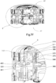
- Fig. 5D shows, in a sectional side view, in detail the arrangement of the motor and gear components within a cavity of the base body 70 (or within a cavity created by the base body 70 or by the slotted link element 110). Such an arrangement also favors a relatively flat design of the whole coupling.
- Fig. 5E shows a pair of coupling means 10 both exhibiting the components according to Fig. 5D , in a decoupled state (no radial engagement of blocking elements 50, 51 in radial recess 71).
- the respective outer ring 30 of both passive coupling means 10, 10 is retracted.
- the ring 60 exhibits a conical wedge-shaped geometry, which allows for actuating the Blocking elements 50, 51 for radial motion and for radially positioning the blocking elements 50, 51 within the radial cavity 71.
- This kind of radial form-fit blocking allows for interlocking of corresponding coupling means also in axial direction.
- the blocking elements 50, 51 may even autonomously search and find the designated end position (within recess 71; cf. Fig. 5H ), especially when provided in the shape of spheres/balls.
- the recess 71 may be provided in a shape facilitating this self-positioning mechanism, e.g. in the shape of a half-shell or a hollow sphere geometrically corresponding to the shape of the blocking elements 50, 51.
- Fig. 5E shows a situation A according to step S2, namely a state with the docking/coupling means are detached from each other.
- Fig. 5F shows a situation B according to step S3 in which the active coupling means deploys its engagement mechanism, both coupling components being axially retracted (axial springs are all preloaded).
- Fig. 5G shows a situation C according to step S4 in which the active coupling means deploys or has already deployed the engagement mechanism, the coupling components of the passive coupling means being (still) axially retracted. Active and passive state may be inverted also.
- Fig. 5H shows the components according to Fig. 5E , in fully coupled state (especially situation D).
- the respective outer ring 30 of both coupling means 10, 10 is positioned in an extended axial position.
- the respective passive element 10 can be forced for axial/radial engagement by the respective active element 10.
- front face of outer ring 30 is in contact with front face of corresponding outer ring 30.
- Fig. 5H shows a situation D according to step S5 in which the active coupling means forces the passive coupling means to deploy its engagement mechanism, both coupling components being axially extended (driven out).
- Blocking elements 50, 51 preferably are provided as balls/spheres, but may also be provided as pins, rolls or any rolling element.
- balls 50 are one example of a blocking element according to the invention.
- the Blocking elements 50, 51 can also be realized with modifications, especially by replacing a string of balls 50 by a pin 51.Such an implementation of pins 51 instead of balls 50 is described in Fig.5I , which can of course be combined with the other embodiments of the invention, especially by the replacement of one or more balls 50 by a pin 51.
- An active coupling means (active motor/actuator) mechanically couples by activating its own internal mechanism.
- the active coupling means By means of form-fit elements of the active coupling means, especially by axially arranged outer forcing pins 121 of the internal mechanism of the active coupling means, the internal mechanism of the corresponding (passive) coupling means can be activated.
- Decoupling may be initiated by relatively rotating the slotted link element 110 in opposite direction. Actuating motion is provided by internal relative rotational actuation of cam contours (resp. cam profiles) and/or guide slots extending on a cylindrical lateral area. Decoupling may be initiated both by active or passive coupling means, i.e., the process of decoupling may be independent of any previous coupling procedures.
- Actively or passively coupling may imply that the adapter ring 100 be actuated by internal and/or external forces, i.e. exclusively by the active internal coupling mechanism and/or by the coupling mechanism of the corresponding coupling means.
- the mechanism described above may also be implemented for electric coupling, as suggested in Fig. 7ff.
- each coupling means may exhibit further components for coupling not only forces or momentum, but also energy, data and/or fluids, wherein each corresponding component may be active or passive.
- outer ring 30 in Fig. 5ff. may be replaced by an alternative component or may even omitted, especially for simple connector applications.
- the profile 71 according to Fig. 5ff. may be duplicated in axial direction, on the lateral area of the base body 70. This may also allow for omitting elements 40.
- contour 11 may be provided in an interrupted configuration (open contour) or in a continuous configuration (closed contour).
- Fig. 6A , 6B , 6C , 6D , 6E show an androgynous coupling means according to a further one of the embodiments of the invention, wherein reference sign 16 signalizes an embodiment with power and data interface of a first type.
- reference signs not explicitly described in the following, it is referred to Fig. 5ff.
- Fig. 6A shows a base body 72 for a power and data interface of a first type, wherein a slotted link element 114, especially cam disc, is further provided with a (further, third) cam contour 115 (inner, closed).
- This configuration allows for relative axial positioning in two different manners, based on one single pivot actuation.
- the slotted link element 114 may provide for both electric and mechanic coupling.
- control PCB 250 control of coupling means
- second optical data interface 260 drive ring 270 (especially for electrical power transfer pins) with form fit elements 271, especially guide pins, electrical power distribution ring (top) 280 with contact rings 281, electrical power distribution ring (bottom) 290 with contact rings 291.
- the ring 270 may provide for fixation of any elements for energy and/or data and/or fluid transfer.
- the ring 270 may provide for synchronous connection of all contact elements fixed thereto.
- Guide pins 271 also allow for mechanical connection of inner push-push-mechanism or inner push-pull-mechanism.
- the ring 280 is made of copper (or another material with high electric conductivity) and allows for energy and data connections by means of pins 230. Rings 280,290 may be supported/bedded by force-loaded contact rings 281,291.
- Fig. 6B shows, in a perspective view onto the upper side resp. onto the front side, in detail the electrical power inlet (first pole) 300 and electrical power outlet (first pole) 301, as well as electrical power inlet (second pole) 302 and electrical power outlet (second pole) 303.
- Elements 300, 301,302, 303 allow for marking inlet or outlet openings at the front side of the respective coupling means, especially by an extended position or by an inserted position.
- Fig. 6D shows in detail in a sectional side view as well as in a detailed view a cross section 2 of a pair of corresponding coupling means 16, 16, in an interlocking state (coupled state, especially situation D), both axially and radially engaged.
- Fig. 6D illustrates electric connection by means of corresponding optocoupler elements 241 which are shown in contact with each other. Both outer rings are in the extended position (fully coupled). But, pins 230 for transfer of electrical power are not yet deployed.
- At least the following components are arranged within the cavity 75 defined by the base body or by the slotted link element of the respective coupling element: 200,210,220,230,240,241,250,270,271,280,290.
- Fig. 6E shows, in a perspective according to Fig. 6D , a state in which electrical pins are axially extended such that electrical connection is ensured.
- the pins 230 are now deployed.
- this coupling state especially situation E
- transfer of power and/or data can be carried out via optocoupler elements 241 contacting corresponding optocoupler elements 241.
- Fig. 7A further shows the power and data interface of a second type, namely an inner forcing ring 310 with form fit elements 311, 312 (sliding pins and forcing pins), an activation ring 320, preload springs 330, force-loading means 340 (preload springs), indexing ring 350, ring 360 with shutter elements and form fit elements 361 (especially guide slots), ring 370 with ring pedal 371 and form fit elements 372 (especially guide pins), force-loading means 380 (especially electrical preload springs), form fit elements 390 (especially guide pins), adapter ring 400 with form fit elements 401, 402, 403, especially interaction pins and sliding pins.
- the ring 360 shuts opening/cavity.
- Slots 361 provide a guiding contour for pins 372.
- the ring 370 supports pedals 371 for arranging contact elements for energy, data and fluids.
- Force-loading means 380 (especially preload spring) allow(s) for preload of element 370, especially in a direction towards the corresponding coupling means.
- Guiding pin 390 allows for guiding the element 380.
- the push-push-mechanism or push-pull-mechanism for predefining at least two axial relative positions may be implemented both for the mechanical coupling components as well as for the electrical coupling components (cf. reference signs 310, 320, 350, 360).
- relative rotation of slotted link elements allows for axial positioning for both: mechanical and electrical coupling.
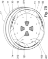
- Fig. 7B shows, in a perspective according to Fig. 5C , the central docking area of the coupling means, wherein openings 74 provide for contact areas 371 for transmitting power and/or data.
- the form fit elements (especially pins) 103, 121, 312, 401 are arranged in groups resp. in pairs 121, 312 and 103, 401 in radial distance to each other. This design allows for combining both functionalities (mechanical and electrical coupling) in a practical manner, especially also in a robust manner, and also on little installation space.
- Fig. 7C shows, in a perspective according to Fig. 5D , the central cavity defined by the respective coupling means, for arranging all electrical components within the same construction height.
- both internal coupling kinematics for mechanical and electrical coupling are arranged within an inner cavity of the ring-in-ring-arrangement.
- Fig. 7D shows in detail in a sectional side view as well as in a detailed view a cross section 3 of a pair of corresponding coupling means 17, 17, in an interlocking state (coupled state, especially situation D), both axially and radially engaged.
- Fig. 7D illustrates a fully engaged coupled state with both coupling means in fully coupled position. Both outer rings are in the extended position (fully coupled) and contact each other.
- the preload spring 380 is pre-stressed; there is not yet any electric contact between the corresponding coupling means.
- At least the following components are arranged within a cavity 75 defined by the base body or by the slotted link element of the respective coupling element: 310,311,312,320,330,340,350,360,361,370,371,372,380,390,400,401,402,403.
- Fig. 7E shows, in a perspective according to Fig. 7D , a state in which electric connection is not yet established.
- the preload spring 380 is extended, and shutter elements 60 are extended. There is still axial engagement by forcing pins (situation D, E).
- Fig. 7F shows, in a perspective according to Fig. 7D , a coupled state with electric connection providing for transfer of power and/or data.
- Corresponding electrical contacts 371 are in contact with each other. No forcing pin is in axial engagement any more.
- Fig. 7F illustrates a state after situation E. It can be seen that at least four three different assembly groups are arranged in radial sequence, namely the drive unit 130,140, further the components for electric connection (310,... ,403), further the internal push-push-mechanism or push-pull-mechanism (internal state machine), and further the relative positioning kinematics (especially with ring-in-ring-arrangement).
- Fig. 7ff. allows for a plurality of advantages, especially in view of a plurality of requirements.
- the embodiment shown in Fig. 7ff. provides for broad functionality.
- embodiments shown in Fig. 6ff. and Fig. 7ff. may be combined.
- embodiments shown in Fig. 6ff. may exhibit plates or discs or bushings instead of pins
- embodiments shown in Fig. 7ff. may exhibit pins instead of plates or discs or bushings.
- all electrical connections may vary in form and function.
- punctiform or 2D contacts may be varied (especially contact pins).
- Fig. 8 illustrates two vehicles 410 arranged in series, respectively exhibiting two androgynous coupling means 10 mounted in the front and at the stern (rear end). Each pair of androgynous coupling means 10 provides for an androgynous coupling which couples the vehicles. The process of coupling the vehicles or any other devices is illustrated in Fig. 9A, 9B .
- Fig. 9A, 9B, 9C , 9D, 9E, 9F illustrate two corresponding coupling means each being mounted on a cable, tube, spindle or axle 4, in a decoupled and in a coupled state.
- Fig. 9C , 9F show in detail (detailed cross sections 5, 6) the arrangement of the involved components (especially 30, 31, 50, 51, 60, 61, 62, 70) in a decoupled and in a coupled state, same as e.g. Fig. 5F , 5H .
- Fig. 9ff. illustrate the advantage of minor axial actuation and little axial installation space requirements of the inventive coupling kinematics.
- This embodiment especially refers to a configuration which is favorable for coupling of cables or lines for energy/fluids/data, of tubes, linkages, rods, or the like.
- Fig. 11A, 11B illustrate the use of the inventive coupling for coupling a robot 9.
- Corresponding coupling means are mounted on any arm of the robot 9 and on a free end of the robot, especially on a tool 9.1 like a mechanical hand or gripper.
- Fig. 12A, 12B , 12C, 12D illustrate a further embodiment for an androgynous coupling means, especially in an inverted arrangement, as compared to previous embodiments.
- this embodiment differs e.g. as far as the orientation of male coupling sections resp. of radial recesses is concerned: the radial recesses of the male coupling sections are oriented radially inwards (not outwards); the radial recesses are accessible radially inwards only.
- the lateral locking contour provides for axial and radial interlocking with blocking elements which are arranged inside of the male coupling sections (further inwards).
- the male coupling sections extend axially, but they are no oriented radially outwards.
- the male coupling sections are arranged within a ring cavity having a diameter (resp. width) smaller than the diameter (resp. width) of the base body. Nonetheless, there is no need for radial overlap, neither outwards (cf. Fig. 1 , 5A ) nor inwards. Rather, the radial recesses may be provided in axial prolongation of the respective coupling section. As can be seen in Fig. 12C, 12D , radial recesses are arranged within the axial prolongation of the ring geometry of the base body 70.
- This arrangement also favors a ring-in-ring-arrangement, i.e., an accommodation and axial guidance of rings within other rings, especially positioning ring within outer ring, and outer ring within base body, as already explained above in conjunction with Fig. 5ff.
- Fig. 12ff. especially illustrate a triple-ring-arrangement.
- the base body 70 provides for a ring cavity for accommodating the outer ring 30, and the outer ring 30 provides for a ring cavity for accommodating the positioning element 60.
- the outer ring 30 exhibits a radial land or protrusion for axially limiting the axial position of the blocking elements 50, 51.
- the outer ring's cross-section geometry may describe a "u”-letter with roof, or a kind of "G”-letter, or an "O”-letter opened at one corner. This allows for favorable relative arrangement and guidance of the involved kinematic elements.
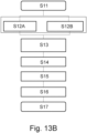
- FIG. 13A , 13B illustrate one of preferred embodiments of the inventive coupling and decoupling procedures in an exemplified explanatory manner.
- Fig. 13A illustrates steps S1, S2, S3, S4, S5, S6, S6A, S6B, S7 of a coupling procedure.
- Fig. 13B illustrates steps S11, S12, S12A, S12B, S13, S14, S15, S16, S17 of an undocking/decoupling procedure.
Landscapes
- Engineering & Computer Science (AREA)
- General Engineering & Computer Science (AREA)
- Remote Sensing (AREA)
- Aviation & Aerospace Engineering (AREA)
- Mechanical Engineering (AREA)
- Quick-Acting Or Multi-Walled Pipe Joints (AREA)
Claims (15)
- Moyen d'accouplement androgyne (10, 16, 17) présentant des sections d'accouplement mâle et femelle (11, 12), dans lequel le moyen d'accouplement androgyne est configuré pour un accouplement par ajustement de forme avec au moins un autre de ces moyens d'accouplement androgyne (10, 16, 17), présentant des sections d'accouplement mâle et femelle géométriquement respectives (11, 12) sur la base d'un emboîtement axial entre les sections d'accouplement mâle et femelle (11, 12), les sections d'accouplement mâle (11) présentant au moins un contour de verrouillage latéral configuré pour un ajustement de forme avec au moins un élément de blocage (50) sur la base d'un emboîtement radial, dans lequel le contour de verrouillage latéral respectif est orienté dans une direction radiale, en particulier dans une direction radiale vers l'extérieur, dans lequel, à l'intérieur du contour de verrouillage latéral respectif, les sections d'accouplement mâles présentent au moins un renfoncement radial (71) fournissant une cavité radiale pour arranger ou loger radialement, dans un état couplé, au moins un élément de blocage, en particulier au moins une bille, dans lequel, dans l'état couplé, l'évidement radial (71) est configuré pour fixer l'au moins un élément de blocage sur la base d'un ajustement de forme à l'intérieur de la cavité radiale, de sorte que le moyen de couplage androgyne est fixé dans une position relative axiale par rapport au moyen de couplage androgyne correspondant, caractérisé en ce que l'au moins un élément de blocage (50) est configuré pour être actionné dans la direction radiale sur la base de l'actionnement axial d'un élément de positionnement (60) engageant l'au moins un élément de blocage lorsqu'il est actionné dans la direction axiale, dans lequel l'évidement radial (71) est agencé de telle sorte que, sur la base d'un mouvement relatif axial d'au moins deux anneaux d'un agencement en anneau d'une pluralité d'anneaux à guidage axial, l'au moins un élément de blocage (50) peut être positionné radialement et fixé par un mouvement relatif axial de l'élément de positionnement (60) sous la forme d'un anneau de positionnement d'au moins deux anneaux, en particulier un anneau de positionnement avec une géométrie conique ou en coin, et dans lequel, en rétractant l'anneau de positionnement (60) dans la direction axiale, l'au moins un élément de blocage (50) peut être débloqué.
- Le moyen d'accouplement androgyne selon la revendication 1, dans lequel le moyen d'accouplement androgyne est configuré pour l'emboîtement diagonal des sections d'accouplement correspondantes, en particulier pour assurer ou améliorer une trajectoire d'accostage diagonale ; et/ou dans lequel le moyen d'accouplement androgyne présente des paires de sections d'accouplement (11, 12) disposées de manière opposée et configurées pour l'emboîtement diagonal d'un moyen d'accouplement androgyne correspondant.
- Le moyen d'accouplement androgyne (10, 16, 17) selon la revendication 1 ou 2, dans lequel le moyen d'accouplement androgyne présente une cavité intérieure configurée pour disposer au moins un composant assurant la connexion électrique avec le moyen d'accouplement correspondant, de préférence configuré pour positionner relativement au moins une broche de transfert de puissance et/ou de données disposée dans une direction axiale, la cavité intérieure étant disposée radialement vers l'intérieur par rapport à l'évidement radial.
- Dispositif, notamment modulaire (20), comprenant au moins un moyen d'accouplement androgyne (10, 16, 17) selon l'une quelconque des revendications précédentes, notamment dispositif en forme de cube modulaire avec au moins deux moyens d'accouplement androgyne disposés sur des côtés/surfaces différents du dispositif, notamment avec un moyen d'accouplement androgyne disposé sur chaque côté du dispositif, dans lequel le moyen d'accouplement androgyne est monté de manière fixe sur le dispositif, notamment au moyen d'un anneau extérieur (30) du moyen d'accouplement androgyne.
- Agencement d'un dispositif selon la revendication précédente, dans lequel le dispositif est prévu dans l'une des configurations suivantes : engrenage planétaire, prise de force (PTO), système de verrouillage, robot, véhicule, ensemble de véhicules, notamment camions ou remorques de camions, satellite ou ensemble de satellites, outil actif configuré pour être actionné activement, tuyaux, tiges de forage ou outils de forage, quadcoptère ou multicoptère, système logistique ou système de chargement ou de cargaison, aérodyne ou aéronef.
- Agencement d'un dispositif selon la revendication 4, dans lequel le dispositif est prévu dans la configuration d'un connecteur et est configuré pour connecter des lignes ou des flux d'énergie et/ou pour connecter des lignes ou des flux d'information et/ou pour connecter des lignes ou des flux de fluides comme des flux de gaz, notamment pour connecter thermiquement et/ou électriquement ces lignes ou ces flux.
- Accouplement androgyne comprenant au moins deux moyens d'accouplement androgyne (10, 16, 17) selon l'une des revendications 1 à 3, dans lequel l'accouplement androgyne est configuré pour l'accouplement par ajustement de forme dans les directions axiale et radiale, dans lequel l'accouplement androgyne présente une pluralité d'éléments de blocage (50), en particulier des sphères, et présente en outre au moins un élément de positionnement (60) configuré pour positionner les éléments de blocage de leur moyen d'accouplement androgyne respectif de manière à ce que le moyen d'accouplement androgyne soit positionné de manière fixe dans une position relative axiale par rapport au moyen d'accouplement androgyne correspondant.
- Procédé d'accouplement réversible d'au moins deux appareils (20), notamment modulaires, au moyen d'un accouplement androgyne comprenant au moins deux moyens d'accouplement androgyne (10, 16, 17), notamment au moyen d'un accouplement androgyne selon la revendication 7, au moins un moyen d'accouplement androgyne étant disposé de manière fixe sur chaque appareil, dans lequel l'accouplement des au moins deux moyens d'accouplement androgyne est réalisé de manière ajustée sur la base d'un emboîtement axial au moyen de sections d'accouplement mâle et femelle (11,12) sur chacun des deux moyens d'accouplement androgynes correspondants, dans lequel les sections d'accouplement mâles et femelles se chevauchent dans une direction axiale, dans lequel la fixation de la position axiale relative des moyens d'accouplement androgynes correspondants à l'état accouplé est effectuée d'une manière adaptée à la forme sur la base d'un emboîtement radial au moyen des sections d'accouplement mâles (11) des moyens d'accouplement androgynes respectifs, dans lequel au moins un élément de blocage (50) est actionné dans la direction radiale, par un actionnement axial d'un élément de positionnement (60) engageant le au moins un élément de blocage lorsqu'il est actionné dans la direction axiale, pour engager radialement le contour de verrouillage latéral des sections d'accouplement mâles d'au moins un des moyens d'accouplement androgynes et pour bloquer axialement le moyen d'accouplement androgyne respectif sur la base de cet engagement radial, dans lequel, pour l'accouplement, un anneau extérieur (30) est rétracté, de sorte que l'ajustement de forme est libéré, permettant l'emboîtement diagonal d'un autre moyen d'accouplement, en actionnant l'élément de positionnement sous la forme d'un anneau intérieur (60) avec, de préférence, une géométrie ou un profil en forme de coin, pour débloquer l'au moins un élément de blocage (50).
- Procédé selon la revendication précédente, dans lequel, à l'état couplé, la position d'au moins un élément de blocage est fixée de manière ajustée dans une cavité du contour de verrouillage latéral, de sorte que le dispositif (20) est couplé de manière autobloquante et que le moyen de couplage androgyne est positionné de manière fixe dans une position relative axiale par rapport au moyen de couplage androgyne correspondant.
- Procédé selon l'une quelconque des revendications précédentes, dans lequel, pour le désaccouplement, un anneau d'indexation (90) et un anneau d'activation (80) sont déplacés axialement et positionnés l'un par rapport à l'autre, en particulier de manière à ce qu'un élément de fixation respectif (61) s'engage/désengage d'un contour d'au moins un des anneaux, en particulier d'un profil en dents de scie de l'anneau d'indexation (90), ce qui induit une rotation relative des anneaux, en particulier à l'intérieur d'une cavité du moyen d'accouplement androgyne respectif.
- Méthode selon l'une quelconque des revendications précédentes, dans laquelle le couplage avec au moins un dispositif (20) est effectué par au moins l'une des formes d'actionnement suivantes : actionnement hydraulique, actionnement mécanique, actionnement pneumatique, actionnement électrique, actionnement magnétique, actionnement électromagnétique, actionnement piézoélectrique.
- Utilisation d'un accouplement androgyne selon la revendication 7 ou d'un moyen d'accouplement androgyne (10, 16, 17) selon l'une quelconque des revendications 1 à 3, pour/dans un engrenage planétaire, notamment pour actionner un disque à cames, notamment en liaison avec au moins un capteur d'angle, ou pour/dans un mécanisme de poussée-poussée à ressort, ou pour/dans un mécanisme de stylo à bille, ou pour/dans un accouplement hydraulique, ou pour/dans un accouplement mécanique, ou pour/dans un accouplement pneumatique, notamment pour un accouplement pneumatique à dégagement rapide, ou pour un accouplement électrique ou pour la transmission de données, ou pour un système de verrouillage, notamment pour un système de verrouillage pour l'usinage industriel, ou pour un robot, ou comme changeur d'outils robotisé, ou pour un véhicule, ou pour un satellite, ou pour un outil, notamment dans un outil actif configuré pour être actionné activement, ou pour le couplage de tubes de forage ou de tiges de forage ou d'outils d'alésage.
- Utilisation d'un accouplement androgyne selon la revendication 7 ou de moyens d'accouplement androgyne (10, 16, 17) selon l'une des revendications 1 à 3, pour/dans un engin spatial ou un satellite, en particulier pour accoupler au moins deux composants du groupe de composants suivant : au moins deux satellites, ou un dispositif quelconque et une station spatiale, au moins deux dispositifs aérospatiaux, en particulier dans l'espace extra-atmosphérique ou en route vers l'espace extra-atmosphérique, ou une pluralité de composants pour monter/construire une unité opérationnelle pour des applications extraterrestres.
- Utilisation d'un attelage androgyne selon la revendication 7 ou de moyens d'attelage androgyne (10, 16, 17) selon l'une quelconque des revendications 1 à 3, pour/dans un drone ou pour/dans un quadcoptère ou multicoptère, notamment pour l'attelage d'au moins un élément du groupe d'éléments suivants : au moins une charge/cargo, au moins un colis, au moins un autre aérodyne ou aéronef.
- Utilisation d'un attelage androgyne selon la revendication 7 ou de moyens d'attelage androgyne (10, 16, 17) selon l'une quelconque des revendications 1 à 3, pour/dans des véhicules, notamment pour/dans un camion ou pour/dans des remorques de camion, notamment pour accoupler au moins deux composants du groupe de composants suivant : au moins deux véhicules, notamment en série l'un après l'autre, au moins deux remorques de camion, notamment en série l'une après l'autre.
Applications Claiming Priority (2)
| Application Number | Priority Date | Filing Date | Title |
|---|---|---|---|
| EP19161610.1A EP3705409A1 (fr) | 2019-03-08 | 2019-03-08 | Dispositif et procédé de couplage androgyne et utilisation associée |
| PCT/EP2020/056089 WO2020182682A1 (fr) | 2019-03-08 | 2020-03-06 | Dispositif et procédé de couplage androgyne ainsi que son utilisation |
Publications (3)
| Publication Number | Publication Date |
|---|---|
| EP3934983A1 EP3934983A1 (fr) | 2022-01-12 |
| EP3934983B1 true EP3934983B1 (fr) | 2023-10-25 |
| EP3934983C0 EP3934983C0 (fr) | 2023-10-25 |
Family
ID=65729213
Family Applications (2)
| Application Number | Title | Priority Date | Filing Date |
|---|---|---|---|
| EP19161610.1A Withdrawn EP3705409A1 (fr) | 2019-03-08 | 2019-03-08 | Dispositif et procédé de couplage androgyne et utilisation associée |
| EP20725411.1A Active EP3934983B1 (fr) | 2019-03-08 | 2020-03-06 | Dispositif et procédé de couplage androgyne et utilisation associée |
Family Applications Before (1)
| Application Number | Title | Priority Date | Filing Date |
|---|---|---|---|
| EP19161610.1A Withdrawn EP3705409A1 (fr) | 2019-03-08 | 2019-03-08 | Dispositif et procédé de couplage androgyne et utilisation associée |
Country Status (4)
| Country | Link |
|---|---|
| US (1) | US12104633B2 (fr) |
| EP (2) | EP3705409A1 (fr) |
| JP (1) | JP7417620B2 (fr) |
| WO (1) | WO2020182682A1 (fr) |
Families Citing this family (7)
| Publication number | Priority date | Publication date | Assignee | Title |
|---|---|---|---|---|
| CN112208803B (zh) * | 2020-09-30 | 2021-11-30 | 哈尔滨工业大学 | 一种可实现多星顺序释放的锁紧分离机构及其工作方法 |
| CN113488811B (zh) * | 2021-06-25 | 2022-03-29 | 中航光电科技股份有限公司 | 一种自耦合全中性对接装置及连接器 |
| CN115972139B (zh) * | 2023-01-05 | 2023-08-15 | 哈尔滨工业大学 | 一种主被动端同构式大容差对接装置 |
| CN116513496B (zh) * | 2023-05-10 | 2024-01-30 | 重庆开拓卫星科技有限公司 | 一种驱动备份的太阳翼驱动装置 |
| EP4530145A1 (fr) | 2023-09-29 | 2025-04-02 | Ceilix AG | Système automatique pour le transport de cabines de transport, système logistique et procédé de manipulation d'une pluralité de cabines |
| EP4530244A1 (fr) | 2023-09-29 | 2025-04-02 | Ceilix AG | Dispositif de suspension de plafond pour lever, transférer et abaisser des conteneurs, procédé de fonctionnement du dispositif de suspension de plafond |
| EP4714834A1 (fr) * | 2024-09-20 | 2026-03-25 | EXOLAUNCH GmbH | Dispositif pour attacher une charge utile sur un véhicule spatial |
Family Cites Families (27)
| Publication number | Priority date | Publication date | Assignee | Title |
|---|---|---|---|---|
| US2553220A (en) * | 1948-05-25 | 1951-05-15 | Bendix Aviat Corp | Quick detachable means |
| US3342510A (en) * | 1964-09-22 | 1967-09-19 | Walters Tom | Coupling |
| FR2248460B1 (fr) * | 1973-10-19 | 1980-12-05 | Deutsch Co | |
| US5301985A (en) * | 1993-03-05 | 1994-04-12 | Angus Fire Armour Corp. | Double point supported locking lever for a hose coupling assembly |
| US5658159A (en) * | 1995-10-27 | 1997-08-19 | Biw Connector Systems, Inc. | Connector system and methods |
| KR100363877B1 (ko) * | 1997-10-16 | 2002-12-11 | 사꾸라고무가부시기가이샤 | 관부재 이음장치 및 그 제조방법 |
| US6354540B1 (en) | 1998-09-29 | 2002-03-12 | The United States Of America As Represented By The Administrator Of The National Aeronautics And Space Administration | Androgynous, reconfigurable closed loop feedback controlled low impact docking system with load sensing electromagnetic capture ring |
| JP2002048283A (ja) | 2000-08-01 | 2002-02-15 | Sakura Gomme Kk | 結合金具 |
| DE10058520C1 (de) * | 2000-11-24 | 2002-07-04 | Itw Automotive Prod Gmbh & Co | Vorrichtung zum Befestigen eines scheibenförmigen Bauteils in einer Aufnahme |
| JP5064622B2 (ja) * | 2001-09-21 | 2012-10-31 | パスカルエンジニアリング株式会社 | クランプ装置 |
| CA2478532C (fr) | 2002-03-05 | 2009-12-22 | Sakura Rubber Co., Ltd. | Dispositif de connexion equipe d'une structure evitant le desserrage |
| US7395584B2 (en) * | 2006-01-27 | 2008-07-08 | Universal Trim Supply Co., Ltd. | Hermaphroditic connector |
| US7543779B1 (en) * | 2007-01-19 | 2009-06-09 | The United States Of America As Represented By The Administrator Of The National Aeronautics And Space Administration | Low-impact mating system |
| JP4234777B1 (ja) * | 2008-05-30 | 2009-03-04 | 浩平 中村 | 接続構造 |
| DE102010005895A1 (de) * | 2010-01-27 | 2011-07-28 | projekt management hackenfort GmbH, 48739 | Verbinder und Bolzen zum lösbaren Verbinden von insbesondere Behältern |
| US20140096467A1 (en) * | 2011-05-31 | 2014-04-10 | 3Form, Inc. | Magnetic-lock panel mounting apparatus, systems and methods |
| DE102014104695A1 (de) * | 2014-04-02 | 2015-10-08 | Rheinisch-Westfälische Technische Hochschule (Rwth) Aachen | Androgyne Kopplungseinrichtung zur Verbindung von Modulen sowie entsprechende Module |
| CN108431340A (zh) * | 2015-12-04 | 2018-08-21 | 保力集团有限责任公司 | 用于连接结构部件的联接器、设置有该联接器的桁架、相关方法和用途 |
| CN205370102U (zh) * | 2015-12-10 | 2016-07-06 | 路华(厦门)贸易有限公司 | 一种帐篷支撑架及具有该帐篷支撑架的帐篷 |
| DE202016102290U1 (de) * | 2016-04-29 | 2016-05-17 | Entron Design Ltd | Seitlich drückbare Einrast- und Verriegelungsvorrichtung |
| AR104757A1 (es) * | 2016-05-27 | 2017-08-09 | Univ Nac De Quilmes (Unq) | Adaptador universal para fichas de audio |
| KR101887538B1 (ko) * | 2016-06-23 | 2018-08-10 | 한국과학기술연구원 | 무성별 결합이 가능한 모듈 연결장치 |
| JP6863582B2 (ja) | 2017-07-10 | 2021-04-21 | パスカルエンジニアリング株式会社 | ロボットアームカップリング装置 |
| DE102017118251A1 (de) * | 2017-08-10 | 2019-02-14 | Airbus Operations Gmbh | Kopplungselement und Kopplungssystem sowie Verfahren zum Koppeln von zwei Modulen und Luftfahrzeug |
| KR102527659B1 (ko) * | 2017-11-27 | 2023-05-03 | 삼성전자주식회사 | 공기청정기 |
| CN108275289B (zh) * | 2017-12-14 | 2020-05-08 | 北京卫星制造厂 | 一种可重复连接分离装置及模块化航天器的紧固分离装置 |
| EP3825237A1 (fr) * | 2019-11-25 | 2021-05-26 | Space Applications Services NV/SA | Dispositif et procédé pour une fonction de couplage mâle et femelle redondante ainsi qu'utilisation |
-
2019
- 2019-03-08 EP EP19161610.1A patent/EP3705409A1/fr not_active Withdrawn
-
2020
- 2020-03-06 JP JP2021553326A patent/JP7417620B2/ja active Active
- 2020-03-06 EP EP20725411.1A patent/EP3934983B1/fr active Active
- 2020-03-06 WO PCT/EP2020/056089 patent/WO2020182682A1/fr not_active Ceased
- 2020-03-06 US US17/437,224 patent/US12104633B2/en active Active
Also Published As
| Publication number | Publication date |
|---|---|
| WO2020182682A1 (fr) | 2020-09-17 |
| US20220170498A1 (en) | 2022-06-02 |
| US12104633B2 (en) | 2024-10-01 |
| CA3132561A1 (fr) | 2020-09-17 |
| EP3705409A1 (fr) | 2020-09-09 |
| EP3934983A1 (fr) | 2022-01-12 |
| JP2022540969A (ja) | 2022-09-21 |
| EP3934983C0 (fr) | 2023-10-25 |
| JP7417620B2 (ja) | 2024-01-18 |
Similar Documents
| Publication | Publication Date | Title |
|---|---|---|
| EP3934983B1 (fr) | Dispositif et procédé de couplage androgyne et utilisation associée | |
| EP3825237A1 (fr) | Dispositif et procédé pour une fonction de couplage mâle et femelle redondante ainsi qu'utilisation | |
| WO2020182692A2 (fr) | Dispositif et procédé d'accouplement androgyne ainsi que son utilisation | |
| CN102490181B (zh) | 用于空间在轨模块更换的抓持机构 | |
| EP3854536B1 (fr) | Outil multifonctionnel d'entretien robotique | |
| EP3175511B1 (fr) | Connecteur d'amarrage d'engin spatial | |
| US8209840B2 (en) | Rotating coupling for robotic tool changer | |
| US8550192B2 (en) | Payload module for mobility assist | |
| US7543779B1 (en) | Low-impact mating system | |
| US11643226B1 (en) | Spacecraft mating mechanisms | |
| EP4219319B1 (fr) | Outil de ravitaillement en carburant et système incorporant l'outil de ravitaillement en carburant en carburant | |
| US20250083313A1 (en) | Robotic systems, methods, and devices for grappling and actuating a payload | |
| EP0405476A1 (fr) | Module d'un joint universel | |
| US20130305867A1 (en) | Tension Stiffened and Tendon Actuated Manipulator and a Hinge for Use Therein | |
| CA3123270A1 (fr) | Systeme d'interface a verrouillage radial | |
| CA3132561C (fr) | Dispositif et procede de couplage androgyne ainsi que son utilisation | |
| US5219318A (en) | Spline screw autochanger | |
| US5244406A (en) | Spline screw payload fastening system | |
| WO2021225702A1 (fr) | Ensembles de capture de véhicule et dispositifs, systèmes et procédés associés | |
| US12242180B1 (en) | Tool drive system | |
| CN117302566A (zh) | 一种捕获对接机构及对接方法 | |
| Yaskevich | Docking systems design | |
| Lambooy et al. | Some mechanical design aspects of the European Robotic Arm | |
| Howard | Design of a robotic wrist and tool-exchange mechanism for satellite servicing | |
| JP2025092469A (ja) | スケーラブルなロボット的に適合可能なペイロードロジスティクスインターフェースのためのシステムおよび方法 |
Legal Events
| Date | Code | Title | Description |
|---|---|---|---|
| STAA | Information on the status of an ep patent application or granted ep patent |
Free format text: STATUS: UNKNOWN |
|
| STAA | Information on the status of an ep patent application or granted ep patent |
Free format text: STATUS: THE INTERNATIONAL PUBLICATION HAS BEEN MADE |
|
| PUAI | Public reference made under article 153(3) epc to a published international application that has entered the european phase |
Free format text: ORIGINAL CODE: 0009012 |
|
| STAA | Information on the status of an ep patent application or granted ep patent |
Free format text: STATUS: REQUEST FOR EXAMINATION WAS MADE |
|
| 17P | Request for examination filed |
Effective date: 20211006 |
|
| AK | Designated contracting states |
Kind code of ref document: A1 Designated state(s): AL AT BE BG CH CY CZ DE DK EE ES FI FR GB GR HR HU IE IS IT LI LT LU LV MC MK MT NL NO PL PT RO RS SE SI SK SM TR |
|
| DAV | Request for validation of the european patent (deleted) | ||
| DAX | Request for extension of the european patent (deleted) | ||
| GRAP | Despatch of communication of intention to grant a patent |
Free format text: ORIGINAL CODE: EPIDOSNIGR1 |
|
| STAA | Information on the status of an ep patent application or granted ep patent |
Free format text: STATUS: GRANT OF PATENT IS INTENDED |
|
| INTG | Intention to grant announced |
Effective date: 20230503 |
|
| GRAS | Grant fee paid |
Free format text: ORIGINAL CODE: EPIDOSNIGR3 |
|
| GRAA | (expected) grant |
Free format text: ORIGINAL CODE: 0009210 |
|
| STAA | Information on the status of an ep patent application or granted ep patent |
Free format text: STATUS: THE PATENT HAS BEEN GRANTED |
|
| AK | Designated contracting states |
Kind code of ref document: B1 Designated state(s): AL AT BE BG CH CY CZ DE DK EE ES FI FR GB GR HR HU IE IS IT LI LT LU LV MC MK MT NL NO PL PT RO RS SE SI SK SM TR |
|
| REG | Reference to a national code |
Ref country code: GB Ref legal event code: FG4D |
|
| REG | Reference to a national code |
Ref country code: CH Ref legal event code: EP |
|
| REG | Reference to a national code |
Ref country code: DE Ref legal event code: R096 Ref document number: 602020019826 Country of ref document: DE |
|
| REG | Reference to a national code |
Ref country code: IE Ref legal event code: FG4D |
|
| U01 | Request for unitary effect filed |
Effective date: 20231117 |
|
| U07 | Unitary effect registered |
Designated state(s): AT BE BG DE DK EE FI FR IT LT LU LV MT NL PT SE SI Effective date: 20231123 |
|
| PG25 | Lapsed in a contracting state [announced via postgrant information from national office to epo] |
Ref country code: GR Free format text: LAPSE BECAUSE OF FAILURE TO SUBMIT A TRANSLATION OF THE DESCRIPTION OR TO PAY THE FEE WITHIN THE PRESCRIBED TIME-LIMIT Effective date: 20240126 |
|
| PG25 | Lapsed in a contracting state [announced via postgrant information from national office to epo] |
Ref country code: IS Free format text: LAPSE BECAUSE OF FAILURE TO SUBMIT A TRANSLATION OF THE DESCRIPTION OR TO PAY THE FEE WITHIN THE PRESCRIBED TIME-LIMIT Effective date: 20240225 |
|
| PG25 | Lapsed in a contracting state [announced via postgrant information from national office to epo] |
Ref country code: ES Free format text: LAPSE BECAUSE OF FAILURE TO SUBMIT A TRANSLATION OF THE DESCRIPTION OR TO PAY THE FEE WITHIN THE PRESCRIBED TIME-LIMIT Effective date: 20231025 |
|
| PG25 | Lapsed in a contracting state [announced via postgrant information from national office to epo] |
Ref country code: IS Free format text: LAPSE BECAUSE OF FAILURE TO SUBMIT A TRANSLATION OF THE DESCRIPTION OR TO PAY THE FEE WITHIN THE PRESCRIBED TIME-LIMIT Effective date: 20240225 Ref country code: GR Free format text: LAPSE BECAUSE OF FAILURE TO SUBMIT A TRANSLATION OF THE DESCRIPTION OR TO PAY THE FEE WITHIN THE PRESCRIBED TIME-LIMIT Effective date: 20240126 Ref country code: ES Free format text: LAPSE BECAUSE OF FAILURE TO SUBMIT A TRANSLATION OF THE DESCRIPTION OR TO PAY THE FEE WITHIN THE PRESCRIBED TIME-LIMIT Effective date: 20231025 |
|
| U20 | Renewal fee for the european patent with unitary effect paid |
Year of fee payment: 5 Effective date: 20240326 |
|
| PG25 | Lapsed in a contracting state [announced via postgrant information from national office to epo] |
Ref country code: RS Free format text: LAPSE BECAUSE OF FAILURE TO SUBMIT A TRANSLATION OF THE DESCRIPTION OR TO PAY THE FEE WITHIN THE PRESCRIBED TIME-LIMIT Effective date: 20231025 Ref country code: PL Free format text: LAPSE BECAUSE OF FAILURE TO SUBMIT A TRANSLATION OF THE DESCRIPTION OR TO PAY THE FEE WITHIN THE PRESCRIBED TIME-LIMIT Effective date: 20231025 Ref country code: NO Free format text: LAPSE BECAUSE OF FAILURE TO SUBMIT A TRANSLATION OF THE DESCRIPTION OR TO PAY THE FEE WITHIN THE PRESCRIBED TIME-LIMIT Effective date: 20240125 Ref country code: HR Free format text: LAPSE BECAUSE OF FAILURE TO SUBMIT A TRANSLATION OF THE DESCRIPTION OR TO PAY THE FEE WITHIN THE PRESCRIBED TIME-LIMIT Effective date: 20231025 |
|
| PG25 | Lapsed in a contracting state [announced via postgrant information from national office to epo] |
Ref country code: CZ Free format text: LAPSE BECAUSE OF FAILURE TO SUBMIT A TRANSLATION OF THE DESCRIPTION OR TO PAY THE FEE WITHIN THE PRESCRIBED TIME-LIMIT Effective date: 20231025 |
|
| REG | Reference to a national code |
Ref country code: DE Ref legal event code: R097 Ref document number: 602020019826 Country of ref document: DE |
|
| PG25 | Lapsed in a contracting state [announced via postgrant information from national office to epo] |
Ref country code: SK Free format text: LAPSE BECAUSE OF FAILURE TO SUBMIT A TRANSLATION OF THE DESCRIPTION OR TO PAY THE FEE WITHIN THE PRESCRIBED TIME-LIMIT Effective date: 20231025 |
|
| PG25 | Lapsed in a contracting state [announced via postgrant information from national office to epo] |
Ref country code: SM Free format text: LAPSE BECAUSE OF FAILURE TO SUBMIT A TRANSLATION OF THE DESCRIPTION OR TO PAY THE FEE WITHIN THE PRESCRIBED TIME-LIMIT Effective date: 20231025 Ref country code: SK Free format text: LAPSE BECAUSE OF FAILURE TO SUBMIT A TRANSLATION OF THE DESCRIPTION OR TO PAY THE FEE WITHIN THE PRESCRIBED TIME-LIMIT Effective date: 20231025 Ref country code: RO Free format text: LAPSE BECAUSE OF FAILURE TO SUBMIT A TRANSLATION OF THE DESCRIPTION OR TO PAY THE FEE WITHIN THE PRESCRIBED TIME-LIMIT Effective date: 20231025 Ref country code: CZ Free format text: LAPSE BECAUSE OF FAILURE TO SUBMIT A TRANSLATION OF THE DESCRIPTION OR TO PAY THE FEE WITHIN THE PRESCRIBED TIME-LIMIT Effective date: 20231025 |
|
| PLBE | No opposition filed within time limit |
Free format text: ORIGINAL CODE: 0009261 |
|
| STAA | Information on the status of an ep patent application or granted ep patent |
Free format text: STATUS: NO OPPOSITION FILED WITHIN TIME LIMIT |
|
| 26N | No opposition filed |
Effective date: 20240726 |
|
| REG | Reference to a national code |
Ref country code: CH Ref legal event code: PL |
|
| PG25 | Lapsed in a contracting state [announced via postgrant information from national office to epo] |
Ref country code: MC Free format text: LAPSE BECAUSE OF FAILURE TO SUBMIT A TRANSLATION OF THE DESCRIPTION OR TO PAY THE FEE WITHIN THE PRESCRIBED TIME-LIMIT Effective date: 20231025 |
|
| GBPC | Gb: european patent ceased through non-payment of renewal fee |
Effective date: 20240306 |
|
| PG25 | Lapsed in a contracting state [announced via postgrant information from national office to epo] |
Ref country code: MC Free format text: LAPSE BECAUSE OF FAILURE TO SUBMIT A TRANSLATION OF THE DESCRIPTION OR TO PAY THE FEE WITHIN THE PRESCRIBED TIME-LIMIT Effective date: 20231025 |
|
| PG25 | Lapsed in a contracting state [announced via postgrant information from national office to epo] |
Ref country code: GB Free format text: LAPSE BECAUSE OF NON-PAYMENT OF DUE FEES Effective date: 20240306 |
|
| PG25 | Lapsed in a contracting state [announced via postgrant information from national office to epo] |
Ref country code: IE Free format text: LAPSE BECAUSE OF NON-PAYMENT OF DUE FEES Effective date: 20240306 |
|
| PG25 | Lapsed in a contracting state [announced via postgrant information from national office to epo] |
Ref country code: IE Free format text: LAPSE BECAUSE OF NON-PAYMENT OF DUE FEES Effective date: 20240306 Ref country code: GB Free format text: LAPSE BECAUSE OF NON-PAYMENT OF DUE FEES Effective date: 20240306 Ref country code: CH Free format text: LAPSE BECAUSE OF NON-PAYMENT OF DUE FEES Effective date: 20240331 |
|
| U20 | Renewal fee for the european patent with unitary effect paid |
Year of fee payment: 6 Effective date: 20250327 |
|
| PG25 | Lapsed in a contracting state [announced via postgrant information from national office to epo] |
Ref country code: CY Free format text: LAPSE BECAUSE OF FAILURE TO SUBMIT A TRANSLATION OF THE DESCRIPTION OR TO PAY THE FEE WITHIN THE PRESCRIBED TIME-LIMIT; INVALID AB INITIO Effective date: 20200306 |
|
| PG25 | Lapsed in a contracting state [announced via postgrant information from national office to epo] |
Ref country code: HU Free format text: LAPSE BECAUSE OF FAILURE TO SUBMIT A TRANSLATION OF THE DESCRIPTION OR TO PAY THE FEE WITHIN THE PRESCRIBED TIME-LIMIT; INVALID AB INITIO Effective date: 20200306 |
|
| PG25 | Lapsed in a contracting state [announced via postgrant information from national office to epo] |
Ref country code: TR Free format text: LAPSE BECAUSE OF FAILURE TO SUBMIT A TRANSLATION OF THE DESCRIPTION OR TO PAY THE FEE WITHIN THE PRESCRIBED TIME-LIMIT Effective date: 20231025 |
|
| U20 | Renewal fee for the european patent with unitary effect paid |
Year of fee payment: 7 Effective date: 20260326 |