EP3935261B1 - Régulateur de débit de fond de trou - Google Patents
Régulateur de débit de fond de trou Download PDFInfo
- Publication number
- EP3935261B1 EP3935261B1 EP20769775.6A EP20769775A EP3935261B1 EP 3935261 B1 EP3935261 B1 EP 3935261B1 EP 20769775 A EP20769775 A EP 20769775A EP 3935261 B1 EP3935261 B1 EP 3935261B1
- Authority
- EP
- European Patent Office
- Prior art keywords
- filter medium
- flow
- counterpart
- defining
- shroud
- Prior art date
- Legal status (The legal status is an assumption and is not a legal conclusion. Google has not performed a legal analysis and makes no representation as to the accuracy of the status listed.)
- Active
Links
Images














Classifications
-
- E—FIXED CONSTRUCTIONS
- E21—EARTH OR ROCK DRILLING; MINING
- E21B—EARTH OR ROCK DRILLING; OBTAINING OIL, GAS, WATER, SOLUBLE OR MELTABLE MATERIALS OR A SLURRY OF MINERALS FROM WELLS
- E21B34/00—Valve arrangements for boreholes or wells
- E21B34/06—Valve arrangements for boreholes or wells in wells
- E21B34/14—Valve arrangements for boreholes or wells in wells operated by movement of tools, e.g. sleeve valves operated by pistons or wire line tools
-
- E—FIXED CONSTRUCTIONS
- E21—EARTH OR ROCK DRILLING; MINING
- E21B—EARTH OR ROCK DRILLING; OBTAINING OIL, GAS, WATER, SOLUBLE OR MELTABLE MATERIALS OR A SLURRY OF MINERALS FROM WELLS
- E21B34/00—Valve arrangements for boreholes or wells
- E21B34/06—Valve arrangements for boreholes or wells in wells
- E21B34/063—Valve or closure with destructible element, e.g. frangible disc
-
- E—FIXED CONSTRUCTIONS
- E21—EARTH OR ROCK DRILLING; MINING
- E21B—EARTH OR ROCK DRILLING; OBTAINING OIL, GAS, WATER, SOLUBLE OR MELTABLE MATERIALS OR A SLURRY OF MINERALS FROM WELLS
- E21B43/00—Methods or apparatus for obtaining oil, gas, water, soluble or meltable materials or a slurry of minerals from wells
-
- E—FIXED CONSTRUCTIONS
- E21—EARTH OR ROCK DRILLING; MINING
- E21B—EARTH OR ROCK DRILLING; OBTAINING OIL, GAS, WATER, SOLUBLE OR MELTABLE MATERIALS OR A SLURRY OF MINERALS FROM WELLS
- E21B43/00—Methods or apparatus for obtaining oil, gas, water, soluble or meltable materials or a slurry of minerals from wells
- E21B43/02—Subsoil filtering
- E21B43/08—Screens or liners
-
- E—FIXED CONSTRUCTIONS
- E21—EARTH OR ROCK DRILLING; MINING
- E21B—EARTH OR ROCK DRILLING; OBTAINING OIL, GAS, WATER, SOLUBLE OR MELTABLE MATERIALS OR A SLURRY OF MINERALS FROM WELLS
- E21B43/00—Methods or apparatus for obtaining oil, gas, water, soluble or meltable materials or a slurry of minerals from wells
- E21B43/02—Subsoil filtering
- E21B43/10—Setting of casings, screens, liners or the like in wells
- E21B43/103—Setting of casings, screens, liners or the like in wells of expandable casings, screens, liners, or the like
-
- E—FIXED CONSTRUCTIONS
- E21—EARTH OR ROCK DRILLING; MINING
- E21B—EARTH OR ROCK DRILLING; OBTAINING OIL, GAS, WATER, SOLUBLE OR MELTABLE MATERIALS OR A SLURRY OF MINERALS FROM WELLS
- E21B43/00—Methods or apparatus for obtaining oil, gas, water, soluble or meltable materials or a slurry of minerals from wells
- E21B43/34—Arrangements for separating materials produced by the well
- E21B43/38—Arrangements for separating materials produced by the well in the well
-
- E—FIXED CONSTRUCTIONS
- E21—EARTH OR ROCK DRILLING; MINING
- E21B—EARTH OR ROCK DRILLING; OBTAINING OIL, GAS, WATER, SOLUBLE OR MELTABLE MATERIALS OR A SLURRY OF MINERALS FROM WELLS
- E21B2200/00—Special features related to earth drilling for obtaining oil, gas or water
- E21B2200/06—Sleeve valves
-
- E—FIXED CONSTRUCTIONS
- E21—EARTH OR ROCK DRILLING; MINING
- E21B—EARTH OR ROCK DRILLING; OBTAINING OIL, GAS, WATER, SOLUBLE OR MELTABLE MATERIALS OR A SLURRY OF MINERALS FROM WELLS
- E21B2200/00—Special features related to earth drilling for obtaining oil, gas or water
- E21B2200/08—Down-hole devices using materials which decompose under well-bore conditions
Definitions
- the present disclosure relates to an apparatus for producing hydrocarbon material from a subterranean formation.
- Production wells may be drilled into oil-bearing zones of a subterranean formation to produce hydrocarbon material.
- a production system such as one having a port and a sleeve that opens and closes the port, may be used to stimulate the subterranean formation, and to produce the hydrocarbon material.
- the production system may inject stimulant into the subterranean formation via the port, and produce hydrocarbon material from the stimulated subterranean formation via the same port.
- a screen may be positioned over the port to filter materials from entering the production well.
- the sleeve may include the screen, such that the sleeve may be displaced to position the screen over the port.
- a flow control apparatus 200 for producing hydrocarbon material from a subterranean formation 100 is disclosed.
- the flow control apparatus 200 includes a housing 202.
- the housing 202 defines a fluid passage 224.
- a flow communicator 210 (such as, for example, in the form of one or more ports) extends through the housing 202 for effecting flow communication between the fluid passage 224 and the subterranean formation 100.
- the flow control apparatus 200 further includes a flow controller 250 disposed within the housing 202.
- the flow controller 250 is configured for modulating flow communication, between the housing passage 224 and the subterranean formation 100, which is effectible via the flow communicator 210.
- the flow controller 250 includes a filter medium 302.
- a filter medium-defining part 251 includes a filter medium 302.
- the filter medium 302 functions to prevent passage of oversize solid particulate matter from a first side of the filter medium-defining counterpart 300 to a second opposite side of the filter medium-defining counterpart 300.
- the filter medium 302 functions to prevent passage of oversize solid particulate matter from the subterranean formation 100 and into the housing passage 224 via the flow communicator 210.
- the oversize solid particulate matter, whose passage is prevented is +100 mesh proppant. This is to mitigate plugging of the flow control apparatus 200 or the wellbore 102 during production of hydrocarbon materials.
- the filter medium-defining part 251 functions as a debris retention device.
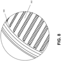
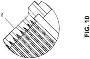
- the filter medium 302 is defined by slots formed in the filter medium-defining counterpart 300 by milling. As depicted in Figure 7 , an example filter medium 302 is formed by milling a number of slots along the circumferential surface of the filter medium-defining counterpart 300. As depicted in Figure 7 , in some embodiments, the filter medium 302 is continuous about the entire circumference of a portion of the filter medium- defining counterpart 300. In some embodiments, for example, the filter medium 302 is not continuous about the entire circumference of a portion of the filter medium-defining counterpart 300. In some embodiments, for example, the filter medium 302 is staggered circumferentially about a portion of the filter medium-defining counterpart 300.
- the filter medium 302 is in the form of a porous material that is integrated within an aperture of the filter medium-defining counterpart 300.
- the filter medium 302 is manufactured by machining of the filter medium-defining counterpart 300.
- a threading with an inverted V edge 308 is machined onto an inner surface of the filter medium 302, and longitudinal slots are machined along the length of the outer surface, as depicted in Figures 7 and 8 .
- the inverted V edge 308 mitigates trapping of particles that flow through the filter medium 302, and reduces clogging of the filter medium 302.
- the threading with the inverted V edge 308 and the longitudinal slots are co operatively configured to provide structural support to the filter medium 302.
- a filter medium-positioning system 2511 is provided for effecting retention of the filter medium-defining part 251, relative to the housing 202, for effecting filtering of solids, from hydrocarbon material being produced from the subterranean formation 100, by the filtering medium 302.
- the filter medium-positioning system 2511 includes a first positioning system counterpart 2512 and a second positioning system counterpart 2513.
- the first positioning system counterpart 2512 is a filter medium-defining part-positioning profile 236 defined by the housing 202
- the second positioning system counterpart 2513 is a retainable profile engager 304 defined by the filter medium-defining part 251.
- the retainable profile engager 304 is configured for becoming disposed within the filter medium-defining part-retaining profile 236 for effecting retention of the filter medium-defining part 251 relative to the housing 202.
- the flow communicator 210, the filter medium 302, the filter medium-defining part-retaining profile 236, and the retainable profile engager 304 are co-operatively configured such that, while the filter medium-defining part 251 is being displaced relative to the filter medium-defining part- retaining profile 236 (for example, along an axis that is parallel to the axis 226), in response to alignment of the retainable profile engager 304 within the filter medium-defining part-retaining profile 236, the retainable profile engager 304 becomes disposed within the filter medium- defining part-retaining profile 236, with effect that the filtering medium 302 becomes disposed relative to the flow communicator 210 (for example, the filtering medium 302 becomes disposed in alignment with the flow communicator 210), such that retention of the filtering medium 302, relative to the flow communicator 210, is
- the surface 2202 is angled in a direction towards an uphole end 200A of the flow control apparatus 200.
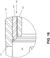
- the surface 2202 is complementary with a surface of the retainable profile engager 304, such as a surface 3042, as depicted in Figures 19 and 22 , wherein the surface 2202 and a surface of the retainable profile engager 304 are co operatively configured such that, in response to the receiving of the retainable profile engager 304 within the recess 220, the retention of the retainable profile engager 304 is effectible upon engagement of the surface 2202 and the surface of the retainable profile engager 304, As depicted in Figures 19 , 20 , and 22 , the surface 2202 is angled with respect to the axis 226.
- the angles defined between the surfaces 2202 and 3042 relative to the central longitudinal axis 226 of the housing 202 and the central longitudinal axis 316 of the filter medium-defining part 251, respectively are based on, among other considerations, the amount of force to be applied to the filter medium-defining part 251 to displace the filter medium-defining part 251, the amount of force to be applied to the filter medium-defining part 251 to release the filter medium-defining part 251 from retention, the amount of displacement of the filter medium-defining part 251, and the amount of force to be resisted to maintain retention of the filter medium-defining part 251 and the housing 202 by the disposition of the retainable profile engager 304 within the filter medium-defining part-retaining profile 236, during operation of the flow control apparatus 200.
- the surface 2202 is an angled surface relative to a surface 2204 of the filter medium-defining part-retaining profile-defined recess 220, and the entire surface 2202 is angled relative to the surface 2204. Where the surface 2202 and the surface 2204 meet, a knife edge may be defined.
- the surface 3042 is an angled surface relative to a surface 3043 of the of the retainable profile engager 304, and the entire surface 3042 is angled relative to the surface 3043. Where the surface 3042 and the surface 3043 meet, a knife edge may be defined.
- the perpendicular portion 2206 is disposed between the surface 2204 and the angled portion 2208 of the surface 2202, such that the knife edge is absent or reduced at the joining of the surface 2202 and the surface 2204.
- the surface 3042 has an angled portion 3048 and a perpendicular portion 3046, where the perpendicular portion 3046 of the surface 3042 is perpendicular, or substantially perpendicular, relative to the central longitudinal axis 316 of the filter medium- defining part 251, corresponds with the perpendicular portion 2206 of the surface 2202.
- the disposition of the engager members 304A within the filter medium-defining part-retaining profile 236 is established in response to alignment between the engager members 304A and the filter medium-defining part-retaining profile 236.
- the material bias of the respective collet spring 332 urges the engager member 304A into disposition within the filter medium-defining part-retaining profile 236, as depicted in Figures 19 and 22 .
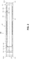
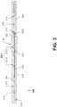
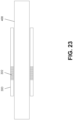
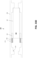
- the flow control apparatus 200 is configurable in an installation configuration (see Figures 2 and 23 ), an open configuration (see Figures 15 and 24 ), a closed configuration (see Figures 17 and 25 ), and a production configuration (see Figures 21 and 26 ).
- the filter medium 302 is disposed relative to the flow communicator 210 (for example, there is an absence of alignment between the filter medium 302 and the flow communicator 210) such that, while the treatment material is being injected into the subterranean formation via the flow communicator 210, there is an absence of filtering, by the filter medium 302, of solid material from the fluid material being conducted between the housing passage 224 and the subterranean formation via the flow communicator 210.
- the flow controller 250 is manipulated such that the flow control apparatus 200 becomes disposed in the closed configuration. Similar to the installation configuration, in the closed configuration, the flow communicator 210 is disposed in the closed condition. Disposition of the flow communicator 210 in the closed condition is with effect that the flow controller 250 is disposed relative to the flow communicator 210 such that there is an absence of flow communication, via the flow communicator 210, between the housing passage 224 and the subterranean formation 100.
- the flow controller 250 includes a filter medium- defining counterpart 300, and the filter medium-defining counterpart 300 is defined by the filter medium-defining part 251.
- the flow controller 250 also includes a shroud-defining counterpart 400.
- the filter medium-defining counterpart 300 and the shroud-defining counterpart 400 are positionable relative to one another such that the apparatus 200 is configurable in a plurality of configurations, as described above.
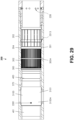
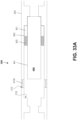
- the filter medium-defining counterpart 300 defines a filter medium-defining counterpart flow regulator 300A (see Figures 5 , 29 , 31 , and 32 ) and, co-operatively, the shroud-defining counterpart 400 defines a shroud-defining counterpart flow regulator 400A (see Figures 12 , 29 , 31 , and 32 ).
- the filter medium-defining counterpart flow regulator 300A includes the filter medium 302.
- an uphole-disposed sealed interface is defined by an uphole-disposed sealing member 222 that is sealingly disposed between the shroud-defining counterpart 400 and the housing 202 at the uphole end of the flow controller 250, as depicted in Figure 2 .
- the housing 202 for example, the top sub 204, defines a recess to receive the uphole-disposed sealing member 222.
- a downhole-disposed sealed interface is defined by a downhole-disposed sealing member 222 that is sealingly disposed between the shroud-defining counterpart 400 and the housing 202 at the downhole end of the flow controller 250.
- the downhole-disposed sealing member 222 is received in a recess defined by the housing 202, for example, the outer barrel 206 or the bottom sub 208.
- the shroud-defining counterpart 400 is disposed relative to the filter medium-defining counterpart 300 such that the shielding of the filter medium 302 from the housing passage 224 is effected by the shroud 418.
- the filter medium-defining counterpart 300 is disposed relative to the housing 202 such that there is shielding of the filter medium 302 from the external environment by the housing 202.
- the shielding from the external environment is effected by occlusion of the filter medium 302 by the housing 202.
- the filter medium 302 is shielded from the housing passage 224, the external environment, and the space defined between the housing 202 and the flow controller 250 such that the filter medium 302 is unclogged, or substantially unclogged and free, or substantially free, of debris, and the filter medium-defining counterpart 300 may be displaced through a clean, or substantially clean, displacement pathway during operation of the flow control apparatus 200.
- the relative disposition is with effect that the shroud-defining counterpart 400 is disposed for transmitting a force (such as, for example, in response to a force that is applied to the shroud- defining counterpart 400 in a direction that is parallel to the axis 415) to the filter medium- defining counterpart such that the filter medium-defining counterpart 300 is translatable with the shroud-defining counterpart 400.
- a force such as, for example, in response to a force that is applied to the shroud- defining counterpart 400 in a direction that is parallel to the axis 415
- the housing 202, the filter medium-defining counterpart 300, and the shroud-defining counterpart 400 are co-operatively configured such that, while the shroud-defining counterpart engager 330 of the filter medium-defining counterpart 300 is aligned with the filter medium-defining counterpart-coupling profile 402 of the shroud- defining counterpart 400, urging of the co-operative disposition between the shroud-defining counterpart engager 330 and the filter medium-defining counterpart-coupling profile 402 (as will be explained below) is effected.
- Each one of the one or more coupling-stimulating profile engager members 336 is configured for engaging the coupling-stimulating profile 234, while the shroud-defining counterpart engager 330 of the filter medium-defining counterpart 300 is disposed in alignment with the filter medium-defining counterpart-coupling profile 402 of the shroud-defining counterpart 400, with effect that the urging, of the co-operative disposition between the shroud-defining counterpart engager 330 and the filter medium-defining counterpart-coupling profile 402, is effected.
- each one of the one or more coupling-stimulating profile engager members 336 is defined by a protuberance 338, as depicted in Figures 4 , 7 , and 9 , and the protuberance 338 extends outwardly (such as, for example, radially outwardly relative to the axis 316).
- the housing 202, the filter medium-defining counterpart 300, and the shroud-defining counterpart 400 are co-operatively configured such that, while: (i) the one or more coupling-stimulating profile engager members 336 of the filter medium-defining counterpart 300 are engaging the coupling-stimulating profile 234 of the housing 202, and (ii) the shroud-defining counterpart engager 330 of the filter medium-defining counterpart 300 is aligned with the filter medium-defining counterpart-coupling profile 402 of the shroud-defining counterpart 400, the urging, of the co-operative disposition between the shroud-defining counterpart engager 330 and the filter medium-defining counterpart-coupling profile 402, is effected.
- Each one of the one or more shroud-defining counterpart engager members 306 (for example, the one or more protuberances 334), independently, extends from a respective one of the collet springs 332.
- each one of the one or more shroud-defining counterpart engager members 306 of the filter medium-defining counterpart 300 independently, is stiffer than the respective collet spring 332 from which it extends.
- each one of the one or more coupling stimulating profile engager members 336 (for example, the one or more protuberances 338) of the filter medium-defining counterpart 300, independently, extends from a respective one of the collet springs 332, such that, for each one of the one or more shroud-defining counterpart engager members 306, there is associated a corresponding coupling stimulating profile engager 336.
- each one of the one or more coupling stimulating profile engager members 336 independently, is stiffer than the respective collet spring 332 from which it extends.
- the surface 420 and the surface 422 are positioned in opposition of each other.
- the surface 420 is positioned uphole relative to the surface 422, such that the surface 420 is an uphole surface 420 and the surface 422 is a downhole surface 422.
- the one or more surfaces 420 and 422 are tapered, chamfered, bevelled, or angled.
- the one or more surfaces 420 or 422 applies a force to the one or more shroud-defining counterpart engager members 306 that urges displacement of the filter medium-defining counterpart 300 to promote the defeating of the co-operative disposition between the filter medium-defining counterpart 300 and the shroud-defining counterpart 400.
- the defeating is effected in response to displacement of the shroud-defining counterpart 400, relative to the filter medium-defining counterpart 300, along an axis that is parallel to the axis 226.
- the surfaces 420 and 422 define angles between 45° and 73° relative to the central longitudinal axis 415 of the shroud-defining counterpart 400. In some embodiments, for example, the surfaces 420 and 422 define angles that are less than 45° to the central longitudinal axis 415 of the shroud- defining counterpart 400. In some embodiments, for example, the surfaces 420 and 422 define angles that are greater than 73° to the central longitudinal axis 415 of the shroud-defining counterpart 400.
- a wellbore material transfer system 10 for conducting material from the surface 101 to a subterranean formation 100 via a wellbore 102 of a well 120, from the subterranean formation 100 to the surface 10 via the wellbore 102, or between the surface 10 and the subterranean formation 100 via the wellbore 102.
- the subterranean formation 100 is a reservoir that contains hydrocarbon material.
- Exemplary chemical additives include acids, sodium chloride, polyacrylamide, ethylene glycol, borate salts, sodium and potassium carbonates, glutaraldehyde, guar gum and other water-soluble gels, citric acid, and isopropanol.
- the treatment material is supplied to effect hydraulic fracturing of the reservoir.
- a cased-hole completion involves running casing down into the wellbore 102 through the production zone.
- the casing 104A at least contributes to the stabilization of the subterranean formation 100 after the wellbore 102 has been completed, by at least contributing to the prevention of the collapse of the subterranean formation 100 that is defining the wellbore 102.
- the casing 104A includes one or more successively deployed concentric casing strings, each one of which is positioned within the wellbore 102, having one end extending from the wellhead 108.
- the casing strings are typically run back up to the surface.
- each casing string includes a plurality of jointed segments of pipe. The jointed segments of pipe typically have threaded connections.
- the conduction of fluids between the surface 10 and the subterranean formation 100 is effected via the passage 106 of the wellbore string 104.
- the flow control apparatus 200 includes a housing 202, as depicted in Figure 2 and Figure 27 .
- the housing 202 includes a housing passage 224.
- the housing 202 includes an uphole opening 201 at an uphole end 200A of the apparatus 200, and a downhole opening 203 at a downhole end 200B of the apparatus 200, and the housing passage 224 extends between the uphole opening 201 and the downhole opening 203.
- the flow control apparatus 200 is configured for integration within the wellbore string 104 such that the wellbore string passage 106 includes the passage 224.
- the flow control apparatus 200 includes the flow controller 250 for controlling flow communication between the housing passage 224 and the flow communicator 210.
- the flow controller 250 is received within the housing 202 and is displaceable within the housing passage 224 relative to the flow communicator 210.
- the flow controller 250 is configured for controlling conducting of material, such as, for example, flow of material, via the flow communicator 210, between the passage 224 and an environment external to the flow control apparatus 200, such as, for example, the subterranean formation 100.
- the flow controller 250 is configured for controlling the conducting of material (such as, for example, material flow) through the flow communicator 210.
- Such coupling relationship enables translation of the sliding sleeve 301 with the sliding sleeve 401, in response to application of a force to the sliding sleeve 401 via a shifting tool (such as, for example, a force from fluid within the wellbore string passage that is transmitted to the sliding sleeve 401 by the shifting tool).
- a shifting tool such as, for example, a force from fluid within the wellbore string passage that is transmitted to the sliding sleeve 401 by the shifting tool.
- the sliding sleeve 401 is disposed for engagement with a shifting tool, with effect that the sliding sleeve 401 becomes translatable with the shifting tool.
- the releasable retention of the flow controller 250 is for preventing inadvertent displacement of the flow controller 250 while the apparatus is being run in hole within the wellbore 102.
- the frangible interlocking member 228 is a shear pin.
- the releasable retention is configured such that mechanical fracture of the one or more frangible interlocking members 228 is effectible in response to application of a sufficient force to the sliding sleeve 401 (such as, for example, by a shifting tool, see below), with effect that the sliding sleeve 401 becomes released from retention relative to the housing 202.
- the direction of the applied force is in the first direction (e.g. the downhole direction), such that, after the release from the retention, continued application of force in the first direction effects a change in configuration of the flow control apparatus 200 from the installation configuration to the open configuration.
- the change in disposition of the flow controller 250 includes displacement of the occluding portion 310 of the sliding sleeve 301, relative to the flow communicator 210, with effect that the flow communicator 210 becomes disposed in the open condition. Because the sliding sleeve 301 and the sliding sleeve 401 are coupled together. In the first coupled configuration, the sliding sleeve 301 is translatable with the sliding sleeve 401 while the sliding sleeve 401 is being displaced, relative to the flow communicator 210, in the first direction (e.g. the downhole direction).
- the first direction e.g. the downhole direction
- the flow control apparatus 200 in response to application of a force to the sliding sleeve 401 via the shifting tool in a first direction (for example, the downhole direction), an opening displacement of the sliding sleeve 401, relative to the flow communicator 210, is effected in the first direction, and the sliding sleeve 301, being coupled to the sliding sleeve 401, translates with the sliding sleeve 401.
- the flow controller 300 is sufficiently displaced in the first direction such that the flow communicator 210 becomes disposed in the open condition.
- the first direction is parallel to a longitudinal axis 226 of the housing passage 224.
- the defeating of the coupling between the sliding sleeve 301 and the sliding sleeve 401 includes fracturing of the one or more frangible interlocking members 2600.
- the sliding sleeve 401 is disposed for engagement with a shifting tool (such as, for example, the same shifting tool used to effect the opening displacement), with effect that the sliding sleeve 401 becomes translatable with the shifting tool, and translates with the shifting tool, in response to application of a force (such as, for example, a pulling up force exerted via coiled tubing) to the shifting tool in the second direction (e.g. the uphole direction).
- a shifting tool such as, for example, the same shifting tool used to effect the opening displacement
- a force such as, for example, a pulling up force exerted via coiled tubing
- an uphole end of the sliding sleeve 301 defines a knife edge 324, as depicted in Figure 5 .
- the knife edge 324 is configured to clean the housing passage 224, for example, clean the housing passage 224 of sand after a stimulation process has been conducted. While the sliding sleeve 301 is translating with the sliding sleeve 401 during the closing displacement, for changing the configuration of the flow control apparatus 200 from the open configuration to the closed configuration, the knife edge 324 is disposed for effecting such cleaning of the housing passage 224.
- the defeating of the coupling between the sliding sleeve 301 and the sliding sleeve 401 includes a deflection of the shroud-defining counterpart engager 330 relative to the open configuration profile feature 406.
- the deflection of the shroud-defining counterpart engager 330 relative to the open configuration profile feature 406 is effected by deflection of the resilient portion 333 of the sliding sleeve 301.
- the coupling between the sliding sleeve 301 and the sliding sleeve 401, effected by the coupling system 5300, is defeated.
- the flow controller 250 is disposed in the second uncoupled configuration, and the sliding sleeve 301 is retained relative to the flow communicator 210 such that displacement of the sliding sleeve 301, relative to the flow communicator 210, is being prevented, (ii) the closing displacement of the sliding sleeve 401, relative to the flow communicator 210, continues to be being urged (e.g. by the shifting tool) in the second direction (e.g.
- the housing 202, the flow communicator 210, and the flow controller 250 are co-operatively configured such that, while the flow control apparatus 200 is disposed in the closed configuration, in response to application of a force to the sliding sleeve 401 in the first direction: (i) the releasable coupling of the sliding sleeve 301 and sliding sleeve 401 is defeated; and (ii) there is an absence of release of the sliding sleeve 301 from the retention relative to the housing 202.
- the sliding sleeve 301 includes the occluding portion 310, and the closing of the flow communicator 210 is effected by the occluding portion 310.
- the occluding portion 310 is disposed relative to the flow communicator 210 for effecting disposition of the flow communicator 210 in the closed condition.
- the flow controller 250 includes a filter medium-defining counterpart 300 and a shroud-defining counterpart 400, in some embodiments, for example, the flow controller 250 further includes a flow communicator- occluding counterpart 3100, and the flow communicator-occluding counterpart 3100 includes a flow regulator 3100A, and the flow regulator 3100A includes the occluding portion 310.
- the flow regulator 300A of the filter medium-defining counterpart 300 does not include the occluding portion 310, and the occluding portion 310 is disposed on a part (i.e. the flow communicator-occluding counterpart 3100) that is separate from the filter medium-defining counterpart 300.
- the occluding portion 310, of the sliding sleeve 3101 effects occluding of the flow communicator 210, such that the flow communicator 210 is disposed in the closed condition.
- the sliding sleeve 3101 and the shroud-defining counterpart 400 are coupled together by one or more frangible interlocking members 2281 (e.g. one or more shear pins).
- the stop 214, the flow controller 250, and the flow communicator 210 are further co-operatively configured such that, while the flow control apparatus 200 is disposed in the installation condition, in response to a displacement of the sliding sleeve 301, relative to the flow communicator 210, in the first direction (e.g. the downhole direction), the sliding sleeve 3101 becomes disposed in abutting engagement with the sliding sleeve 301, and while the sliding sleeve 3101 is disposed in abutting engagement with the sliding sleeve 301, in response to a continuing displacement of the sliding sleeve 301, relative to the flow communicator 210, in the first direction (e.g. the downhole direction):
- the sliding sleeve 3101 also becomes translatable with the sliding sleeve 401 while the sliding sleeve 401 is being displaced, relative to the flow communicator 210, in the second direction (e.g. the uphole direction).
- sliding sleeve 401 is disposed in the uncoupled condition
- sliding sleeve 301 is disposed in abutting engagement with the stop 214 such that displacement of the sliding sleeve 301, relative to the stop 214, in the first direction (e.g. the downhole direction) is being prevented
- displacement of the sliding sleeve 401, relative to the flow communicator 210 continues being urged (e.g. by the shifting tool) in the first direction (e.g.
- the stop 216 is provided for becoming disposed in abutting engagement with the sliding sleeve 401 for limiting (e.g. preventing) displacement of the sliding sleeve 401, relative to the flow communicator 210, in the first direction, upon the coupling of the sliding sleeves 301, 401 having been established.
- the sliding sleeve 301, the sliding sleeve 401, and the stop 216 are co-operatively configured such that the abutting engagement of the sliding sleeve 401 with the stop 216 is effected upon the establishment of the releasable coupling of the sliding sleeve 301 and the sliding sleeve 401 via the coupling system 5300.
- the flow communicator 210 and the flow controller 250 are co operatively disposed such that the housing 202 shields the filter medium 302 from the external environment, such as the subterranean formation 100.
- the shielding is effected by occlusion of the filter medium 302 by the housing 202.
- the sliding sleeve 3101 is disposed in abutting engagement with the sliding sleeve 301, the sliding sleeve 3101 and the sliding sleeve 301 behave like a single unit during the transition of the flow control apparatus 200 from the open configuration to the closed configuration, and also during the transition of the flow control apparatus 200 from the closed configuration to the production configuration.
- the occluding of the filter medium 302 is being effected by the shroud 418.
- the sliding sleeve 301 and sliding sleeve 401 are co- operatively disposed such that the shroud 418 shields the filter medium 302 from material within the housing passage 224.
- the shielding is effected by occlusion of the filter medium 302 by the sliding sleeve 401, such as the shroud 418.
- sliding sleeve 401 is retained to the housing 202 with a collet retainer, in a similar way to that described in U.S. Patent Application Serial No. 14/830,531 , which is hereby incorporated by reference in its entirety.
- the sliding sleeve 301 is also retained to the housing 202.
- the sliding sleeve 301 is releasably coupled to the sliding sleeve 401 via the coupling system 5300, such that the sleeve 301 is translatable with the sleeve 401 (such as, for example, while the sleeve 401 is being displaced by a shifting tool).
- the sliding sleeves 301, 401 are disposed in a configuration equivalent to that of the sliding sleeves 301, 401 of the embodiment illustrated in Figures 1 to 27 , when disposed in the second coupled configuration (i.e. with the flow control apparatus of Figures 1 to 27 disposed in the open configuration), with the exception that there is an absence of an occluding portion 310 in the sliding sleeve 301.
- the transition of the flow control apparatus 200 from the open configuration to the closed configuration is effectible in a manner equivalent to the corresponding transition of the embodiment illustrated in Figures 1 to 27 (with effect, amongst other things, that the sliding sleeve 301 becomes retained relative to the housing 202 by the filter medium-positioning system 2511, for effecting filtering of solids, from hydrocarbon material being produced from the subterranean formation 100, by the filtering medium 302, while the apparatus is disposed in the production configuration), and also the transition of the flow control apparatus 200 from the closed configuration to the production configuration is effectible in a manner equivalent to the corresponding transition of the embodiment illustrated in Figures 1 to 27 .
Landscapes
- Life Sciences & Earth Sciences (AREA)
- Engineering & Computer Science (AREA)
- Geology (AREA)
- Mining & Mineral Resources (AREA)
- Physics & Mathematics (AREA)
- Environmental & Geological Engineering (AREA)
- Fluid Mechanics (AREA)
- General Life Sciences & Earth Sciences (AREA)
- Geochemistry & Mineralogy (AREA)
- Filtering Of Dispersed Particles In Gases (AREA)
Claims (17)
- Appareil de régulation de débit (200), configurable dans au moins une configuration fermée et une configuration de production, comprenant :un boîtier (202) comprenant un passage de boîtier (224) et un dispositif de communication de débit (210) pour effectuer une communication de débit entre un environnement externe au boîtier et le passage de boîtier ;un dispositif de régulation de débit (250) pour réguler la communication de débit, par l'intermédiaire du dispositif de communication de débit, entre le passage de boîtier et l'environnement externe, comprenant :une contrepartie de définition de milieu filtrant (300) définissant un milieu filtrant (302) ; etune contrepartie de définition de carénage (400) définissant un carénage (418) ;caractérisé en ce que :alors que l'appareil de régulation de débit est disposé dans la configuration fermée, le dispositif de communication de débit et le dispositif de régulation de débit sont disposés en coopération de sorte que le dispositif de communication de débit soit disposé dans un état fermé, et la contrepartie de définition de milieu filtrant et la contrepartie de définition de carénage sont disposées en coopération de sorte que le carénage protège le milieu filtrant du matériau à l'intérieur du passage de boîtier ; etalors que l'appareil de régulation de débit est disposé dans la configuration de production, le dispositif de communication de débit et le dispositif de régulation de débit sont disposés en coopération de sorte que la communication de débit, par l'intermédiaire du milieu filtrant, soit effectuée entre l'environnement externe et le passage de boîtier.
- Appareil de régulation de débit selon la revendication 1, dans lequel, alors que l'appareil de régulation de débit est disposé dans la configuration de production, le dispositif de communication de débit et le dispositif de régulation de débit sont en outre disposés en coopération de sorte qu'il existe une absence d'obturation du milieu filtrant par le carénage.
- Appareil de régulation de débit selon la revendication 1 ou 2, dans lequel la contrepartie de définition de carénage est imbriquée dans la contrepartie de définition de milieu filtrant.
- Appareil de régulation de débit selon l'une quelconque des revendications 1 à 3 ; dans lequel chacune de la contrepartie de définition de milieu filtrant et de la contrepartie de définition de carénage, indépendamment, se présente sous la forme d'un manchon.
- Appareil de régulation de débit selon l'une quelconque des revendications 1 à 4, et pouvant en outre être configuré dans une configuration d'installation, dans lequel :alors que l'appareil de régulation de débit est disposé dans la configuration d'installation :(i) le dispositif de communication de débit et le dispositif de régulation de débit sont disposés en coopération de telle sorte que le dispositif de communication de débit soit disposé dans un état fermé ;(ii) la contrepartie de définition de milieu filtrant et la contrepartie de définition de carénage sont disposées en coopération de telle sorte que le carénage protège le milieu filtrant du matériau à l'intérieur du passage du boîtier ; et(iii) le dispositif de régulation de débit est fixé de manière libérable au boîtier avec un organe de verrouillage cassable (228).
- Appareil de régulation de débit selon la revendication 5, dans lequel dans la configuration d'installation, le dispositif de communication de débit et le dispositif de régulation de débit sont disposés en coopération de sorte que le boîtier protège le milieu filtrant de l'environnement externe.
- Appareil de régulation de débit selon la revendication 5 ou 6, dans lequel la contrepartie de définition de milieu filtrant définit un régulateur de débit de contrepartie de définition de milieu filtrant (300A) comprenant le milieu filtrant (302) et une portion d'obturation (310).
- Appareil de régulation de débit selon la revendication 5 ou 6, dans lequel le dispositif de régulation de débit comprend en outre une contrepartie d'obturation de dispositif de communication de débit (3100), et la contrepartie d'obturation de dispositif de communication de débit comprend un régulateur de débit (3100A), et le régulateur de débit comprend une portion d'obturation disposée sur une partie qui est séparée de la contrepartie de définition de milieu filtrant.
- Appareil de régulation de débit selon l'une quelconque des revendications 6 à 8, dans lequel le dispositif de communication de débit est disposé dans l'état fermé alors que le dispositif de communication de débit est obturé par la portion d'obturation.
- Appareil de régulation de débit selon la revendication 6 ou 7, dans lequel dans la configuration d'installation, il existe une absence d'alignement entre une quelconque portion du milieu filtrant et le dispositif de communication de débit.
- Appareil de régulation de débit selon l'une quelconque des revendications 1 à 10, et pouvant en outre être configuré dans une configuration ouverte, dans lequel :
alors que l'appareil de régulation de débit est disposé dans la configuration ouverte, le dispositif de communication de débit et le dispositif de régulation de débit sont disposés en coopération de sorte que le dispositif de communication de débit soit disposé dans un état ouvert, et la contrepartie de définition de milieu filtrant et la contrepartie de définition de carénage sont disposées en coopération de sorte que le carénage protège le milieu filtrant du matériau à l'intérieur du passage du boîtier, et le dispositif de communication de débit et le dispositif de régulation de débit sont disposés en coopération de sorte que le boîtier protège le milieu filtrant de l'environnement externe. - Appareil de régulation de débit selon la revendication 11, comprenant en outre un système de positionnement de milieu filtrant (2511) pour effectuer la rétention de la contrepartie de définition de milieu filtrant par rapport au boîtier, et un système d'accouplement (5300) pour effectuer un accouplement libérable de la contrepartie de définition de milieu filtrant et de la contrepartie de définition de carénage.
- Appareil de régulation de débit selon la revendication 12, dans lequel le système de positionnement de milieu filtrant comprend une première contrepartie de système de positionnement (2512) ayant un profil de retenue de partie de définition de milieu filtrant (236) défini par le boîtier (202), et une seconde contrepartie de système de positionnement (2513) ayant un élément de mise en prise de profil de retenue (304) défini par la contrepartie de définition de milieu filtrant, l'élément de mise en prise de profil de retenue étant configuré pour être disposé à l'intérieur du profil de retenue de partie de définition de milieu filtrant pour effectuer une retenue de la contrepartie de définition de milieu filtrant par rapport au boîtier.
- Appareil de régulation de débit selon la revendication 12, dans lequel le système d'accouplement comprend une première contrepartie de système d'accouplement (5301) ayant un élément de mise en prise de contrepartie de définition de carénage (330), et comprend en outre une seconde contrepartie de système d'accouplement (5302) ayant un profil d'accouplement de contrepartie de définition de milieu filtrant (402), l'élément de mise en prise de contrepartie de définition de carénage étant configuré pour être disposé à l'intérieur du profil d'accouplement de contrepartie de définition de milieu filtrant, de sorte que la contrepartie de définition de milieu filtrant (300) et la contrepartie de définition de carénage (400) soient disposées dans l'accouplement libérable de sorte que la contrepartie de définition de milieu filtrant puisse être translatée avec la contrepartie de définition de carénage.
- Appareil de régulation de débit selon la revendication 12, dans lequel, dans la configuration d'installation, le dispositif de régulation de débit est retenu de manière libérable par rapport au boîtier par un ou plusieurs organes de verrouillage cassables, la fracture mécanique des un ou plusieurs organes de verrouillage cassables pouvant être effective en réponse à l'application d'une force à la contrepartie de définition de carénage dans une première direction pour effectuer un changement de configuration de la contrepartie de définition de milieu filtrant et de la contrepartie de définition de carénage par rapport à l'accouplement libérable, et pour effectuer un changement de configuration de l'appareil de régulation de débit de la configuration d'installation à la configuration ouverte.
- Appareil de régulation de débit selon la revendication 15, dans lequel, dans la configuration ouverte, le dispositif de régulation de débit est disposé pour manipulation, en réponse à une force exercée sur la contrepartie de définition de carénage dans une seconde direction, opposée à la première direction, pour effectuer un changement de configuration de l'appareil de régulation de débit de la configuration ouverte à la configuration fermée.
- Appareil de régulation de débit selon la revendication 16, dans lequel, dans la configuration fermée, le système de positionnement de milieu filtrant effectue la rétention de la contrepartie de définition de milieu filtrant par rapport au boîtier, et dans lequel la contrepartie de définition de carénage est désaccouplée de la contrepartie de définition de milieu filtrant en réponse à une force exercée sur la contrepartie de définition de carénage dans la première direction pour effectuer un changement de configuration de l'appareil de régulation de débit de la configuration fermée à la configuration de production.
Applications Claiming Priority (3)
| Application Number | Priority Date | Filing Date | Title |
|---|---|---|---|
| US201962815595P | 2019-03-08 | 2019-03-08 | |
| US201962946155P | 2019-12-10 | 2019-12-10 | |
| PCT/CA2020/050298 WO2020181364A1 (fr) | 2019-03-08 | 2020-03-06 | Régulateur de débit de fond de trou |
Publications (3)
| Publication Number | Publication Date |
|---|---|
| EP3935261A1 EP3935261A1 (fr) | 2022-01-12 |
| EP3935261A4 EP3935261A4 (fr) | 2022-08-10 |
| EP3935261B1 true EP3935261B1 (fr) | 2025-04-16 |
Family
ID=72427068
Family Applications (1)
| Application Number | Title | Priority Date | Filing Date |
|---|---|---|---|
| EP20769775.6A Active EP3935261B1 (fr) | 2019-03-08 | 2020-03-06 | Régulateur de débit de fond de trou |
Country Status (5)
| Country | Link |
|---|---|
| US (2) | US11867025B2 (fr) |
| EP (1) | EP3935261B1 (fr) |
| CA (1) | CA3132876A1 (fr) |
| DK (1) | DK3935261T3 (fr) |
| WO (1) | WO2020181364A1 (fr) |
Family Cites Families (42)
| Publication number | Priority date | Publication date | Assignee | Title |
|---|---|---|---|---|
| US3811500A (en) * | 1971-04-30 | 1974-05-21 | Halliburton Co | Dual sleeve multiple stage cementer and its method of use in cementing oil and gas well casing |
| US3768556A (en) * | 1972-05-10 | 1973-10-30 | Halliburton Co | Cementing tool |
| US4429747A (en) * | 1981-09-01 | 1984-02-07 | Otis Engineering Corporation | Well tool |
| EP0327432B1 (fr) * | 1988-01-29 | 1997-09-24 | Institut Français du Pétrole | Procédé et dispositif pour commander hydrauliquement et sélectivement, au moins deux outils ou instruments d'un dispositif, vanne permettant la mise en oeuvre de la méthode ou utilisant ledit dispositif |
| GB2358657B (en) * | 1997-07-28 | 2001-10-03 | Smith International | Bypass valve closing means |
| US6422317B1 (en) * | 2000-09-05 | 2002-07-23 | Halliburton Energy Services, Inc. | Flow control apparatus and method for use of the same |
| US20090084553A1 (en) * | 2004-12-14 | 2009-04-02 | Schlumberger Technology Corporation | Sliding sleeve valve assembly with sand screen |
| US7387165B2 (en) * | 2004-12-14 | 2008-06-17 | Schlumberger Technology Corporation | System for completing multiple well intervals |
| US7325617B2 (en) * | 2006-03-24 | 2008-02-05 | Baker Hughes Incorporated | Frac system without intervention |
| US7921915B2 (en) | 2007-06-05 | 2011-04-12 | Baker Hughes Incorporated | Removable injection or production flow equalization valve |
| US7575058B2 (en) * | 2007-07-10 | 2009-08-18 | Baker Hughes Incorporated | Incremental annular choke |
| US7971646B2 (en) * | 2007-08-16 | 2011-07-05 | Baker Hughes Incorporated | Multi-position valve for fracturing and sand control and associated completion methods |
| US7703510B2 (en) * | 2007-08-27 | 2010-04-27 | Baker Hughes Incorporated | Interventionless multi-position frac tool |
| US7866402B2 (en) * | 2007-10-11 | 2011-01-11 | Halliburton Energy Services, Inc. | Circulation control valve and associated method |
| US8127847B2 (en) | 2007-12-03 | 2012-03-06 | Baker Hughes Incorporated | Multi-position valves for fracturing and sand control and associated completion methods |
| US8833468B2 (en) * | 2009-03-04 | 2014-09-16 | Halliburton Energy Services, Inc. | Circulation control valve and associated method |
| US20110284232A1 (en) * | 2010-05-24 | 2011-11-24 | Baker Hughes Incorporated | Disposable Downhole Tool |
| US8297358B2 (en) * | 2010-07-16 | 2012-10-30 | Baker Hughes Incorporated | Auto-production frac tool |
| US8776884B2 (en) * | 2010-08-09 | 2014-07-15 | Baker Hughes Incorporated | Formation treatment system and method |
| US8789600B2 (en) * | 2010-08-24 | 2014-07-29 | Baker Hughes Incorporated | Fracing system and method |
| US9133684B2 (en) * | 2011-05-02 | 2015-09-15 | Raymond Hofman | Downhole tool |
| US9611719B2 (en) * | 2011-05-02 | 2017-04-04 | Peak Completion Technologies, Inc. | Downhole tool |
| US8267178B1 (en) * | 2011-09-01 | 2012-09-18 | Team Oil Tools, Lp | Valve for hydraulic fracturing through cement outside casing |
| GB201205985D0 (en) * | 2012-04-03 | 2012-05-16 | Petrowell Ltd | Frac packing tools |
| US9341046B2 (en) * | 2012-06-04 | 2016-05-17 | Schlumberger Technology Corporation | Apparatus configuration downhole |
| SG11201500031TA (en) * | 2012-08-29 | 2015-02-27 | Halliburton Energy Services Inc | A reclosable sleeve assembly and methods for isolating hydrocarbon production |
| US10107076B2 (en) * | 2012-11-21 | 2018-10-23 | Peak Completion Technologies, Inc | Downhole tools, systems and methods of using |
| US9856714B2 (en) * | 2013-07-17 | 2018-01-02 | Weatherford Technology Holdings, Llc | Zone select stage tool system |
| US9926769B2 (en) * | 2013-11-07 | 2018-03-27 | Baker Hughes, A Ge Company, Llc | Systems and methods for downhole communication |
| US9428991B1 (en) | 2014-03-16 | 2016-08-30 | Elie Robert Abi Aad | Multi-frac tool |
| WO2016101061A1 (fr) * | 2014-12-23 | 2016-06-30 | Ncs Multistage Inc. | Appareil de régulation de débit en fond de puits avec tamis |
| GB2560658A (en) * | 2015-12-31 | 2018-09-19 | Halliburton Energy Services Inc | Downhole tool with alterable structural component |
| US9574421B1 (en) * | 2016-01-04 | 2017-02-21 | Vertice Oil Tools | Methods and systems for a frac sleeve |
| US10260314B2 (en) * | 2016-06-23 | 2019-04-16 | Vertice Oil Tools | Methods and systems for a pin point frac sleeves system |
| WO2018098591A1 (fr) | 2016-12-02 | 2018-06-07 | Dejong Robert N | Tondeuse à lames hélicoïdales rotative |
| WO2018098592A1 (fr) * | 2016-12-02 | 2018-06-07 | Ncs Multistage Inc. | Appareil, systèmes et procédés d'isolation pendant une fracturation hydraulique à plusieurs étapes avec un élément de régulation de débit ayant une caractéristique d'impédance |
| CA3219326A1 (fr) * | 2017-03-07 | 2018-09-13 | Ncs Multistage Inc. | Appareils, systemes et procedes de production d'un materiau hydrocarbone a partir d'une formation souterraine |
| CN106994901B (zh) | 2017-03-09 | 2023-03-21 | 上海蔚来汽车有限公司 | 车辆加电提醒方法和系统 |
| CN110691887B (zh) * | 2017-08-03 | 2022-09-09 | 哈利伯顿能源服务公司 | 井筒流体连通工具 |
| US10400555B2 (en) * | 2017-09-07 | 2019-09-03 | Vertice Oil Tools | Methods and systems for controlling substances flowing through in an inner diameter of a tool |
| US10662739B2 (en) * | 2018-01-01 | 2020-05-26 | Vertice Oil Tools | Methods and systems for a frac sleeve |
| WO2019231658A1 (fr) * | 2018-05-31 | 2019-12-05 | Vertice Oil Tools | Procédés et systèmes pour la cimentation à travers des crépines |
-
2020
- 2020-03-06 CA CA3132876A patent/CA3132876A1/fr active Pending
- 2020-03-06 DK DK20769775.6T patent/DK3935261T3/da active
- 2020-03-06 WO PCT/CA2020/050298 patent/WO2020181364A1/fr not_active Ceased
- 2020-03-06 US US17/437,325 patent/US11867025B2/en active Active
- 2020-03-06 EP EP20769775.6A patent/EP3935261B1/fr active Active
-
2023
- 2023-11-20 US US18/514,906 patent/US12371969B2/en active Active
Also Published As
| Publication number | Publication date |
|---|---|
| CA3132876A1 (fr) | 2020-09-17 |
| US20250163775A1 (en) | 2025-05-22 |
| US11867025B2 (en) | 2024-01-09 |
| WO2020181364A1 (fr) | 2020-09-17 |
| US20220178225A1 (en) | 2022-06-09 |
| EP3935261A4 (fr) | 2022-08-10 |
| DK3935261T3 (da) | 2025-07-21 |
| EP3935261A1 (fr) | 2022-01-12 |
| US12371969B2 (en) | 2025-07-29 |
Similar Documents
| Publication | Publication Date | Title |
|---|---|---|
| US11821286B2 (en) | Apparatuses, systems and methods for producing hydrocarbon material from a subterranean formation | |
| US6571875B2 (en) | Circulation tool for use in gravel packing of wellbores | |
| EP1132571A1 (fr) | Procédé et appareil pour la fracturation et installation de filtre à gravier | |
| EP3237724B1 (fr) | Appareil de régulation de débit en fond de puits avec tamis | |
| US20050121192A1 (en) | Apparatus and method for gravel packing an interval of a wellbore | |
| NO346331B1 (en) | Formation treatment system and method of performing a treatment operation | |
| US12571285B2 (en) | Downhole valve assembly with cement-isolated flowpath | |
| US20220003094A1 (en) | Process for producing hydrocarbon material from a subterranean formation while employing solids control | |
| EP3935261B1 (fr) | Régulateur de débit de fond de trou | |
| EP3814606B1 (fr) | Vannes de fond de trou pouvant être refermées ayant une intégrité d'étanchéité améliorée | |
| US10927641B2 (en) | Apparatuses, systems and methods for treating and producing from multiple zones in a subterranean formation | |
| US12006803B2 (en) | Systems and methods for producing hydrocarbon material from unconsolidated formations | |
| CA3099657C (fr) | Vannes de fond de trou pouvant etre refermees ayant une integrite d'etancheite amelioree | |
| US20200063538A1 (en) | Apparatus, systems and methods for isolation during multistage hydraulic fracturing with flow control member having impedance feature | |
| CA3005195A1 (fr) | Appareil, systemes et methodes d'attenuation de l'accumulation de solides dans un trou de forage pendant la stimulation de formations souterraines | |
| CA3104722A1 (fr) | Appareils de communication de debit en fond de trou |
Legal Events
| Date | Code | Title | Description |
|---|---|---|---|
| STAA | Information on the status of an ep patent application or granted ep patent |
Free format text: STATUS: THE INTERNATIONAL PUBLICATION HAS BEEN MADE |
|
| PUAI | Public reference made under article 153(3) epc to a published international application that has entered the european phase |
Free format text: ORIGINAL CODE: 0009012 |
|
| STAA | Information on the status of an ep patent application or granted ep patent |
Free format text: STATUS: REQUEST FOR EXAMINATION WAS MADE |
|
| 17P | Request for examination filed |
Effective date: 20211007 |
|
| AK | Designated contracting states |
Kind code of ref document: A1 Designated state(s): AL AT BE BG CH CY CZ DE DK EE ES FI FR GB GR HR HU IE IS IT LI LT LU LV MC MK MT NL NO PL PT RO RS SE SI SK SM TR |
|
| DAV | Request for validation of the european patent (deleted) | ||
| DAX | Request for extension of the european patent (deleted) | ||
| A4 | Supplementary search report drawn up and despatched |
Effective date: 20220713 |
|
| RIC1 | Information provided on ipc code assigned before grant |
Ipc: G05D 7/01 20060101ALI20220707BHEP Ipc: E21B 43/12 20060101ALI20220707BHEP Ipc: E21B 43/02 20060101ALI20220707BHEP Ipc: E21B 43/08 20060101AFI20220707BHEP |
|
| GRAP | Despatch of communication of intention to grant a patent |
Free format text: ORIGINAL CODE: EPIDOSNIGR1 |
|
| STAA | Information on the status of an ep patent application or granted ep patent |
Free format text: STATUS: GRANT OF PATENT IS INTENDED |
|
| INTG | Intention to grant announced |
Effective date: 20240516 |
|
| GRAJ | Information related to disapproval of communication of intention to grant by the applicant or resumption of examination proceedings by the epo deleted |
Free format text: ORIGINAL CODE: EPIDOSDIGR1 |
|
| STAA | Information on the status of an ep patent application or granted ep patent |
Free format text: STATUS: REQUEST FOR EXAMINATION WAS MADE |
|
| INTC | Intention to grant announced (deleted) | ||
| GRAP | Despatch of communication of intention to grant a patent |
Free format text: ORIGINAL CODE: EPIDOSNIGR1 |
|
| STAA | Information on the status of an ep patent application or granted ep patent |
Free format text: STATUS: GRANT OF PATENT IS INTENDED |
|
| INTG | Intention to grant announced |
Effective date: 20241025 |
|
| GRAS | Grant fee paid |
Free format text: ORIGINAL CODE: EPIDOSNIGR3 |
|
| GRAA | (expected) grant |
Free format text: ORIGINAL CODE: 0009210 |
|
| STAA | Information on the status of an ep patent application or granted ep patent |
Free format text: STATUS: THE PATENT HAS BEEN GRANTED |
|
| AK | Designated contracting states |
Kind code of ref document: B1 Designated state(s): AL AT BE BG CH CY CZ DE DK EE ES FI FR GB GR HR HU IE IS IT LI LT LU LV MC MK MT NL NO PL PT RO RS SE SI SK SM TR |
|
| REG | Reference to a national code |
Ref country code: GB Ref legal event code: FG4D |
|
| REG | Reference to a national code |
Ref country code: CH Ref legal event code: EP Ref country code: DE Ref legal event code: R096 Ref document number: 602020049587 Country of ref document: DE |
|
| REG | Reference to a national code |
Ref country code: IE Ref legal event code: FG4D |
|
| REG | Reference to a national code |
Ref country code: DK Ref legal event code: T3 Effective date: 20250714 |
|
| P01 | Opt-out of the competence of the unified patent court (upc) registered |
Free format text: CASE NUMBER: UPC_APP_0271_3935261/2025 Effective date: 20250714 |
|
| REG | Reference to a national code |
Ref country code: NL Ref legal event code: MP Effective date: 20250416 |
|
| PG25 | Lapsed in a contracting state [announced via postgrant information from national office to epo] |
Ref country code: NL Free format text: LAPSE BECAUSE OF FAILURE TO SUBMIT A TRANSLATION OF THE DESCRIPTION OR TO PAY THE FEE WITHIN THE PRESCRIBED TIME-LIMIT Effective date: 20250416 |
|
| REG | Reference to a national code |
Ref country code: AT Ref legal event code: MK05 Ref document number: 1785811 Country of ref document: AT Kind code of ref document: T Effective date: 20250416 |
|
| PG25 | Lapsed in a contracting state [announced via postgrant information from national office to epo] |
Ref country code: FI Free format text: LAPSE BECAUSE OF FAILURE TO SUBMIT A TRANSLATION OF THE DESCRIPTION OR TO PAY THE FEE WITHIN THE PRESCRIBED TIME-LIMIT Effective date: 20250416 Ref country code: ES Free format text: LAPSE BECAUSE OF FAILURE TO SUBMIT A TRANSLATION OF THE DESCRIPTION OR TO PAY THE FEE WITHIN THE PRESCRIBED TIME-LIMIT Effective date: 20250416 Ref country code: PT Free format text: LAPSE BECAUSE OF FAILURE TO SUBMIT A TRANSLATION OF THE DESCRIPTION OR TO PAY THE FEE WITHIN THE PRESCRIBED TIME-LIMIT Effective date: 20250818 |
|
| REG | Reference to a national code |
Ref country code: LT Ref legal event code: MG9D |
|
| PG25 | Lapsed in a contracting state [announced via postgrant information from national office to epo] |
Ref country code: GR Free format text: LAPSE BECAUSE OF FAILURE TO SUBMIT A TRANSLATION OF THE DESCRIPTION OR TO PAY THE FEE WITHIN THE PRESCRIBED TIME-LIMIT Effective date: 20250717 |
|
| PG25 | Lapsed in a contracting state [announced via postgrant information from national office to epo] |
Ref country code: PL Free format text: LAPSE BECAUSE OF FAILURE TO SUBMIT A TRANSLATION OF THE DESCRIPTION OR TO PAY THE FEE WITHIN THE PRESCRIBED TIME-LIMIT Effective date: 20250416 |
|
| PG25 | Lapsed in a contracting state [announced via postgrant information from national office to epo] |
Ref country code: BG Free format text: LAPSE BECAUSE OF FAILURE TO SUBMIT A TRANSLATION OF THE DESCRIPTION OR TO PAY THE FEE WITHIN THE PRESCRIBED TIME-LIMIT Effective date: 20250416 |
|
| PG25 | Lapsed in a contracting state [announced via postgrant information from national office to epo] |
Ref country code: HR Free format text: LAPSE BECAUSE OF FAILURE TO SUBMIT A TRANSLATION OF THE DESCRIPTION OR TO PAY THE FEE WITHIN THE PRESCRIBED TIME-LIMIT Effective date: 20250416 |
|
| PG25 | Lapsed in a contracting state [announced via postgrant information from national office to epo] |
Ref country code: AT Free format text: LAPSE BECAUSE OF FAILURE TO SUBMIT A TRANSLATION OF THE DESCRIPTION OR TO PAY THE FEE WITHIN THE PRESCRIBED TIME-LIMIT Effective date: 20250416 |
|
| PG25 | Lapsed in a contracting state [announced via postgrant information from national office to epo] |
Ref country code: RS Free format text: LAPSE BECAUSE OF FAILURE TO SUBMIT A TRANSLATION OF THE DESCRIPTION OR TO PAY THE FEE WITHIN THE PRESCRIBED TIME-LIMIT Effective date: 20250716 |
|
| PG25 | Lapsed in a contracting state [announced via postgrant information from national office to epo] |
Ref country code: IS Free format text: LAPSE BECAUSE OF FAILURE TO SUBMIT A TRANSLATION OF THE DESCRIPTION OR TO PAY THE FEE WITHIN THE PRESCRIBED TIME-LIMIT Effective date: 20250816 |
|
| PG25 | Lapsed in a contracting state [announced via postgrant information from national office to epo] |
Ref country code: LV Free format text: LAPSE BECAUSE OF FAILURE TO SUBMIT A TRANSLATION OF THE DESCRIPTION OR TO PAY THE FEE WITHIN THE PRESCRIBED TIME-LIMIT Effective date: 20250416 |
|
| PG25 | Lapsed in a contracting state [announced via postgrant information from national office to epo] |
Ref country code: SM Free format text: LAPSE BECAUSE OF FAILURE TO SUBMIT A TRANSLATION OF THE DESCRIPTION OR TO PAY THE FEE WITHIN THE PRESCRIBED TIME-LIMIT Effective date: 20250416 |
|
| REG | Reference to a national code |
Ref country code: DE Ref legal event code: R097 Ref document number: 602020049587 Country of ref document: DE |
|
| PG25 | Lapsed in a contracting state [announced via postgrant information from national office to epo] |
Ref country code: CZ Free format text: LAPSE BECAUSE OF FAILURE TO SUBMIT A TRANSLATION OF THE DESCRIPTION OR TO PAY THE FEE WITHIN THE PRESCRIBED TIME-LIMIT Effective date: 20250416 |
|
| PG25 | Lapsed in a contracting state [announced via postgrant information from national office to epo] |
Ref country code: EE Free format text: LAPSE BECAUSE OF FAILURE TO SUBMIT A TRANSLATION OF THE DESCRIPTION OR TO PAY THE FEE WITHIN THE PRESCRIBED TIME-LIMIT Effective date: 20250416 |
|
| PG25 | Lapsed in a contracting state [announced via postgrant information from national office to epo] |
Ref country code: SK Free format text: LAPSE BECAUSE OF FAILURE TO SUBMIT A TRANSLATION OF THE DESCRIPTION OR TO PAY THE FEE WITHIN THE PRESCRIBED TIME-LIMIT Effective date: 20250416 Ref country code: RO Free format text: LAPSE BECAUSE OF FAILURE TO SUBMIT A TRANSLATION OF THE DESCRIPTION OR TO PAY THE FEE WITHIN THE PRESCRIBED TIME-LIMIT Effective date: 20250416 |
|
| PG25 | Lapsed in a contracting state [announced via postgrant information from national office to epo] |
Ref country code: IT Free format text: LAPSE BECAUSE OF FAILURE TO SUBMIT A TRANSLATION OF THE DESCRIPTION OR TO PAY THE FEE WITHIN THE PRESCRIBED TIME-LIMIT Effective date: 20250416 |
|
| PLBE | No opposition filed within time limit |
Free format text: ORIGINAL CODE: 0009261 |
|
| STAA | Information on the status of an ep patent application or granted ep patent |
Free format text: STATUS: NO OPPOSITION FILED WITHIN TIME LIMIT |
|
| REG | Reference to a national code |
Ref country code: CH Ref legal event code: L10 Free format text: ST27 STATUS EVENT CODE: U-0-0-L10-L00 (AS PROVIDED BY THE NATIONAL OFFICE) Effective date: 20260225 |
|
| 26N | No opposition filed |
Effective date: 20260119 |
|
| PGFP | Annual fee paid to national office [announced via postgrant information from national office to epo] |
Ref country code: GB Payment date: 20260319 Year of fee payment: 7 |
|
| PGFP | Annual fee paid to national office [announced via postgrant information from national office to epo] |
Ref country code: NO Payment date: 20260318 Year of fee payment: 7 Ref country code: DK Payment date: 20260323 Year of fee payment: 7 |