EP3936244A1 - Section de brosses d'un tunnel de ligne de lavage pour éliminer les étiquettes des caisses - Google Patents
Section de brosses d'un tunnel de ligne de lavage pour éliminer les étiquettes des caisses Download PDFInfo
- Publication number
- EP3936244A1 EP3936244A1 EP21183069.0A EP21183069A EP3936244A1 EP 3936244 A1 EP3936244 A1 EP 3936244A1 EP 21183069 A EP21183069 A EP 21183069A EP 3936244 A1 EP3936244 A1 EP 3936244A1
- Authority
- EP
- European Patent Office
- Prior art keywords
- brushes
- brush
- line
- crate
- section
- Prior art date
- Legal status (The legal status is an assumption and is not a legal conclusion. Google has not performed a legal analysis and makes no representation as to the accuracy of the status listed.)
- Withdrawn
Links
- 238000005406 washing Methods 0.000 title claims abstract description 128
- XLYOFNOQVPJJNP-UHFFFAOYSA-N water Substances O XLYOFNOQVPJJNP-UHFFFAOYSA-N 0.000 claims abstract description 15
- 230000002441 reversible effect Effects 0.000 claims description 68
- 239000004677 Nylon Substances 0.000 claims description 18
- 229920001778 nylon Polymers 0.000 claims description 18
- 229910000831 Steel Inorganic materials 0.000 description 14
- 239000010959 steel Substances 0.000 description 14
- 239000011248 coating agent Substances 0.000 description 8
- 238000000576 coating method Methods 0.000 description 8
- 230000003068 static effect Effects 0.000 description 4
- 235000013361 beverage Nutrition 0.000 description 2
- 238000006073 displacement reaction Methods 0.000 description 2
- 239000003292 glue Substances 0.000 description 2
- 238000010521 absorption reaction Methods 0.000 description 1
- 238000004140 cleaning Methods 0.000 description 1
- 239000003599 detergent Substances 0.000 description 1
- 230000000694 effects Effects 0.000 description 1
- 238000005516 engineering process Methods 0.000 description 1
- 230000002708 enhancing effect Effects 0.000 description 1
- 239000011521 glass Substances 0.000 description 1
- 239000000314 lubricant Substances 0.000 description 1
- 239000000463 material Substances 0.000 description 1
- 238000000034 method Methods 0.000 description 1
- 239000003921 oil Substances 0.000 description 1
- 239000004033 plastic Substances 0.000 description 1
- 229920001296 polysiloxane Polymers 0.000 description 1
- 238000007493 shaping process Methods 0.000 description 1
- 230000035939 shock Effects 0.000 description 1
- 238000002791 soaking Methods 0.000 description 1
- 239000007921 spray Substances 0.000 description 1
- 238000005507 spraying Methods 0.000 description 1
- 238000004659 sterilization and disinfection Methods 0.000 description 1
- 239000002699 waste material Substances 0.000 description 1
Images






Classifications
-
- B—PERFORMING OPERATIONS; TRANSPORTING
- B08—CLEANING
- B08B—CLEANING IN GENERAL; PREVENTION OF FOULING IN GENERAL
- B08B9/00—Cleaning hollow articles by methods or apparatus specially adapted thereto
- B08B9/08—Cleaning containers, e.g. tanks
- B08B9/083—Removing scrap from containers, e.g. removing labels
-
- B—PERFORMING OPERATIONS; TRANSPORTING
- B08—CLEANING
- B08B—CLEANING IN GENERAL; PREVENTION OF FOULING IN GENERAL
- B08B1/00—Cleaning by methods involving the use of tools
- B08B1/20—Cleaning of moving articles, e.g. of moving webs or of objects on a conveyor
-
- B—PERFORMING OPERATIONS; TRANSPORTING
- B08—CLEANING
- B08B—CLEANING IN GENERAL; PREVENTION OF FOULING IN GENERAL
- B08B1/00—Cleaning by methods involving the use of tools
- B08B1/10—Cleaning by methods involving the use of tools characterised by the type of cleaning tool
- B08B1/12—Brushes
-
- B—PERFORMING OPERATIONS; TRANSPORTING
- B08—CLEANING
- B08B—CLEANING IN GENERAL; PREVENTION OF FOULING IN GENERAL
- B08B1/00—Cleaning by methods involving the use of tools
- B08B1/30—Cleaning by methods involving the use of tools by movement of cleaning members over a surface
- B08B1/32—Cleaning by methods involving the use of tools by movement of cleaning members over a surface using rotary cleaning members
-
- B—PERFORMING OPERATIONS; TRANSPORTING
- B08—CLEANING
- B08B—CLEANING IN GENERAL; PREVENTION OF FOULING IN GENERAL
- B08B9/00—Cleaning hollow articles by methods or apparatus specially adapted thereto
- B08B9/08—Cleaning containers, e.g. tanks
- B08B9/0821—Handling or manipulating containers, e.g. moving or rotating containers in cleaning devices, conveying to or from cleaning devices
- B08B9/0826—Handling or manipulating containers, e.g. moving or rotating containers in cleaning devices, conveying to or from cleaning devices the containers being brought to the cleaning device
-
- B—PERFORMING OPERATIONS; TRANSPORTING
- B08—CLEANING
- B08B—CLEANING IN GENERAL; PREVENTION OF FOULING IN GENERAL
- B08B9/00—Cleaning hollow articles by methods or apparatus specially adapted thereto
- B08B9/08—Cleaning containers, e.g. tanks
- B08B9/0861—Cleaning crates, boxes or the like
-
- B—PERFORMING OPERATIONS; TRANSPORTING
- B08—CLEANING
- B08B—CLEANING IN GENERAL; PREVENTION OF FOULING IN GENERAL
- B08B9/00—Cleaning hollow articles by methods or apparatus specially adapted thereto
- B08B9/08—Cleaning containers, e.g. tanks
- B08B9/087—Cleaning containers, e.g. tanks by methods involving the use of tools, e.g. brushes, scrapers
-
- B—PERFORMING OPERATIONS; TRANSPORTING
- B08—CLEANING
- B08B—CLEANING IN GENERAL; PREVENTION OF FOULING IN GENERAL
- B08B9/00—Cleaning hollow articles by methods or apparatus specially adapted thereto
- B08B9/08—Cleaning containers, e.g. tanks
- B08B9/20—Cleaning containers, e.g. tanks by using apparatus into or on to which containers, e.g. bottles, jars, cans are brought
-
- B—PERFORMING OPERATIONS; TRANSPORTING
- B08—CLEANING
- B08B—CLEANING IN GENERAL; PREVENTION OF FOULING IN GENERAL
- B08B9/00—Cleaning hollow articles by methods or apparatus specially adapted thereto
- B08B9/08—Cleaning containers, e.g. tanks
- B08B9/20—Cleaning containers, e.g. tanks by using apparatus into or on to which containers, e.g. bottles, jars, cans are brought
- B08B9/205—Conveying containers to or from the cleaning machines
-
- B—PERFORMING OPERATIONS; TRANSPORTING
- B08—CLEANING
- B08B—CLEANING IN GENERAL; PREVENTION OF FOULING IN GENERAL
- B08B9/00—Cleaning hollow articles by methods or apparatus specially adapted thereto
- B08B9/08—Cleaning containers, e.g. tanks
- B08B9/20—Cleaning containers, e.g. tanks by using apparatus into or on to which containers, e.g. bottles, jars, cans are brought
- B08B9/28—Cleaning containers, e.g. tanks by using apparatus into or on to which containers, e.g. bottles, jars, cans are brought the apparatus cleaning by splash, spray, or jet application, with or without soaking
-
- B—PERFORMING OPERATIONS; TRANSPORTING
- B08—CLEANING
- B08B—CLEANING IN GENERAL; PREVENTION OF FOULING IN GENERAL
- B08B9/00—Cleaning hollow articles by methods or apparatus specially adapted thereto
- B08B9/08—Cleaning containers, e.g. tanks
- B08B9/20—Cleaning containers, e.g. tanks by using apparatus into or on to which containers, e.g. bottles, jars, cans are brought
- B08B9/36—Cleaning containers, e.g. tanks by using apparatus into or on to which containers, e.g. bottles, jars, cans are brought the apparatus cleaning by using brushes
-
- B—PERFORMING OPERATIONS; TRANSPORTING
- B08—CLEANING
- B08B—CLEANING IN GENERAL; PREVENTION OF FOULING IN GENERAL
- B08B2209/00—Details of machines or methods for cleaning hollow articles
- B08B2209/08—Details of machines or methods for cleaning containers, e.g. tanks
-
- B—PERFORMING OPERATIONS; TRANSPORTING
- B08—CLEANING
- B08B—CLEANING IN GENERAL; PREVENTION OF FOULING IN GENERAL
- B08B2220/00—Type of materials or objects being removed
- B08B2220/01—Adhesive materials
-
- B—PERFORMING OPERATIONS; TRANSPORTING
- B08—CLEANING
- B08B—CLEANING IN GENERAL; PREVENTION OF FOULING IN GENERAL
- B08B3/00—Cleaning by methods involving the use or presence of liquid or steam
- B08B3/04—Cleaning involving contact with liquid
- B08B3/041—Cleaning travelling work
-
- B—PERFORMING OPERATIONS; TRANSPORTING
- B08—CLEANING
- B08B—CLEANING IN GENERAL; PREVENTION OF FOULING IN GENERAL
- B08B5/00—Cleaning by methods involving the use of air flow or gas flow
- B08B5/02—Cleaning by the force of jets, e.g. blowing-out cavities
- B08B5/023—Cleaning travelling work
-
- B—PERFORMING OPERATIONS; TRANSPORTING
- B08—CLEANING
- B08B—CLEANING IN GENERAL; PREVENTION OF FOULING IN GENERAL
- B08B9/00—Cleaning hollow articles by methods or apparatus specially adapted thereto
- B08B9/08—Cleaning containers, e.g. tanks
- B08B9/0804—Cleaning containers having tubular shape, e.g. casks, barrels, drums
- B08B9/0813—Cleaning containers having tubular shape, e.g. casks, barrels, drums by the force of jets or sprays
-
- B—PERFORMING OPERATIONS; TRANSPORTING
- B08—CLEANING
- B08B—CLEANING IN GENERAL; PREVENTION OF FOULING IN GENERAL
- B08B9/00—Cleaning hollow articles by methods or apparatus specially adapted thereto
- B08B9/08—Cleaning containers, e.g. tanks
- B08B9/20—Cleaning containers, e.g. tanks by using apparatus into or on to which containers, e.g. bottles, jars, cans are brought
- B08B9/28—Cleaning containers, e.g. tanks by using apparatus into or on to which containers, e.g. bottles, jars, cans are brought the apparatus cleaning by splash, spray, or jet application, with or without soaking
- B08B9/30—Cleaning containers, e.g. tanks by using apparatus into or on to which containers, e.g. bottles, jars, cans are brought the apparatus cleaning by splash, spray, or jet application, with or without soaking and having conveyors
Definitions
- Essential parameters for washing lines are the quality of washing and the smoothness of operation. To a great extent, both depend on the washing line settings and are also largely affected by the dimensions and parameters of the line.
- the shaping of the wash zone of the line is important when washing crates or boxes of various shapes and sizes.
- the standard washing process takes place so that the crate is transported upside down by the input conveyor to the washer.
- the crate is caught by pins of the guide chains or washer conveyor from the inside.
- the washer chain pins ensure that the crate does not fold when passing through the washer, even if it is not locked in the locks.
- the crate When passing through the washer, the crate is sprayed with water distributed using pumps and a nozzle system.
- the frame inside the washer in which several sets of nozzles are installed in a row, one above the other or next to each other and mostly with added detergent/disinfection, is divided into Pre-wash, Main wash, Disinfect rinse and Clean water rinse sections. These nozzle sections are permanently installed in the washer, wherein the nozzle system acts on the crate or a given place on the crate by pressure from different sides and angles with 3, 6, or up to 20 bar from above, from below and from both sides along the washer guide.
- the crate can be washed without being lifted, overturned, folded or rotated in the washer.
- the nozzles on one or both sides are more or less distant from the crate, i.e. act on the crate or the given place on the crate with different pressures.
- the crate is taken out of the washer to the output conveyor.
- the length of the standard washer used for this calculation is 18.6 m
- Labels are glued to the shorter side of the crates. It is, therefore, necessary to expose this side to the most efficient and effective washing.
- Document WO 2005028130 A1 discloses a washing module, also for washing beverage crates, comprising horizontal brushes, vertical brushes and a mechanism for lifting crates, wherein the outer brushes, according to Figures 12, 13 and 14 , do not rotate around their axes but are located on a rotating mechanism allowing the brushes to move around crates.
- This module washes all four crate sides in one go because it aims to wash the crates perfectly from dirt, not to remove the labels and stickers.
- Document JP 2001232308 A discloses a washing module for crates that are washed with nozzles from all possible sides.
- the washing module does not have brushes.
- Document CN 208261460 U discloses a washing module for buckets and other round containers.
- the buckets are fixed on a conveyor; preferably, the buckets rotate around their axes and are washed by passing through the brush section.
- the brushes are static.
- Document CN 208357415 U discloses a washing module for crates, which is not intended for high-pressure and high-speed washing, as the module must first be opened on one side by lifting the horizontal brush. Then, each crate must drive into the module, the module closes, the crate is washed, the module opens again, and the crate leaves.
- This batch washing method is highly inefficient, both in time and money.
- the pressurized water is pumped continuously, leading to massive waste or is switched on and off with opening and closing of the module, which brings pressure shocks to the system, and the system wears out very quickly.
- Document DE 20021637 U1 discloses the washing module for crates when the crate is placed on the conveyor with the bottom backwards or forwards, i.e., placed on its side. In this way, it passes through a carwash-like brush section, i.e. two vertical brushes on both sides of the conveyor and one horizontal brush above the conveyor. Another brush can be placed under the conveyor. Thanks to this, the crate is washed from three or four sides in one go, only from the outside. Again, the goal is to clean the crate from dirt on all sides at one time, not to remove labels and stickers.
- a carwash-like brush section i.e. two vertical brushes on both sides of the conveyor and one horizontal brush above the conveyor. Another brush can be placed under the conveyor. Thanks to this, the crate is washed from three or four sides in one go, only from the outside. Again, the goal is to clean the crate from dirt on all sides at one time, not to remove labels and stickers.
- Document US 1883772 A discloses, similarly to document D6, the washing of crates sitting on their side.
- the washing module for such washing also includes a tilting mechanism.
- the crate lying with its bottom on the conveyor is rotated by 90 degrees to be placed with its side down on another conveyor. In this position, it is washed by passing through a brush section analogous to that in DE 20021637 U1 , i.e., two vertical brushes on the sides of the conveyor, one horizontal brush above the conveyor and another horizontal brush below the conveyor.
- the brush section of the tunnel washing lines for removing labels from the crates is equipped with a conveyor for passing the crate through the brush section, a rinsing with water, at least one left side brush situated on the left side of the brush section wash zone and at least one right side brush situated on the right side of the brush section wash zone, wherein both the left side brush and the right side brush are of circular cross-section, and through the centre of the left side brush the left side line a passes, which is parallel to the right side line b passing through the centre of the right side brush, the left side line a and the right side line b being parallel to the h axis of the conveyor feed, and the distance o between the left side line a and the right side line b is ps + 1 ⁇ 2r a , + 1 ⁇ 2r b ⁇ o ⁇ p s + r a + r b , where ps is the width of the crate, r a is the radius of the left side brush, rb is
- the rotational axes of the left side brush and the right side brush are situated perpendicular to the surface of the conveyor, above the surface of the conveyor.
- brushes with a circular cross-section are oriented vertically.
- the brushes can preferably also be arranged horizontally in the brush section.
- the rotational axes of the left side brush and the right side brush are located parallel to the conveyor surface, above the conveyor surface and parallel to the axis h of the conveyor feed.
- the brush section is preferably provided with at least two right side brushes and at least two left side brushes, wherein the left side brushes whose centres lie on the left side line a have the same diameter and the right side brushes whose centres lie on the right side line b have the same diameter. Then the distance i between the centres of left side brushes is 2r a - 1 ⁇ 2r a ⁇ i ⁇ 2r a , and the distance j between the centres of right side brushes is 2r b - 1 ⁇ 2r b ⁇ j ⁇ 2r b .
- the adjacent brushes either touch at one point - the boundary condition i ⁇ 2r a and j ⁇ 2r b , or the adjacent brushes are overlapped when projected from above, specifically in a maximum overlap 1 ⁇ 2r, i.e., the second boundary condition 2r a - 1 ⁇ 2r a ⁇ i and 2r b - 1 ⁇ 2r b ⁇ j.
- An overlap bigger than 1 ⁇ 2r causes significant deformation of the brush at the expense of washing efficiency.
- the distance i between the centres of the left side brushes is 2r a ⁇ i
- the distance j between the centres of the right side brushes is 2r b ⁇ j, i.e., the adjacent brushes do not touch at all.
- the brush section is provided with a reversible lifting mechanism, especially if the crate is washed bottom down in the brush section.
- the reversible lifting mechanism serves to lift the crate oriented bottom down towards the ceiling of the wash zone of the washing line. This is particularly advantageous when the ceiling of the wash zone is fitted with brushes.
- the reversible lifting mechanism is preferably realized by at least two reversible lifting fixators, or at least two lifting fixators and at least two reversible means, or at least one lifting plate and at least two reversible means, wherein the reversible means can be reversible forks or reversible lasts.
- the reversible lifting fixators serve to grip the crate located in the bottom part of the wash zone, preferably on the conveyor, to pick it up and also to return it to the bottom part of the wash zone. Lifting fixators are only used to grip the crate and lift it. To return the crate to the bottom part of the wash zone, reversible means are then used, which actively push the crate downwards.
- the reversible forks are located above at least two side plates of the crate placed bottom down on the lifting mechanism in the brush section. The reversible last is located above the bottom of the crate placed bottom down on the lifting mechanism in the brush section.
- the lifting plate is used to lift the crate upwards.
- the lifting plate is actuated by a piston.
- the brush section is preferably provided with at least one horizontal brush situated in the upper or bottom part of the wash zone of the brush section, the horizontal brush having a circular cross-section and the axis of rotation of the horizontal brush lying in the horizontal line g parallel to the axis h of the conveyor feed, wherein the horizontal brush is located between the left side line a and the right side line b.
- the horizontal brush is mounted from above the wash zone of the brush section and thus allows it to penetrate the crate oriented bottom down, the crate preferably entering the brush by a reversible lifting mechanism.
- the horizontal brush can wash the bottom of a crate placed on the conveyor upside down without the need to immerse the crate in the brushes, simply by passing the crate through the brush section.
- the horizontal brush can wash the bottom of the crate placed on the conveyor bottom down without the need to immerse the crate in the brushes, simply by passing the crate through the brush section.
- the horizontal line g passing through the centre of the upper/bottom brush is perpendicular to the axis h of the conveyor feed, and the horizontal brush is located between the left side line a and the right side line b.
- the brush section is provided with a plurality of upper brushes.
- the brush section is preferably provided with at least one left inner brush located in the upper left part of the brush section wash zone and at least one right inner brush located in the upper right part of the brush section wash zone, the left inner brush and right inner brush being of circular cross-section and through the centre of the left inner brush a left inner line c passes parallel to the right inner line d passing through the centre of the right inner brush, the left inner line c and the right inner line d being parallel to the conveyor feed axis h and located between the left side line a and the right side line b.
- the rotational axes of the left inner brush and the right inner brush are then situated perpendicular to the surface of the conveyor, above the surface of the conveyor.
- the distance p between the left inner line c and the right inner line d is ps - r c - r d ⁇ p ⁇ p s - 1 ⁇ 2r c - 1 ⁇ 2r d , where r c is the radius of the left inner brush, r d is the radius of the right inner brush.
- the brushes are in contact with the crate either at only one point - the boundary condition p s - r c - r d ⁇ p, or they are in overlap with the crate when projected from above, in a maximum overlap of 1 ⁇ 2r, i.e., the second boundary condition p ⁇ p s - 1 ⁇ 2r c - 1 ⁇ 2r d .
- An overlap bigger than 1 ⁇ 2r causes a large deformation of the brush at the expense of washing efficiency.
- the distance p between the left inner line c and the right inner line d is preferably p ⁇ r c + r d - 1 ⁇ 2r c , if r c is less than r d , or p ⁇ r c + r d - 1 ⁇ 2r d , if r d is less than r c , wherein r c is the radius of the left inner brush and rd is the radius of the right inner brush.
- the brush section is preferably provided with at least two left inner brushes and at least two left inner brushes, the inner brushes being of circular cross-section; and the inner brushes located in the same line have the same diameter and the centres of the left inner brushes are located on the left inner line c and the centres of the right inner brushes are located on the right inner line d.
- the distance k between the centres of the left inner brushes is 2r c - 1 ⁇ 2r c ⁇ k ⁇ 2r c
- the distance l between the centres of the right inner brushes is 2r d - 1 ⁇ 2r d ⁇ 1 ⁇ 2r d .
- the distance k between the centres of the left inner brushes is 2rc ⁇ k and the distance l between the centres of the right inner brushes is 2r d ⁇ 1.
- the adjacent brushes located on one line do not touch at all.
- the brush section is also provided with front and rear brushes which, after the crate enters the brushes, wash the front and rear side plates of the crate from the outside.
- the brush section is preferably provided with at least one front brush located in the front upper part of the brush section wash zone and at least one rear brush located in the rear upper part of the brush section wash zone, the front brush and rear brush being of circular cross-section and through the centre of the front brush a front line e passes parallel to the line ⁇ passing through the centre of the rear brush, the front line e and the rear line ⁇ being perpendicular to the axis h of the conveyor feed and are located between the left side line a and the right side line b.
- the rotational axes of the front brush and the rear brush are situated perpendicular to the surface of the conveyor, above the surface of the conveyor.
- the distance q between the front line e and the rear line ⁇ is p d + 1 ⁇ 2r e + 1 ⁇ 2r f ⁇ q ⁇ p d + r e + r f , where p d is the length of the crate, r e is the radius of the front brush and r f is the radius of the rear brush.
- the brushes are in contact with the crate either at only one point - the boundary condition q ⁇ p d + r e + r f , or they are in overlap with the crate when projected from above, in a maximum overlap 1 ⁇ 2r, i.e., the second boundary condition p d + 1 ⁇ 2r e + 1 ⁇ 2r f ⁇ q.
- An overlap bigger than 1 ⁇ 2r causes a large deformation of the brush at the expense of washing efficiency.
- the brush section is provided with at least two front brushes and at least two rear brushes, the brushes being of circular cross-section and the brushes located on the same line having the same diameter and the centres of the front brushes being located on the front line e and the centres of the rear brushes located on the rear line f
- the rotational axes of the front brush and the rear brush are situated perpendicular to the surface of the conveyor, above the surface of the conveyor.
- the distance m between the centres of the front brushes is 2r e - 1 ⁇ 2r e ⁇ m ⁇ 2r e
- the distance n between the centres of the rear brushes is 2r f - 1 ⁇ 2r f ⁇ n ⁇ 2r f
- r e is the radius of the front brush
- r f is the radius of the rear brush
- adjacent brushes located on one line perpendicular to the h axis of the crate feed can either touch at one point, i.e., the boundary condition that m ⁇ 2r e and n ⁇ 2r f is met, or adjacent brushes overlap when projected from above, by a maximum of 1 ⁇ 2r, i.e., 2r e - 1 ⁇ 2r e ⁇ m and 2r f - 1 ⁇ 2r f ⁇ n.
- the distance m between the centres of the front brushes is 2r e ⁇ m
- the distance n between the centres of the rear brushes is greater than 2r f ⁇ n, where r e is the radius of the front brush and r f is the radius of the rear brush and adjacent brushes do not touch at all.
- the bristles of the brushes in the brush section are preferably made of uncoloured nylon and have a circular cross-section.
- the bristles do not soften during the crate washing due to the water soaking into the bristle material, since the uncoloured silicone has low water absorption and softens at a temperature of 140 °C.
- the circular cross-section ensures lower fragility of bristles compared to bristles with an edge.
- the bristles have a diameter of 0.3 to 5 mm.
- the brushes of the brush section preferably have a diameter of 80 to 250 mm. This brush diameter was chosen for its versatility, when the most frequently washed crates 600*400 mm and 300*400 mm are washed, for example, at one time by 22 brushes with a diameter of 160 mm - of which four are left side brushes, four are right side brushes, four are left inner brushes, four are right inner brushes, three are front brushes and three are rear brushes.
- the left side brushes have an overlap of 10 mm with adjacent brushes, as well as the right side brushes have an overlap of 10 mm, as well as the left inner brushes have an overlap of 10 mm, as well as the right inner brushes have an overlap of 10 mm, as well as the front brushes have an overlap of 10 mm, as well as the rear brushes have an overlap of 10 mm, whereby the adjacent brushes, provided they are rotatable, are cleaned.
- the adjacent brushes rotate around their axes in the opposite direction, thus enhancing the cleaning effect, where one brush wipes the other, etc.
- the left side brushes have an overlap of 10 mm with the left inner brushes, just as the right side brushes have an overlap of 10 mm with the right inner brushes, thereby pressing the inserted crate and washing it.
- the brushes are non-static, rotatable around their axis and driven by a drive.
- the brushes are preferably connected to a brush drive and are rotatable in the range of 1 to 3,000 rpm, more preferably 1 to 1,500 rpm and most preferably 400 to 800 rpm. It applies here that what is not washed during five rotations of the brush, is not washed by further rotation.
- the length of upper brushes from the ceiling of the working wash zone of the brush section is less than t - u, where t is the height of the working wash zone and u is the height of the location of the side plate of the crate placed on the conveyor.
- the crate placed on the conveyor reaches the brush section, passing under the front brushes, the left and right inner brushes and the reversible lifting mechanism picks up the crate bottom down into the brushes. Then the reversible lifting mechanism returns the crate to its initial position, preferably on the conveyor, and the crate continues its passage through the brush section, passing under the rear brushes.
- the crate is preferably washed by the side brushes from the outside, if the side brushes have a length from the ceiling of the free wash zone greater than t - u, where t is the height of the free wash zone and u is the height of the location of the side plate of the crate placed on the conveyor.
- the brush section is preferably provided with at least two centring guides with a centring lead directed towards the axis of the conveyor feed, which ensure the centring of the crate with respect to the axis of the conveyor feed.
- the centring guide is triangular in shape and includes driven straps for contact with the crate.
- Example 1A Two side brushes, static, vertical
- a brush section 1 of a tunnel washing line 0 for crates 3 was built.
- two side brushes of circular cross-section with a height equal to the height of the working wash zone, i.e., 320 mm, with a diameter of 160 mm were installed in the main wash section.
- the brushes were made with a steel cylindrical heart with a diameter of 25 mm, a nylon coating with an outer diameter of 80 mm and bristles of uncoloured nylon with a circular cross-section with a diameter of 1 mm.
- the brushes were positioned opposite each other, i.e., one left side brush 5 and one right side brush 6, the centres of the two brushes lying in one axis perpendicular to the axis h of the conveyor feed.
- the distance between the centres of the left and right side brushes was 530 mm, i.e., the setting for washing crates 3 with a width/length of 400 mm and a 10mm overlap with the left and right side brushes.
- the brushes were without drive.
- the crate 3 wipes on the left and right side brush, thereby achieving contact washing of the crate 3 and the efficiency of removing the labels on the crates 3 glued to the side plates of the crate 3 from the outside reaches up to 60 per cent.
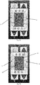
- the location of the brushes in the brush section 1 is shown in Figure 34 .
- Example 1B Four side brushes, static, horizontal
- a brush section 1 of a tunnel washing line 0 for crates 3 was built.
- the brushes were made with a steel cylindrical heart with a diameter of 35 mm, a nylon coating with an outer diameter of 100 mm and bristles of uncoloured nylon with a circular cross-section with a diameter of 0.5 mm.
- the brushes were placed opposite each other, i.e., two left side brushes and two right side brushes, the axes of rotation of the left side brushes 5 lying in one plane and the axes of rotation of the right side brushes 6 lying in one plane, and the left and right side planes perpendicular to the plane of conveyor 2 and located above the plane of conveyor 2.
- the distance between the left and right side plane was 500 mm, i.e., the setting for washing crates 3 with a width/length of 400 mm and a 50 mm overlap with the left and right side brushes.
- the distance between the centres of the left side brushes 5 on the left side plane was 190 mm, i.e., the adjacent brushes overlapped by 10 mm.
- the right side brushes 6 were placed at the same distance.
- the brushes were connected to the drive and were rotatable in the range of 1 to 800 revolutions per minute.
- the crate 3 wipes on the left and right horizontal rotating brushes, thereby achieving contact washing of the crate 3 and the efficiency of removing the labels on the crates 3 glued to the side plates of the crate 3 from the outside reaches up to 65 per cent.
- a brush section 1 of a tunnel washing line 0 for crates 3 was built.
- eight side brushes of circular cross-section with a height of half of the working wash zone, i.e., 160 mm, with a diameter of 160 mm were installed in the main wash section.
- the brushes were placed in the bottom part of the working wash zone to be able to wash by contact the sides of the passing crates 3 , especially in their bottom part, where labels are usually placed.
- the brushes were made with a steel cylindrical heart with a diameter of 25 mm, a nylon coating with an outer diameter of 80 mm and bristles of uncoloured nylon with a circular cross-section with a diameter of 1 mm.
- left side brushes 5 were placed on the left side line a
- four right side brushes 6 were placed on the right side line b.
- the right and left side lines were parallel to the axis h of the conveyor 2 feed.
- the left side brushes 5 were placed relative to the right side brushes 6 with a displacement along the left side line a of 8 cm, i.e., 1 ⁇ 2 r.
- the distance between the left and right side lines was 530 mm, i.e., the setting for washing crates 3 with a width/length of 400 mm and a 10mm overlap with the left and right side brushes.
- the distance between the centres of the left side brushes 5 on the left side line a was 120 mm, i.e., the adjacent brushes overlapped by 1 ⁇ 2r.
- the right side brushes 6 were placed at the same distance.
- the steel hearts of the brushes were led out through the ceiling of the working wash zone of the brush section 1 , where it was connected to the gears and belts connected to the drive.
- the drive was provided by an electric motor and the brushes were rotatable in the range of 1 to 3,000 revolutions per minute.
- the brush drive is switched on and set to 800 revolutions of brush per minute.
- the crate 3 is wiped with rotating left and right side brushes, thus achieving contact washing of the crate 3 and the efficiency of removing the labels on the crates 3 glued to the side plates of the crate 3 from the outside reaches up to 75 %.
- the location of brushes in the brush section 1 is shown in Figure 35 .
- a brush section 1 of a tunnel washing line 0 for crates 3 was built.
- twelve side brushes of circular cross-section with a height corresponding to the height of the working wash zone, i.e., 620 mm, with a diameter of 80 mm, were installed in the main wash section.
- the brushes were placed on the sides of the working wash zone to be able to wash by contact the sides of the passing crates 3 , where labels are usually placed.
- the brushes were made with a steel cylindrical heart with a diameter of 15 mm, a nylon coating with an outer diameter of 35 mm and bristles of uncoloured nylon with a circular cross-section with a diameter of 0.3 mm.
- left side brushes 5 were placed on the left side line a
- four right side brushes 6 were placed on the right side line b.
- the right and left side lines were parallel to the axis h of the conveyor 2 feed.
- the left side brushes 5 were located opposite the right side brushes 6 with a displacement along the left side line a by 1 ⁇ 2r, i.e. the centre of the first left side brush 5 was located in one axis centred between the first right and second right side brush 6, this axis being perpendicular to the axis h of the conveyor 2 feed.
- the distance between the left and right side lines was 560 mm, i.e., the setting for washing crates 3 with a width/length of 400 mm without an overlap.
- the distance between the centres of the left side brushes 5 on the left side line a was 100 mm, i.e. the adjacent brushes did not touch each other.
- the right side brushes 6 were placed at the same distance.
- the steel hearts of the brushes were led out through the ceiling of the working wash zone of the brush section, where they were connected to gears and belts connected to the drive.
- the brushes were rotatable in the range of 1 to 3,000 revolutions per minute.
- the brushes were made with a steel cylindrical heart with a diameter of 25 mm, a nylon coating with an outer diameter of 80 mm and bristles of uncoloured nylon with a circular cross-section with a diameter of 2 mm.
- Four left inner brushes 13 were placed on the left inner line c
- four right inner brushes 14 were placed on the right inner line d .
- the right and left inner lines c, d were parallel to the axis h of the conveyor 2 feed and were located between the left and right side lines a, b.
- the distance between the left and right inner lines c , d was 270 mm, i.e., the setting for washing crates 3 with a width/length of 400 mm and a 15mm overlap with the left and right inner brush 13, 14.
- the distance between the centres of the left inner brushes 13 on the left inner line c was 160 mm, i.e., the adjacent brushes touched only at one point.
- the right inner brushes 14 were placed at the same distance.
- the left inner brushes 13 were located opposite the right inner brushes 14, i.e., the centre of the first left inner brush 13 was located in one axis with the centre of the first right inner brush 14, this axis being perpendicular to the axis of the conveyor feed.
- the steel hearts of the brushes were led out through the ceiling of the working wash zone of the brush section, where they were connected to the gears and belts connected to the drive.
- the drive was provided by an electric motor and the brushes were rotatable in the range of 1 to 3,000 revolutions per minute.
- the brush section was fitted with a reversible lifting mechanism 7 comprising a piston-operated lifting plate 11 and one reversible last.
- the lifting plate 11 was placed on the conveyor 2, in the middle of the brush section 1 and served to lift the crate 3 into the brushes.
- the reversible last was attached to the ceiling of the working wash zone and pointed downwards.
- the reversible last was positioned in the place of the bottom of the crate 3 to be washed and was immersed in the upper brushes.
- the reversible last was mounted on a spring. The reversible last ensured the return of the lifted crate 3 to its initial position on the conveyor 2.
- the drive of the brushes is switched on and set to 1,000 revolutions of brush per minute.
- the crate 3 is wiped with the rotating left and right side brushes 5, 6, whereby a contact washing of the crate 3 is achieved.
- the passing crate 3 is gripped by the lifting fixators 9 and lifted towards the brushes, thereby coming into contact with the reversible last, which travels together with the crate 3 upwards into the upper brushes.
- the crate 3 is actively pushed downwards by the reversible last and guided by the lifting fixators 9 to its initial position on the conveyor 2, which takes out the crate 3 from the brush section 1 .
- the efficiency of removing the labels on the crates 3 glued to the side plates of the crate 3 from the outside and inside reaches up to 85 per cent.
- the location of the brushes in the brush section 1 is shown in Figure 36 .
- Example 4 Eight side rotating brushes, eight upper rotating brushes, three front rotating brushes and three rear rotating brushes
- a brush section 1 of a tunnel washing line 0 for crates 3 was built.
- eight side brushes of circular cross-section with a height corresponding to the height of the working wash zone, i.e., 620 mm, with a diameter of 160 mm, were installed in the main wash section.
- the brushes were placed on the sides of the working wash zone to be able to wash by contact the sides of the passing crates 3, where labels are usually placed.
- the brushes were made with a steel cylindrical heart with a diameter of 25 mm, a nylon coating with an outer diameter of 80 mm and bristles of uncoloured nylon with a circular cross-section with a diameter of 2 mm.
- the four left side brushes 5 were placed on the left side line a, the four right side brushes 6 were placed on the right side line b.
- the right and left side lines a, b were parallel to the axis h of the conveyor 2 feed.
- the left side brushes 5 were placed between the right side brushes 6, i.e., the centre of the first left side brush 5 was in one axis with the centre between the first and second right side brush 6, this axis being perpendicular to the axis h of the conveyor 2 feed.
- the distance between the left and right side lines a, b was 530 mm, i.e., the setting for washing crates 3 with a width/length of 400 mm and a 10 mm overlap with the left and right inner side 5, 6.
- the distance between the centres of the left side brushes 5 on the left side line a was 150 mm, i.e., the adjacent brushes have a 10 mm overlap.
- the right side brushes 6 were placed at the same distance.
- the steel hearts of the brushes were led out through the ceiling of the working wash zone of the brush section 1, where they were connected to the gears and belts connected to the drive.
- the drive was provided by an electric motor and the brushes were rotatable in the range of 1 to 3,000 revolutions per minute.
- the brushes were placed on the ceiling of the working wash zone so as to allow the passage of the washed crate 3 below them and to be able to wash by contact the inner space of the crate 3 lifted up by the reversible lifting mechanism 7.
- the brushes were made with a steel cylindrical heart with a diameter of 25 mm, a nylon coating with an outer diameter of 80 mm and bristles of uncoloured nylon with a circular cross-section with a diameter of 2 mm.
- the right and left inner lines c , d were parallel to the axis h of the conveyor 2 feed and were located between the left and right side lines a, b.
- the distance between the left and right inner lines c, d was 260 mm, i.e., the setting for washing crates 3 with a width/length of 400 mm and a 10mm overlap with the left and right inner brush 13, 14.
- the left inner brushes 13 were placed between the right inner brushes 14, i.e., the centre of the first left inner brush 13 was in one axis with the centre between the first and second right inner brush 14, this axis being perpendicular to the axis h of the conveyor 2 feed.
- the distance between the centres of the left inner brushes 13 on the left inner line c was 150 mm, i.e., the adjacent brushes have a 10 mm overlap.
- the right inner brushes 14 were placed at the same distance.
- the steel hearts of the brushes were led out through the ceiling of the working wash zone of the brush section 1, where they were connected to the gears and belts connected to the drive.
- the drive was provided by an electric motor and the brushes were rotatable in the range of 1 to 3,000 revolutions per minute.
- the brushes were placed on the ceiling of the working wash zone so as to allow the passage of the washed crate 3 below them and to be able to wash by contact from the outside the front and rear side plates of the crate 3 lifted up by the reversible lifting mechanism 7.
- the brushes were made with a steel cylindrical heart with a diameter of 25 mm, a nylon coating with an outer diameter of 80 mm and bristles of uncoloured nylon with a circular cross-section with a diameter of 2 mm.
- Three front brushes 15 were placed on the front line e, three rear brushes 16 were placed on the rear line f.
- the front and rear lines e, f were perpendicular to the axis h of the conveyor 2 feed and the front and rear brushes 15, 16 were located between the left and right side lines a, b.
- the distance between the front and rear lines e, f was 740 mm, i.e. the setting for washing crates 3 with a width/length of 600 mm and a 10mm overlap with front and rear brush 15, 16.
- the front brushes 15 were placed between the rear brushes 16, i.e., the centre of the first front brush 15 was in one axis with the centre between the first and second rear brush 16, this axis being perpendicular to the axis of the conveyor feed.
- the distance between the centres of the front brushes 15 on the front line e was 150 mm, i.e., the adjacent brushes have a 10mm overlap.
- the rear brushes 16 were placed at the same distance.
- the steel hearts of the brushes were led out through the ceiling of the working wash zone of the brush section 1, where they were connected to the gears and belts connected to the drive.
- the drive was provided by an electric motor and the brushes were rotatable in the range of 1 to 3,000 revolutions per minute
- the brush section was fitted with a reversible lifting mechanism 7 comprising two lifting fixators 9 and four eversible forks.
- the lifting fixators 9 were placed on the conveyor, in the middle of the brush section 1 and served to grip the bottom edge of the crate 3 and lift it up into the brushes.
- Four reversible forks were mounted in the ceiling of the working wash zone and pointed downwards.
- the reversible forks were positioned in the place of the front and rear side plates of the crate 3 to be washed and were immersed in the upper brushes.
- the reversible forks were movable up and down, operated by a drive.
- the reversible forks ensured the return of the lifted-up crate 3 to its initial position on the conveyor 2, and at the same time their shape prevented the folding of the side plates of the crate 3 and thus the deformation of the crate 3.
- the drive of the brushes is switched on and set to 1,200 revolutions of brush per minute.
- the crate 3 is wiped with the rotating left and right side brushes 5, 6, whereby a contact washing of the crate 3 is achieved.
- the passing crate 3 is gripped by the lifting fixators 9 and lifted towards the brushes, thereby coming into contact with the reversible forks, which secure the crate 3 against folding and travel together with the crate 3 up into the upper brushes.
- the crate 3 is actively pushed downwards by the reversible forks and guided by the lifting fixators 9 to its initial position on the conveyor 2, which takes out the crate 3 from the brush section 1 .
- the efficiency of removing the labels on the crates 3 glued to the side plates of the crate 3 from the outside and inside reaches up to 99 per cent.
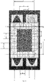
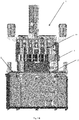
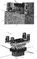
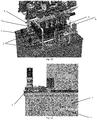
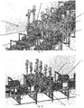
- the position of the brushes in the brush section 1 is shown in Figures 24 and 25 .
- the crate 3 with a label comes from the customer.
- the customer's requirement is that after washing, only the bottom layer of the sticker can remain on the crate, i.e., essentially only a 2x2 cm glue. This is an acceptable result of washing, in which case after washing, the crate with such 'residue' is further operated as clean.
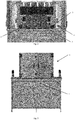
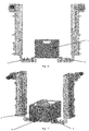
- the crate 3 travels to the classic high-pressure industrial tunnel washing line for washing. After washing, a large amount of paper sticker remained on the crate, see Figure 33 , more than the acceptable amount of 2x2 cm glue. In such a case, the crate 3 is excluded from the conventional washing process and travels to be 're-washed' to the desired state into the brush section 1 , which guarantees the removal of the remnants of the sticker from the crate 3.
- the soiled crate 3 was taken bottom down by the conveyor to the brush section 1 according to Example 4, where it was gripped by the lifting fixators 9 and lifted into brushes rotating around their axes at a speed of 800 revolutions per minute.
- the crate was secured with four reversible forks located in the place of the side plates of the crate, one fork for each side plate. After 1 s in the upper position, i.e., in contact with the brushes, the crate 3 was pushed out of the brushes by the reversible forks, back onto the conveyor 2 and the lifting fixators 9 moved away from the crate.
- the crate 3 was lifted into the brushes only once; in cases of extreme soiling the crate 3 can be lifted into the brushes several times, or the speed of rotation of the brushes can be increased or direction of their rotation can be changed. At the same time, it is possible to extend the contact of the crate 3 with the brushes or increase the speed of lifting the crate 3 into the brushes and returning the crate 3 onto the conveyor 2. After releasing the lifting fixators, the crate was collected again by the conveyor 2 and taken out of the brush section 1 . The time the crate 3 passed through the brush section 1 was 2 s. After passing through the brush section 1 , the crate 3 was thoroughly washed, see Figure 35 .
Landscapes
- Engineering & Computer Science (AREA)
- Mechanical Engineering (AREA)
- Cleaning In General (AREA)
Applications Claiming Priority (1)
| Application Number | Priority Date | Filing Date | Title |
|---|---|---|---|
| CZ2020-399A CZ2020399A3 (cs) | 2020-07-08 | 2020-07-08 | Kartáčová sekce tunelových mycích linek pro umytí přepravek od štítků |
Publications (1)
| Publication Number | Publication Date |
|---|---|
| EP3936244A1 true EP3936244A1 (fr) | 2022-01-12 |
Family
ID=77494948
Family Applications (1)
| Application Number | Title | Priority Date | Filing Date |
|---|---|---|---|
| EP21183069.0A Withdrawn EP3936244A1 (fr) | 2020-07-08 | 2021-07-01 | Section de brosses d'un tunnel de ligne de lavage pour éliminer les étiquettes des caisses |
Country Status (2)
| Country | Link |
|---|---|
| EP (1) | EP3936244A1 (fr) |
| CZ (1) | CZ2020399A3 (fr) |
Cited By (2)
| Publication number | Priority date | Publication date | Assignee | Title |
|---|---|---|---|---|
| CN114986905A (zh) * | 2022-07-22 | 2022-09-02 | 山东脉和增材制造有限公司 | 一种3d打印机及其控制方法 |
| CN119327770A (zh) * | 2024-10-21 | 2025-01-21 | 浙江工业大学 | 一种基于传感器与机器视觉的全自动反馈活塞清洗装置 |
Citations (8)
| Publication number | Priority date | Publication date | Assignee | Title |
|---|---|---|---|---|
| US1883772A (en) | 1930-04-12 | 1932-10-18 | John W Engholm | Washing and scrubbing apparatus for cases and boxes |
| JPS54139269A (en) | 1978-04-20 | 1979-10-29 | Tarutani Housou Sangiyou Kk | Washer of goodssdelivery box in plastic |
| EP0847813A1 (fr) * | 1996-12-16 | 1998-06-17 | Bastiaan Naaktgeboren | Dispositif et procédé pour nettoyer des conteneurs tels que des caisses agricoles par exemple |
| DE20021637U1 (de) | 2000-12-20 | 2001-03-22 | Paulus, Gerhard, 73230 Kirchheim | Bürstenstation für die Reinigung von Kunststoffkisten |
| JP2001232308A (ja) | 2000-02-23 | 2001-08-28 | Fine Machine Kataoka Kk | ワーク洗浄装置と、ワークの洗浄システム |
| WO2005028130A1 (fr) | 2003-09-22 | 2005-03-31 | Asahi Breweries, Ltd. | Procede de traitement de boite metallique et appareil de traitement de boite metallique faisant appel audit procede |
| CN208261460U (zh) | 2018-01-18 | 2018-12-21 | 惠州双叶华森包装设备有限公司 | 直线式桶装水桶外刷清洗机 |
| CN208357415U (zh) | 2018-05-06 | 2019-01-11 | 良基(厦门)自动化设备有限公司 | 一种周转箱立体清洗机 |
-
2020
- 2020-07-08 CZ CZ2020-399A patent/CZ2020399A3/cs unknown
-
2021
- 2021-07-01 EP EP21183069.0A patent/EP3936244A1/fr not_active Withdrawn
Patent Citations (8)
| Publication number | Priority date | Publication date | Assignee | Title |
|---|---|---|---|---|
| US1883772A (en) | 1930-04-12 | 1932-10-18 | John W Engholm | Washing and scrubbing apparatus for cases and boxes |
| JPS54139269A (en) | 1978-04-20 | 1979-10-29 | Tarutani Housou Sangiyou Kk | Washer of goodssdelivery box in plastic |
| EP0847813A1 (fr) * | 1996-12-16 | 1998-06-17 | Bastiaan Naaktgeboren | Dispositif et procédé pour nettoyer des conteneurs tels que des caisses agricoles par exemple |
| JP2001232308A (ja) | 2000-02-23 | 2001-08-28 | Fine Machine Kataoka Kk | ワーク洗浄装置と、ワークの洗浄システム |
| DE20021637U1 (de) | 2000-12-20 | 2001-03-22 | Paulus, Gerhard, 73230 Kirchheim | Bürstenstation für die Reinigung von Kunststoffkisten |
| WO2005028130A1 (fr) | 2003-09-22 | 2005-03-31 | Asahi Breweries, Ltd. | Procede de traitement de boite metallique et appareil de traitement de boite metallique faisant appel audit procede |
| CN208261460U (zh) | 2018-01-18 | 2018-12-21 | 惠州双叶华森包装设备有限公司 | 直线式桶装水桶外刷清洗机 |
| CN208357415U (zh) | 2018-05-06 | 2019-01-11 | 良基(厦门)自动化设备有限公司 | 一种周转箱立体清洗机 |
Cited By (3)
| Publication number | Priority date | Publication date | Assignee | Title |
|---|---|---|---|---|
| CN114986905A (zh) * | 2022-07-22 | 2022-09-02 | 山东脉和增材制造有限公司 | 一种3d打印机及其控制方法 |
| CN114986905B (zh) * | 2022-07-22 | 2024-05-10 | 山东脉和增材制造有限公司 | 一种3d打印机及其控制方法 |
| CN119327770A (zh) * | 2024-10-21 | 2025-01-21 | 浙江工业大学 | 一种基于传感器与机器视觉的全自动反馈活塞清洗装置 |
Also Published As
| Publication number | Publication date |
|---|---|
| CZ308923B6 (cs) | 2021-09-01 |
| CZ2020399A3 (cs) | 2021-09-01 |
Similar Documents
| Publication | Publication Date | Title |
|---|---|---|
| EP3936244A1 (fr) | Section de brosses d'un tunnel de ligne de lavage pour éliminer les étiquettes des caisses | |
| EP2727660A1 (fr) | Unité de traitement de récipients et procédé pour la reconfiguration d'une unité de traitement de récipients | |
| US6321761B1 (en) | Apparatus for holding down bottles in a high pressure wash | |
| US11969768B2 (en) | Washer peeler cleaning system | |
| KR20110045419A (ko) | 복식형 테이블 산업용 세척기 | |
| KR102285280B1 (ko) | 식기 세척기용 식기 이송장치 | |
| KR101224776B1 (ko) | 통과식 복식형 테이블 산업용 세척기 | |
| US6507969B2 (en) | Machine for washing containers | |
| CN210456389U (zh) | 一种网带机构自动清洗装置 | |
| US3079936A (en) | Bottle washing equipment | |
| US1421055A (en) | Washing machine | |
| GB2126566A (en) | A machine for cleaning receptacles | |
| CN213582360U (zh) | 一种通过传送带将动能转化成弹簧出货的货架结构 | |
| CN108672338A (zh) | 一种玻璃板材表面清理装置 | |
| JP2000167504A (ja) | 容器のラベル剥離装置 | |
| CN216073032U (zh) | 一种液体护肤品批量灌装装置 | |
| CN220825162U (zh) | 一种蛋托盘自动清洗装置 | |
| US885912A (en) | Bottle-handling apparatus. | |
| CN213613189U (zh) | 一种桶装水桶高压外洗装置 | |
| KR200395992Y1 (ko) | 과일세척장치 | |
| CN216403834U (zh) | 一种瓶口自动擦拭装置 | |
| JPH07214025A (ja) | 容器の自動洗浄方法と装置及び洗浄装置 | |
| KR200395991Y1 (ko) | 과일세척장치 | |
| CN210907298U (zh) | 喷洗机 | |
| US688740A (en) | Bottle washing and sterilizing machine. |
Legal Events
| Date | Code | Title | Description |
|---|---|---|---|
| PUAI | Public reference made under article 153(3) epc to a published international application that has entered the european phase |
Free format text: ORIGINAL CODE: 0009012 |
|
| STAA | Information on the status of an ep patent application or granted ep patent |
Free format text: STATUS: REQUEST FOR EXAMINATION WAS MADE |
|
| 17P | Request for examination filed |
Effective date: 20210716 |
|
| AK | Designated contracting states |
Kind code of ref document: A1 Designated state(s): AL AT BE BG CH CY CZ DE DK EE ES FI FR GB GR HR HU IE IS IT LI LT LU LV MC MK MT NL NO PL PT RO RS SE SI SK SM TR |
|
| B565 | Issuance of search results under rule 164(2) epc |
Effective date: 20211122 |
|
| STAA | Information on the status of an ep patent application or granted ep patent |
Free format text: STATUS: EXAMINATION IS IN PROGRESS |
|
| 17Q | First examination report despatched |
Effective date: 20231002 |
|
| STAA | Information on the status of an ep patent application or granted ep patent |
Free format text: STATUS: THE APPLICATION IS DEEMED TO BE WITHDRAWN |
|
| 18D | Application deemed to be withdrawn |
Effective date: 20240213 |