EP3936253A1 - Dispositif de retenue de plaque, dispositif d'extraction de plaque, dispositif de montage de plaque et dispositif de fixation/détachement de plaque - Google Patents
Dispositif de retenue de plaque, dispositif d'extraction de plaque, dispositif de montage de plaque et dispositif de fixation/détachement de plaque Download PDFInfo
- Publication number
- EP3936253A1 EP3936253A1 EP20766314.7A EP20766314A EP3936253A1 EP 3936253 A1 EP3936253 A1 EP 3936253A1 EP 20766314 A EP20766314 A EP 20766314A EP 3936253 A1 EP3936253 A1 EP 3936253A1
- Authority
- EP
- European Patent Office
- Prior art keywords
- plate
- metal frame
- holding device
- robot arm
- pressing
- Prior art date
- Legal status (The legal status is an assumption and is not a legal conclusion. Google has not performed a legal analysis and makes no representation as to the accuracy of the status listed.)
- Granted
Links
Images


Classifications
-
- B—PERFORMING OPERATIONS; TRANSPORTING
- B22—CASTING; POWDER METALLURGY
- B22D—CASTING OF METALS; CASTING OF OTHER SUBSTANCES BY THE SAME PROCESSES OR DEVICES
- B22D41/00—Casting melt-holding vessels, e.g. ladles, tundishes, cups or the like
- B22D41/14—Closures
- B22D41/22—Closures sliding-gate type, i.e. having a fixed plate and a movable plate in sliding contact with each other for selective registry of their openings
- B22D41/24—Closures sliding-gate type, i.e. having a fixed plate and a movable plate in sliding contact with each other for selective registry of their openings characterised by a rectilinearly movable plate
-
- B—PERFORMING OPERATIONS; TRANSPORTING
- B22—CASTING; POWDER METALLURGY
- B22D—CASTING OF METALS; CASTING OF OTHER SUBSTANCES BY THE SAME PROCESSES OR DEVICES
- B22D41/00—Casting melt-holding vessels, e.g. ladles, tundishes, cups or the like
- B22D41/14—Closures
- B22D41/22—Closures sliding-gate type, i.e. having a fixed plate and a movable plate in sliding contact with each other for selective registry of their openings
- B22D41/28—Plates therefor
- B22D41/34—Supporting, fixing or centering means therefor
-
- B—PERFORMING OPERATIONS; TRANSPORTING
- B22—CASTING; POWDER METALLURGY
- B22D—CASTING OF METALS; CASTING OF OTHER SUBSTANCES BY THE SAME PROCESSES OR DEVICES
- B22D41/00—Casting melt-holding vessels, e.g. ladles, tundishes, cups or the like
- B22D41/14—Closures
- B22D41/22—Closures sliding-gate type, i.e. having a fixed plate and a movable plate in sliding contact with each other for selective registry of their openings
- B22D41/28—Plates therefor
- B22D41/30—Manufacturing or repairing thereof
-
- B—PERFORMING OPERATIONS; TRANSPORTING
- B25—HAND TOOLS; PORTABLE POWER-DRIVEN TOOLS; MANIPULATORS
- B25J—MANIPULATORS; CHAMBERS PROVIDED WITH MANIPULATION DEVICES
- B25J9/00—Program-controlled manipulators
- B25J9/16—Program controls
- B25J9/1679—Program controls characterised by the tasks executed
- B25J9/1687—Assembly, peg and hole, palletising, straight line, weaving pattern movement
-
- G—PHYSICS
- G05—CONTROLLING; REGULATING
- G05B—CONTROL OR REGULATING SYSTEMS IN GENERAL; FUNCTIONAL ELEMENTS OF SUCH SYSTEMS; MONITORING OR TESTING ARRANGEMENTS FOR SUCH SYSTEMS OR ELEMENTS
- G05B2219/00—Program-control systems
- G05B2219/30—Nc systems
- G05B2219/37—Measurements
- G05B2219/37405—Contact detection between workpiece and tool, probe, feeler
-
- G—PHYSICS
- G05—CONTROLLING; REGULATING
- G05B—CONTROL OR REGULATING SYSTEMS IN GENERAL; FUNCTIONAL ELEMENTS OF SUCH SYSTEMS; MONITORING OR TESTING ARRANGEMENTS FOR SUCH SYSTEMS OR ELEMENTS
- G05B2219/00—Program-control systems
- G05B2219/30—Nc systems
- G05B2219/39—Robotics, robotics to robotics hand
- G05B2219/39529—Force, torque sensor in wrist, end effector
-
- G—PHYSICS
- G05—CONTROLLING; REGULATING
- G05B—CONTROL OR REGULATING SYSTEMS IN GENERAL; FUNCTIONAL ELEMENTS OF SUCH SYSTEMS; MONITORING OR TESTING ARRANGEMENTS FOR SUCH SYSTEMS OR ELEMENTS
- G05B2219/00—Program-control systems
- G05B2219/30—Nc systems
- G05B2219/40—Robotics, robotics mapping to robotics vision
- G05B2219/40032—Peg and hole insertion, mating and joining, remote center compliance
Definitions
- Plate holding device plate detaching apparatus, plate attaching apparatus, and plate attaching-detaching apparatus
- the present invention relates to a plate holding device for holding a plate for a sliding nozzle device, and a plate detaching apparatus, a plate attaching apparatus and a plate attaching-detaching apparatus each equipped with the plate holding device.
- a sliding nozzle device for use in continuous casting of molten steel employs two or three refractory plates, each of which is attached to a respective one of two or three plate-receiving metal frames.
- these plates reach the end of their life due to wear damage, it is necessary to open the sliding nozzle device to take out the old plates from respective plate-receiving metal frames, and replace the old plates with new ones.
- This replacement operation imposes a heavy burden on an operator, because it has to be performed under high temperature, and the weight of the plate, particularly heavy ones, is close to 30 kg.
- Patent Document 1 a plate holding device capable of holding a plate in a state in which it is mounted to a balancer or a robot arm, and a plate attaching method using the plate holding device.
- the plate holding device 1 comprises: a parallel gripper (parallel hand) 3 serving as widening and narrowing means; a pair of (two) holding members 4 each attached to a respective one of two parallel claws 31 of the parallel gripper 3; and a pressing unit 5 provided in front of the parallel gripper 3.
- each of the holding members 4 has two lateral arm portions, wherein an engagement groove 41 is formed at a distal end of each of the lateral arm portions.
- a plate 2 to be held by this plate holding device comprises: a plate body; a metal back plate 203 on the back side of the plate body; a metal band 205 covering a side (peripheral) surface of the plate body; and two plate-shaped fixable portions 209 each extending outwardly from a respective one of longitudinal opposite ends of the back plate 203.
- the plate is provided with a plate-shaped engagement protrusion 210 extending from the back plate 203 to serve as a to-be-held portion, by a number of two on one side, i.e., by a number of four in total.
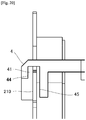
- the pair of holding members 4 are configured to be moved closer to and away from each other in the longitudinal direction (sliding direction) of the plate 2, according to movement of the parallel gripper 3, and to, when they hold the plate 2, ensure a certain gap between each of the engagement protrusions 210 and a contactable area which is an inner wall surface of a corresponding one of the engagement grooves 41, as shown in FIGS. 19 and 20 .
- a gap between the engagement protrusion 210 and a longitudinal-directional contactable area 42 of the engagement groove 41 (a gap in the longitudinal direction of the plate), a gap between the engagement protrusion 210 and a width-directional contactable area 43 of the engagement groove 41 (a gap in a width direction of the plate), and a gap between the engagement protrusion 210 and a thickness-directional contactable area 44 (45) of the engagement groove 41 (a gap in a thickness direction of the plate), are provided, wherein each of the gaps is set to 5 mm on one side.
- the plate 2 can move in any direction (in any of the longitudinal, width and thickness directions of the plate) within the range of a corresponding one of the gaps.
- the plate 2 is attached to a plate-receiving metal frame 6 of a sliding nozzle device in a state as shown in FIG. 21 .
- the holding members 4 of the plate holding device are inserted into a gap between the plate 2 and the plate-receiving metal frame 6 to perform the plate detaching operation.
- the sliding nozzle device is attached to the bottom of a molten steel pot.
- the plate assembled to the sliding nozzle device has to be detached from the side of the bottom of the molten steel pot in a state in which the molten steel pot is laid down.
- the molten steel pot is laid down by manipulating a crane.
- the crane is manually manipulated, the laid-down position of the molten steel pot will vary each time.
- the position of the sliding nozzle device has to be accurately measured each time.
- measurement of the position of an object during use of the robot arm has been commonly performed, using of a technique of acquiring an image of the object by a camera, and subjecting the acquired image to image processing, thereby correcting positional coordinates of the object.
- the sliding nozzle device it has been found that, in the image processing, there is a problem that a measurement accuracy in a front-rear direction (distance) becomes poor, although measurement accuracies in an up-down direction and in a right-left direction are at a practical level.
- the sliding nozzle device since the sliding nozzle device is used under a very severe condition that it receives radiation heat of molten steel having a temperature of 1500°C or more, while holding the plates through which the high-temperature molten steel passes, and is exposed to splash of the molten steel, and dust, the conventional position measurement technique has a problem of poor measurement accuracy in distance.
- the plate-receiving metal frame 6 disclosed in the Patent Document 1 comprises two guide protrusions 61 each for guiding a respective one of the two fixable portions 209 of the plate.
- Each of the guide protrusions 61 of the plate-receiving metal frame 6 has a base end-side portion formed in a columnar shape, and a distal end-side portion formed in a truncated cone shape.
- the plate 2 When attaching the plate 2 to the plate-receiving metal frame 6, the plate 2 is inserted into the plate-receiving metal frame 6, such that respective openings 209a of the fixable portions 209 provided at the longitudinal opposite ends of the plate 2 are moved, respectively, along the guide protrusions 61 of the plate-receiving metal frame 6, so that the longitudinal and widthwise positions of the plate 2 will be guided to accurate positions, with respect to the plate-receiving metal frame 6.
- the plate 2 attached to the plate-receiving metal frame 6 is held by lock mechanisms 7 so as to prevent dropping from the plate-receiving metal frame 6.
- the present inventors attempted to, under the condition that the sliding nozzle device was used in an iron foundry, and the plate holding device 1 disclosed in the Patent Document 1 was mounted to an articulated robot arm, attach the plate to the plate-receiving metal frame of the sliding nozzle device using the plate holding device 1.
- a gap arises between the plate and a bottom surface of the plate-receiving metal frame, and thereby holding of the plate by the lock mechanisms becomes insufficient, in some cases.
- Such a gap does not cause any problem as long as it is not excessively large, because the gap will disappear or become vanishingly small when the plate-receiving metal frame is closed to apply a surface pressure between the plates.
- the plate fails to be firmly fixed to the plate-receiving metal frame, resulting in dropping or displacement during use, or a problem that, in a case where the plate is an upper plate, a joint thickness on a bonding surface of the upper plate with the upper nozzle increases.
- the displacement of the plate during use or the increase in the thickness of the joint can lead to a risk of leakage of molten steel during use.
- the plate holding device disclosed in the Patent Document 1 can also be used to hold the plate so as to perform the plate attaching or detaching operation, in a state in which the bolts are loosened.
- the plate when fittingly attaching a new plate to the plate-receiving metal frame, the plate is fittingly attached to a receiving portion of the plate-receiving metal frame while being pressed by a robot arm.
- the plate is not fitted into the receiving portion, and thereby a problem in fittingly attaching the plate arises, in some cases.
- a problem to be solved by the present invention is to provide a plate holding device, a plate detaching apparatus, a plate attaching apparatus and a plate attaching-detaching apparatus which are capable of reliably attaching and/or detaching a plate with respect to a plate-receiving metal frame.
- a plate can be reliably attached/detached with respect to a plate-receiving metal frame by: providing a pressing unit for pressing a central region of the plate when the plate is held by holding members of a plate holding device, and/or a force sensor for detecting a force received by the holding members from the held plate; and operating (widening/narrowing) the holding members of the plate holding device when the force detected by the force sensor reaches a given threshold.
- a plate can be reliably attached at a given position of the plate-receiving metal frame by modifying the operation of pressing the plate held by the plate holding device in a direction toward the plate-receiving metal frame, to a two-stage pressing operation consisting of a first-stage pressing operation to be performed in a state in which the plate is held by the holding members, and a second-stage pressing operation to be performed without holding the plate by the holding members.
- a plate holding device a plate detaching apparatus, a plate attaching apparatus and a plate attaching-detaching apparatus, as described in the following sections 1 to 17.
- a plate holding device configured to be mounted to a distal end of a robot arm so as to selectively attach and detach a plate with respect to a plate-receiving metal frame of a sliding nozzle device, wherein the plate-receiving metal frame is composed of a fixed metal frame, or a swingable metal frame openable and closable with respect to the fixed metal frame, wherein the plate holding device comprises: a holding member for holding the plate; and a pressing mechanism for inhibiting the swingable metal frame from being swung in a closing direction.
- a plate holding device configured to be mounted to a distal end of a robot arm so as to selectively attach and detach a plate with respect to a plate-receiving metal frame of a sliding nozzle device, wherein plate holding device comprises: a holding member for holding the plate; and a vibration unit for applying vibration to the held plate.
- the present invention makes it possible to reliably attach and/or detach a plate with respect to the plate-receiving metal frame.
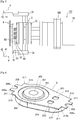
- FIG. 1 is a side view of the plate holding device 101 in a state in which it holds a plate 2 (wherein only the after-mentioned holding members 4 are shown in cross-section).
- the plate holding device 101 illustrated in FIG. 1 is obtained by modifying the plate holding device 1 disclosed in the Patent Document 1 as shown in FIGS. 17 and 18 , such that the pressing unit 5 is changed to a pressing unit 9 having no coil springs, and a force sensor 10 is provided on the side opposite to the pressing unit 9 with respect to a parallel gripper (parallel hand) 3 serving as widening and narrowing means.
- the pressing unit 9 comprises a support plate 91 which is attached to a gripper body 32 of the parallel gripper 3 by bolts 93.
- a pressing plate 92 is fixed to the support plate 91, so that the support plate 91 and the pressing plate 92 are integrated together.
- This pressing plate 92 is set at a position which allows four engagement grooves 41 in a pair of (two) holding members 4 each attached to a respective one of two parallel claws 31 of the parallel gripper 3 and four engagement protrusions 210 of the plate 2 to be engaged with each other, when the pressing plate 92 presses a central region of the plate 2.
- the pressing unit 9 (pressing plate 92) is disposed at a position which allows the pressing unit 9 to press the central region of the plate 2 when the plate 2 is held by the pair of holding members 4.
- the pair of holding members 4 can be moved to narrow a distance therebetween so as to hold the plate 2.
- the widening and narrowing means is not limited to the parallel gripper 3.
- a parallel chuck may be used.
- it may be composed using a hydraulic cylinder, an air cylinder or the like.
- the widening and narrowing means is not necessarily limited to the configuration in which the pair of holding members 4 are selectively widened and narrowed while maintaining a parallel relationship therebetween.
- it may be configured such that a distance between the distal ends of the pair of holding members 4 are selectively widened and narrowed by swinging movements of the pair of holding members 4 about respective base ends (intersection point) thereof.
- the force sensor 10 is attached, by bolts, to a flange 102 on the side opposite to the pressing unit 9 with respect to the gripper body 32 of the parallel gripper 3. That is, the force sensor 10 is a sensor configured to detect a force received by the holding members 4 and/or the pressing unit 9 from the held plate 2. Such a force sensor to detect a force is also referred to as "haptic sensor", and a type of haptic sensor commonly used in robot arms or the like may be employed. In this embodiment, a six-axis force sensor is used as the force sensor 10.
- FIG. 2 A plate detaching apparatus equipped with the plate holding device 101 is shown in FIG. 2 .
- a ladle 11 just after completion of casting is laid down on a ladle support 13 installed on a floor 12.
- a sliding nozzle device 14 is attached to the bottom 111 of the ladle 11.
- a robot arm 15 is installed such that a base end thereof is fixed to a robot arm mount (illustration is omitted) provided on the floor 12, and a flange of the force sensor 10 of the plate holding device 101 is mounted to a distal end of the robot arm 15 by bolts.
- the force sensor 10 and the distal end of the robot arm 15 are arranged in series, such that central axes thereof are aligned with each other.
- the robot arm 15 is a 6-axis vertical articulated robot arm, and capable of freely changing the posture and position of the plate holding device 101 mounted to the distal end thereof.
- a three-dimensional sensor 16 comprising a camera 16a and a laser irradiator 16b is attached around the distal end of the robot arm 15.
- An image acquired by the camera 16a is input to an image processing device, and, in the image processing device, three-dimensional positional coordinates are corrected by an image processing process.
- the resulting coordinate information is input to a control unit 17, so that it becomes possible to controllably operate the robot arm 15 so as to move the plate holding device 101 to a position where the plate holding device 101 can hold the plate 2.
- information detected by the force sensor 10 is continuously input in the control unit 17. Then, the control unit 17 controls movement of the plate holding device 101, based on the information from the force sensor 10, etc.
- an image of a plate-receiving metal frame 6 of the sliding nozzle device 14 is acquired by the camera 16a, while laser light is emitted from the laser irradiator 16b toward two image-acquisition reference areas (markers) provided, respectively, at an upper end and a lower end of the plate-receiving metal frame 6, and the resulting image is subjected to image processing, thereby computing a misalignment of the plate-receiving metal frame 6 with respect to a reference position and correcting three-dimensional positional coordinates of the plate-receiving metal frame 6.
- This corrected position of the plate-receiving metal frame 6 is input to the control unit 17, so that the robot arm 15 is operated to move the plate holding device 101 mounted to the robot arm 15 to the corrected position.
- the holding members 4 of the plate holding device is spaced apart from the plate 2 and the plate-receiving metal frame 6 to avoid contact therewith.
- the above corrected position is set to a position just before a position where the plate 2 received in the plate-receiving metal frame 6 is to be held by the holding members 4 of the plate holding device, e.g., by about 1 cm.
- control unit 17 is operable to controllably operate the robot arm 15 so as to move the plate holding device 101 to the above corrected position, and, after stopping the plate holding device 101 at the corrected position once, further moving the plate holding device 101 toward the plate 2 received in the plate-receiving metal plate 6.
- the pressing unit 9 of the plate holding device is brought into contact with the plate 2.
- the holding members 4 and/or the pressing unit 9 receive a force as a reaction force from the plate 2, and this force is detected by the force sensor 10.
- the control unit 17 is operable to, when the force detected by the force sensor 10 reaches a given threshold (e.g., 300 N), controllably operate the robot arm 15 so as to stop the movement of the plate holding device 101, and controllably operate the parallel gripper 3 so as to narrow a distance between the pair of holding members 4, thereby holding the plate 2.
- a given threshold e.g. 300 N
- the control unit 17 is operable to controllably operate the robot arm 15 so as to move the plate holding device 101 backwardly, thereby detaching the plate 2 from the plate-receiving metal frame 6.
- the plate detaching apparatus is configured to stop the plate holding device 101 at the aforementioned corrected position once. However, the stop at the corrected position may be omitted.
- the plate detaching apparatus is configured such that, when the force detected by the force sensor 10 reaches the given threshold, the holding members 4 align with respective to-be-held portions (engagement protrusions 210) of the plate.
- the plate detaching apparatus in the first embodiment can be used as a plate attaching apparatus.
- the control unit 17 may be configured to: controllably operate the robot arm 15 so as to move a plate 2 held by the plate holding device 101 toward the plate-receiving metal frame 6; and, then when the force detected by the force sensor 10 reaches a given threshold (e.g., 500N), controllably operate the robot arm 15 so as to stop the movement of the plate holding device 101, and controllably operate the parallel gripper 3 so as to widen the distance between the holding members 4 to release the plate 2, thereby attaching the plate 2 to the plate-receiving metal frame 6.
- a given threshold e.g. 500N
- FIG. 3 is a side view of the plate holding device 101 in a state in which it holds a plate 2 (wherein only the after-mentioned holding members 4 are shown in cross-section).
- the plate holding device 101 illustrated in FIG. 3 is obtained by modifying the pressing unit 9 of the plate holding device 101 according to the first embodiment illustrated in FIG. 1 , to a pressing unit 9 having coil springs as with the Patent Document 1.
- a pressing unit 9 having coil springs as with the Patent Document 1.
- four coil springs are used, whereas, in the second embodiment, seven coil springs 94 are used in the pressing unit 9.
- seven bolts 93 are fixed to a base plate 95 while penetrating through seven through-holes of a support plate 91 and the seven coil springs 94, as shown in FIG. 3 .
- This base plate 95 is attached to a gripper body 32 of a parallel gripper (parallel hand) 3.
- a pressing plate 92 is fixed to the support plate 91, so that the support plate 91 and the pressing plate 92 are integrated together.
- the pressing plate 92 can be moved toward the base plate 95 while compressing the coil springs 94.
- a certain gap may be provided between each of the through-holes of the support plate 91 and a corresponding one of the bolts 93.
- the pressing plate 92 can be moved even when it is in a tilted state.
- the pressing plate 92 is set at a position where the coil springs 94 are compressed when the plate 2 is held by holding members 4 (engagement grooves 41) of the plate holding device 101. Therefore, the plate is pressed against a plate-receiving metal frame-side region of an inner wall surface of each of the engagement grooves 41.
- the plate holding device 101 having the pressing unit 9 with the coil springs also comprises a force sensor 10 like that in the plate holding device 101 according to the first embodiment, so that it is possible to obtain the same functions/effects as those of the plate holding device 101 according to the first embodiment.
- the plate holding device 101 according to the second embodiment may be mounted to the distal end of the robot arm 15 as shown in FIG. 2 , to provide a plate detaching apparatus or a plate attaching apparatus.
- FIG. 4 A usage state of a plate attaching apparatus according to a third embodiment of the present invention is shown in FIG. 4 . Further, a plate holding device used in the plate attaching apparatus illustrated in FIG. 4 is shown in FIG. 5 .
- This plate holding device 101 is obtained by modifying the plate holding device 1 disclosed in the Patent Document 1 as shown in FIG. 17 , such that the pressing unit 5 is changed to a pressing unit 9, and a force sensor 10 is provided on the side opposite to the pressing unit 9 with respect to a parallel gripper (parallel hand) 3 serving as widening and narrowing means.
- the plate holding device 101 comprises: a parallel gripper (parallel hand) 3 serving as widening and narrowing means; a pair of (two) holding members 4 each attached to a respective one of parallel claws 31 of the parallel gripper 3; and a pressing unit 9 provided in front of a gripper body 32 of the parallel gripper 3, and a force sensor 10 provided on the side opposite to the pressing portion 9 with respect to the parallel gripper 3.
- each of the holding members 4 has two lateral arm portions, wherein an engagement groove 41 is formed at a distal end of each of the lateral arm portions.
- the plate holding device 101 is configured such that, when holding a plate, a gap of 5 mm is ensured between each of the after-mentioned engagement protrusions 210 and an inner wall surface of a corresponding one of the engagement grooves 41.
- the plate can move in any direction (in any of longitudinal, width and thickness directions of the plate) within the range of the gap.
- the widening and narrowing means is not limited to the parallel gripper 3.
- a parallel chuck may be used.
- it may be composed using a hydraulic cylinder, an air cylinder or the like.
- the widening and narrowing means is not necessarily limited to the configuration in which the pair of holding members 4 are selectively widened and narrowed while maintaining a parallel relationship therebetween.
- it may be configured such that a distance between the distal ends of the pair of holding members 4 are selectively widened and narrowed by swinging movements of the pair of holding members 4 about respective base ends (intersection point) thereof.
- the pressing unit 9 has a similar structure to that of the pressing unit 5 of the plate holding device 1 disclosed in the Patent Document 1 as shown in FIG. 17 .
- the Patent Document 1 four coil springs are used, whereas, in the third embodiment, seven coil springs are used in the pressing unit 9.
- seven bolts 93 are fixed to a base plate 95 while penetrating through seven through-holes of a support plate 91 and the seven coil springs 94, as shown in FIG. 5 .
- This base plate 95 is attached to the gripper body 32 of the parallel gripper 3.
- a pressing plate 92 is fixed to the support plate 91, so that the support plate 91 and the pressing plate 92 are integrated together.
- the pressing plate 92 can be moved toward the base plate 95 while compressing the coil springs 94.
- a certain gap may be provided between each of the through-holes of the support plate 91 and a corresponding one of the bolts 93. In this case, the pressing plate 92 can be moved even when it is in a tilted state.
- the pressing plate 92 is set at a position where the coil springs 94 are compressed when the plate is held by the holding members 4 (engagement grooves 41). Therefore, the plate is pressed against a plate-receiving metal frame-side region of an inner wall surface of each of the engagement grooves 41.
- the force sensor 10 is attached, by bolts, to a flange 102 on the side opposite to the pressing unit 9 with respect to the gripper body 32 of the parallel gripper 3. That is, the force sensor 10 is a sensor configured to detect a force received by the holding members 4 and/or the pressing unit 9 from the held plate 2. Such a force sensor to detect a force is also referred to as "haptic sensor", and a type of haptic sensor commonly used in robot arms or the like may be employed. In the third embodiment, a six-axis force sensor is used as the force sensor 10.
- the plate 2 having the same configuration as that in the Patent Document 1 is used.
- the plate 2 comprises: a refractory plate body 201; a metal back plate 203 on the back side of the plate body; a metal band 205 covering a side (peripheral) surface of the plate body; and two plate-shaped fixable portions 209 each extending outwardly from a respective one of longitudinal opposite ends of the back plate 203.
- the back plate 203 also has an engagement protrusion 210 by a number of two at each of longitudinal opposite ends thereof, i.e., by a number of four in total.
- the back plate 203 has two fitting recesses 212 configured to fittingly receive two fitting protrusions (not illustrated) provided on a plate-receiving metal frame, respectively, thereby preventing displacement of the plate even when a force is applied to the plate in a sliding direction of the plate.
- FIG. 4 a ladle 11 just after completion of casting is laid down on a ladle support 13 installed on a floor 12.
- a sliding nozzle device 14 is attached to the bottom 111 of this ladle, and, in the posture illustrated in FIG. 4 , the sliding direction is approximately aligned with a vertical direction.
- This sliding nozzle device 14 is placed in a state in which a sliding metal frame 142, i.e., a plate-receiving metal frame for a lower plate, is opened with respect to a fixed metal frame 141, i.e., a plate-receiving metal frame for an upper plate, wherein the upper plate and the lower plate are detached, respectively, from the fixed metal frame 141 and the sliding metal frame 142.
- a sliding metal frame 142 i.e., a plate-receiving metal frame for a lower plate
- a robot arm 15 is installed such that a base end thereof is fixed to a robot arm mount (illustration is omitted) provided on the floor 12, and a flange of the force sensor 10 of the plate holding device 101 is mounted to a distal end of the robot arm 15 by bolts.
- the force sensor 10 and the distal end of the robot arm 15 are arranged in series, such that central axes thereof are aligned with each other.
- the robot arm 15 is a 6-axis vertical articulated robot arm, and capable of freely changing the posture and position of the plate holding device 101 mounted to the distal end thereof.
- a three-dimensional sensor 16 comprising a camera 16a and a laser irradiator 16b is attached around the distal end of the robot arm 15.
- An image acquired by the camera 16a is input to an image processing device, and, in the image processing device, three-dimensional positional coordinates are corrected by an image processing process.
- the resulting coordinate information is input to a control unit 17, so that it becomes possible to controllably operate the robot arm 15 so as to move the plate holding device 101 to a plate attaching position.
- information detected by the force sensor 10 is continuously input in the control unit 17. Then, the control unit 17 controls movement of the plate holding device 101, based on the information from the force sensor 10, etc.
- FIGS. 7a to 7d show an example where the plate 2 held by the plate holding device 101 is moved closer to a bottom surface 143 of the fixed metal frame 141, in a tilted posture, instead of a vertical posture.
- the plate attaching apparatus is capable of attaching a plate to each of the fixed metal frame 141 which is the plate-receiving metal frame for the upper plate and the sliding metal frame 142 as the plate-receiving metal frame for the lower plate, the following description will be made about only a method of attaching the upper plate to the fixed metal frame 141. Further, since the upper plate and the lower plate have the same configuration, the upper plate will also be referred to simply as "plate" in the following description.
- an image of the fixed metal frame 141 of the sliding nozzle device 14 from which a used plate is detached is acquired by the camera 16a, while laser light is emitted from the laser irradiator 16b toward the fixed metal frame 141, and the resulting image is subjected to image processing, thereby computing a misalignment of the fixed metal frame 141 with respect to a reference position and correcting three-dimensional positional coordinates of the fixed metal frame 141.
- This corrected position of the fixed metal frame 141 is input to the control unit 17, so that the robot arm 15 is operated to move the plate holding device 101 mounted to the robot arm 15 to the corrected position (the state illustrated in FIG. 7a ).
- the above corrected position is set to a position just before a given position of the fixed metal frame 141 in which the plate is to be received, e.g., by about 1 cm.
- the fixed metal frame 141 comprises two lock mechanisms 7 each for holding a respective one of the two fixable portions 209 at the upper and lower ends of the plate 2, and two guide protrusions 61 each fittable in a respective one of respective openings 209a (see FIG. 6 ) of the fixable portions 209 to position the plate 2.
- Each of the guide protrusions 61 is structurally the same as that disclosed in the Patent Document 1.
- each of the lock mechanisms 7 is different from that in the Patent Document 1, in terms of an installation position thereof on the bottom surface 143 of the fixed metal frame 141, but structurally the same as that in the Patent Document 1.
- each of the lock mechanisms 7 comprises a holding block 71 movable in a direction parallel to the sliding direction of the plate via a spring (illustration is omitted).
- the holding block 71 moves in a direction away from the plate. Then when the fixable portion 209 of the plate contacts a second inclined surface 73, the holding block 71 slightly moves toward the plate to lock the fixable portion 209 of the plate.
- the bottom surface 143 of the fixed metal frame 141 has two recesses 62 each provided at a position corresponding to a respective one of the holding members 4 of the plate holding device 101 to allow the distal end of the holding member 4 to intrude therein.
- Each of the recesses 62 is set to a size which allows the distance between the holding members 4 of the plate holding device 101 to be widened and narrowed in a state in which the back plate 203 of the plate contacts the bottom surface 143 of the fixed metal frame 141.
- the upper plate Since mortar is used as a joint material between the upper plate and an upper nozzle, the upper plate is held by the plate holding device in a state in which mortar is applied onto the upper plate. Specifically, in FIG. 6 , mortar is applied onto a raised portion 207 of the plate body 210 in an opening 204 of the back plate 203, and around the raised portion 207.
- the plate holding device 101 is moved toward the fixed metal frame 141, and each of the openings of the fixable portions 209 starts to be engaged with a respective one of the guide protrusions 61 of the fixed metal frame 141. From this state, the plate 2 is gradually moved toward the bottom surface 143 of the fixed metal frame 141 while being positionally adjusted between two sets of the engagement grooves 41 of the holding members 4 of the plate holding device 101 and the guide protrusions 61.
- each of the upper engagement protrusions 210 of the plate contacts a base end-side inner wall surface of a corresponding one of the engagement grooves 41 of the upper holding member 4 of the plate holding device 101, and an upper portion of the back plate 203 of the plate contacts the bottom surface 143 of the fixed metal frame 141.
- the fixable portions 209 have not yet be completely locked by the lock mechanisms 7.
- the mortar between the plate 2 and the upper nozzle has not yet become a desired joint thickness. In this state, the upper holding member 4 cannot be moved toward the bottom surface 143 of the fixed metal frame 141 any more, and thereby a large reaction force is generated. Thus, the force detected by the force sensor 10 reaches the given threshold A.
- the movement of the plate holding device 101 is stopped once, and the distance between the holding members 4 of the plate holding device 101 is widened to release the plate 2, as shown in FIG. 7c .
- the engagement protrusions 210 of the plate become free from engagement with the holding members, and thereby the force detected by the force sensor 10 decreases.
- the plate holding device 101 is further moved toward the fixed metal frame 141, the plate can be pressed against the bottom surface 143 of the fixed metal frame 141 only by the pressing unit 9. In this process, the pressing unit 9 can be tilted in any direction via the coil springs 94.
- the back plate 203 of the plate 2 is placed in a posture parallel to the bottom surface 143 of the fixed metal frame 141, and the fixable portions 209 of the plate 2 are locked by the lock mechanisms 7. Further, although not illustrated, the fitting recesses of the plate fittingly receive the fitting protrusions provided on the plate-receiving metal frame.
- the plate holding device 101 is further moved toward the fixed metal frame 141 to press the plate against the bottom surface 143 of the fixed metal frame 141 only by the pressing unit 9, the force detected by the force sensor 10 starts to increase. Then, when this force reaches a given threshold B, the movement of the plate holding device 101 is stopped. Subsequently, the plate holding device 101 is moved in a direction away from the fixed metal frame 141, while leaving the plate in the fixed metal frame 141. In this way, the plate 2 is attached to the fixed metal frame 141.
- the distance between the holding members 4 widened during releasing of the plate is preferably set to allow the engagement protrusions 210 of the plate 2 to completely get out of the engagement grooves 41 of the holding members 4 of the plate holding device 101, as shown in FIG. 7c .
- a distance between respective inner surfaces 42 of the holding members in a widening and narrowing direction as shown in FIG. 5 may be set to be greater than a distance between respective outer surfaces 210a of the opposite engagement protrusions 210 in the sliding direction of the plate as shown in FIG. 6 .
- a gap is provided between each of the engagement grooves 41 of the holding members 4 and a corresponding one of the engagement protrusions 210 of the plate 2.
- the distance between the inner surfaces 42 of the holding members 4 in the widening and narrowing direction may be set to be greater than a sum of the distance between the outer surfaces 210a of the opposite engagement protrusions in the sliding direction of the plate and the length of the gap.
- the gap between each of the engagement grooves 41 of the holding members 4 and a corresponding one of the engagement protrusions 210 of the plate 2 is initially set to 5 mm on one side. Therefore, the distance between the inner surfaces 42 of the holding members 4 of the plate holding device 101 in the widening and narrowing direction may be set to be greater than 310 mm obtained by adding 10 mm which is the gap on both sides to 300 mm which is the distance between the outer surfaces 210a of the opposite engagement protrusions in the sliding direction of the plate. In the third embodiment, it is set to 350 mm.
- this distance may be set to a value to the extent that can avoid such a contact.
- the aforementioned threshold A of the force detected by the force sensor is determined depending on use conditions, because it depends on the size of the plate, whether or not mortar is used, or the hardness of mortar when it is used. If the threshold A is excessively small, the plate is likely to drop when the distance between the holding members is widened to release the plate. Although there is no particular problem with setting the threshold A to a fairly large value, it is necessary to increase the strength of the plate and the plate holding device, resulting in an increase in unprofitable cost. For example, there is no problem with setting the threshold A such that the entire back plate 203 of the plate becomes a state in which it fully contacts the bottom surface 143 of the fixed metal frame 141, at the time when a force equal to the threshold A is measured.
- the threshold A is preferably set such that the plate is moved toward the bottom surface of the fixed metal frame 141 until it is engaged with the guide protrusions 61 or the lock mechanisms 7 to some extent so as not to drop.
- the threshold A may be adequately set in the range of 50 N to 3000 N.
- the aforementioned threshold B of the forth detected by the force sensor is set to be equal to or greater than the threshold A set such that the plate becomes a state in which it is locked by the lock mechanisms so as not to drop.
- FIG. 8 is an explanatory diagram showing a usage state of a plate attaching-detaching apparatus according to a fourth embodiment of the present invention.
- the plate attaching-detaching apparatus 1A is obtained by mounting a plate holding device 101A to a robot arm 15.
- This plate attaching-detaching apparatus 1A is configured to selectively attach and detach a plate 2 with respect to a plate-receiving metal frame assembly 6A of a sliding nozzle device 14A provided on, e.g., the bottom 111 of a ladle 11.
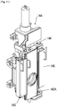
- FIG. 9 is a perspective view of the plate holding device 101A in the fourth embodiment.
- the plate holding device 101A in the fourth embodiment comprises a pressing mechanism 18 and a vibration mechanism 19.
- the configuration of the plate holding device 101A in the fourth embodiment is the same as that of the plate holding device 101 in the third embodiment, except for the pressing mechanism 18 and the vibration mechanism 19, and therefore description of the common configuration will be omitted.
- FIGS. 10 and 11 are perspective view of the sliding nozzle device 14A.
- the sliding nozzle device 14A comprises the plate-receiving metal frame assembly 6A and a spring box 145.
- the plate-receiving metal frame assembly 6A comprises a fixed metal frame 141A and a swingable metal frame 142A, in each of which a plate (not illustrated) is received.
- the swingable metal frame 142A is provided such that it is swung about a pivot shaft 144 with respect to the fixed metal frame 141A in an openable closable manner.
- the swingable metal frame 142A in the fourth embodiment is slidably provided with respect to the fixed metal frame 141A. That is, the swingable metal frame 142A in the fourth embodiment is equivalent to a sliding metal frame (the sliding metal frame 142 in the third embodiment).
- a plate replacement operation is performed in a state in which the swingable metal frame 142A is opened with respect to the fixed metal frame 141A.
- the swingable metal frame 142A may be configured to be swingable in a closing direction, or a mechanism for fixing the swingable metal frame 142A immovably in the closing direction may be employed separately.
- the spring box 145 of the sliding nozzle device 14A is used to load a surface pressure to the plate-receiving metal frame assembly 6A during use of the sliding nozzle device 14Ato hold the plate-receiving metal frame assembly 6A in a closed state.
- Each of the fixed metal frame 141A and the swingable metal frame 142A has a receiving portion (1411, 1421) in which the plate is to be received, and an outer surface (1412, 1422) forming an outer shape of the metal frame. Further, each of the receiving portions 1411, 1421 is formed with two fitting protrusions 146 onto each of which a respective one of two fitting recesses 212 (see FIG. 18 ) of the plate 2 is to be fitted.
- the remaining configurations of the fixed metal frame 141A and the swingable metal frame 142A are the same as those of the fixed metal frame 141 and the sliding metal frame 142 in the third embodiment, and therefore description thereof will be omitted.
- the pressing mechanism 18 comprises a pressing mechanism body 18a, a moving part 18b coupled to the pressing mechanism body 18a, and a spherical-shaped contact part 18c provided at a distal end of the moving part 18b.
- the pressing mechanism 18 is provided on a mounting plate 33 extending downwardly from a gripper body 33 of the plate holding device 101A.
- the pressing mechanism 18 is disposed below a pair of holding members 4 by a number of two.
- the moving part 18b is provided such that it is extendable and retractable (movable forwardly and backwardly), with respect to an end of the pressing mechanism body 18a. Further, the moving part 18b is disposed to extend forwardly (in a direction toward the swingable metal frame) from the end of the pressing mechanism body 18a.
- the contact part 18c When the moving part 18b is retracted, the contact part 18c is disposed on the side of the gripper body 32 with respect to distal ends of the holding members 4.
- This arrangement makes it possible to prevent a situation where, when the holding members 4 are inserted into the swingable metal frame 142A, the contact part 18c is brought into contact with the swingable metal frame 42A before the holding members 4 reaches a region in which the plate is received. That is, the contact part 18c is disposed at a position where, when the holding members 4 are inserted into the swingable metal frame 142A, a gap is formed between the swingable metal frame and the contact part 18c, and thereby the contact part 18c does not become an obstacle to the insertion of the holding members 4.
- the moving part 18b may be configured to be extended such that the contact part 18c protrudes with respect to the distal ends of the holding members 4.
- the two pressing mechanisms 10 are provided at bilaterally symmetrical positions with respect to a vertical central axis of the plate holding device 101A.
- the pressing mechanism body 18a of the pressing mechanism 18 is internally provided with a drive mechanism such as an electromagnetic pneumatic valve or an electric motor.
- a drive mechanism such as an electromagnetic pneumatic valve or an electric motor.
- the moving part 18b can be controllably extended and retracted.
- a plate holding operation of the holding members of the plate holding device 101A and the movement of the robot arm can be interlocked with the extending and retracting operations of the moving part 18b.
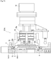
- the plate attaching-detaching apparatus 1A comprising the plate holding device 101A with the pressing mechanism 18 operates as follows.
- the robot arm 15 is operated to insert the holding members 4 of the plate holding device 101A into the plate receiving portion 1421 of the swingable metal frame 142A. Then, the holding members 4 of the plate holding device 101A are moved to hold the plate 2, as shown in FIG. 12 . Then, in a first mode, the moving part 18b is extended in a state in which the holding members 4 4 hold the plate 2, as shown in FIG. 13a . Thus, the contact part 18c presses a lower end region of the outer surface 1422 of the swingable metal frame 142A. In conjunction with the operation of extending the moving part 18b, the robot arm 15 is moved in a direction away from the swingable metal frame 142A. In this process, since swinging movemermt of the swingable metal frame 142Ain the closing direction is inhibited by the extended contact part 18c, the holding members 4 can be pulled out of the receiving portion 1421 of the swingable metal frame 142A.
- the moving part 18b continues to be extended to hold the state in which the contact part 18c contacts the outer surface 1422 of the swingable metal frame 142A. In this way, based on the operation of the robot arm 15, the holding members 4 of the plate holding device 101A are moved outside the receiving portion 1421 of the swingable metal frame 142A to detach the plate 2.
- the first mode illustrated in FIG. 13a is a mode in which the plate 2 is detached without tilting the swingable metal frame 142A.
- FIG. 13b it is possible to employ a second mode in which the lower end region of the outer surface 1422 of the swingable metal frame 142A is pressed by the pressing mechanism 18 so as to tilt the swingable metal frame 142A, thereby releasing a lower lock mechanism 7 of the swingable metal frame 142A, and disengaging the lower fixable portion 209 of the plate 2 from the swingable metal frame 142A.
- the moving part 18b is extended in the state in which the holding members 4 hold the plate 2, as shown in FIG. 13b .
- the contact part 18c presses the lower end region of the outer surface 1422 of the swingable metal frame 142A to release engagement between the lower fixable portion 209 of the plate 2 and the swingable metal frame 142A.
- the robot arm 15 is moved in the direction away from the swingable metal frame 142A to pull out the holding members 4 from the receiving portion 1421 of the swingable metal frame 142A.
- the moving part 18b continues to be extended to hold the state in which the contact part 18c contacts the outer surface 1422 of the swingable metal frame 142A. In this way, based on the operation of the robot arm 15, the holding members 4 of the plate holding device 101A are moved outside the receiving portion 1421 of the swingable metal frame 142A to detach the plate 2.
- the pressing mechanism 18 presses the lower end region of the outer surface 1422 of the swingable metal frame 142A.
- the pressed lower portion of the swingable metal frame 142A is moved rearwardly, so that the swingable metal frame 142A is leaned (tilted) frontwardly with respect to the holding members 4 of the plate holding device 101A.
- the lower fixable portion 209 of the plate 2 located on a second inclined surface 73 of the after-mentioned holding block 71 of the lower lock mechanism 7 is moved to a first inclined surface 72 of the holding block 71 over the second inclined surface 73. Therefore, the engagement between the lower fixable portion 209 of the plate 2 and the swingable metal frame 142A is released.
- the robot arm 15 is moved in a direction away from the receiving portion 1421 of the swingable metal frame 142A. In this way, it is possible to detach the plate from the swingable metal frame 142A.
- the swingable metal frame 142A is placed in a state in which the swinging movement thereof in the closing direction is inhibited to some extent by the contact part 18c, and the swinging movement of the swingable metal frame 142A in the closing direction is inhibited by the extended contact part 18a, so that it is possible to reliably detach the plate 2 from the swingable metal frame 142A by the robot arm 15.
- the robot arm 15 is moved in the direction away from the swingable metal frame 142A, thereby detaching the plate 2 from the swingable metal frame 142A.
- the holding members 4 of the plate holding device 101A may be configured to be movable forwardly and backwardly with respect to the swingable metal frame 142A, wherein the plate 2 may be detached from the swingable metal frame 142A by moving the holding members 4 in the direction away from the receiving portion 1421 of the swingable metal frame 142A.
- the operation of extending the moving part 18b and the operation of moving the robot arm 15 in the direction away from the swingable metal frame 142A are simultaneously performed.
- the plate attaching-detaching apparatus may be configured such that only the moving part 18b is first extended, and, after the contact part 18c is brought into contact with the swingable metal frame 142A, the robot arm 15 is moved in the direction away from the swingable metal frame 142A.
- the pressing mechanism 18 in the fourth embodiment may be configured to perform control of opening the swingable metal frame 142A to a given position. In this case, in a situation where the swingable metal frame 142A is not located at the given position when the swingable metal frame 142A is opened, the pressing mechanism 18 can press the swingable metal frame 142A so as to swingingly move the swingable metal frame 142A to the given position.
- the pressing mechanism 18 is provided below the holding members 4 in the plate holding device 101A.
- the pressing mechanism 18 may be provided above the holding members 4 or provided beside (on the right or left side of) the holding members 4, as long as it is configured to be capable of pressing the swingable metal frame 142A.
- the two pressing mechanisms 18 are provided only below the holding members 4.
- the pressing mechanism 18 may be provided both above and below the holding members 4, or may be provided below and beside, or above and beside, or above, below and beside the holding members 4, respectively.
- the pressing mechanism 18 is preferably configured to press one of opposite ends of the swingable metal frame 142A corresponding to the lock mechanisms 7.
- the pressing mechanism 18 is preferably configured to press one of the upper and lower ends of the swingable metal frame 142A so as to release the engagement between the plate 2 and the swingable metal frame 142A. Further, the two pressing mechanisms 18 are preferably provided at symmetrical positions with respect to the holding members 4. Although the pressing mechanism 18 is preferably provided by a number of two like the fourth embodiment, it may be provided by a number of only one or three or more.
- the contact part 18c is preferably formed in a spherical shape so as to cope with surface irregularity of the swingable metal frame 142A, it may take any of various other shapes such as a plate shape, a cubic shape or a rectangular parallelepiped shape.
- the moving part 18b is configured to be driven in an extendable and retractable manner.
- the moving part 18b may be configured to be biased using a spring or the like in a direction along with the moving part 18b is extended.
- the contact part 18c may be initially disposed to protrude with respect to the distal ends of the holding members 4.
- the contact part 18c can bias the swingable metal frame 142A in the open direction.
- the spring is contracted, the pressing mechanism 18 does not become an obstacle to the insertion of the holding members 4.
- each of the lock mechanisms 7 of the swingable metal frame 142A comprises a holding block 71 movable forwardly and backwardly with respect to the receiving portion 1421 of the swingable metal frame 142A, and a spring (not illustrated) biasing the holding block 71 toward the inward side of the swingable metal frame 142A.
- the plate holding device is configured such that, during the operation of detaching the plate 2, the pressing mechanism 18 contacts the outer surface 1422 of the swingable metal frame 142A. According to this configuration, the pressing mechanism 18 can press the swingable metal frame 142A in an immovable manner, thereby inhibiting the swingable metal frame 142A from following the movement of the robot arm 15.
- the pressing mechanism 18 is operated, in the second mode, to press the lower end region of the outer surface 1422 of the swingable metal frame 142A to tilt the swingable metal frame 142A, thereby releasing the lower lock mechanism 7 of the swingable metal frame 142A, and disengaging the lower fixable portion 209 of the plate 2 from the swingable metal frame 142A.
- the lock mechanisms 7 are partially released by the pressing mechanism 18, so that it becomes easier for the robot arm 15 to detach the plate 2.
- the plate 2 can also be detached from the swingable metal frame 142A without any problem, as mentioned above.
- the fourth embodiment has been described based on an example where the plate-receiving metal frame assembly is configured to receive two plates. However, there has also been known a plate-receiving metal frame assembly configured to receive three plates. In this case, the plate-receiving metal frame assembly comprises two swingable metal frames, wherein the pressing mechanism 18 in the fourth embodiment may be used when a plate is detached from each of these swingable metal frames.
- the plate holding device 101A is configured to hold a plate 2 comprising a back plate 203 disposed on a back surface of a plate body 201, and, in this state, selectively attach and detach the plate 2 with respect to the swingable metal frame.
- the plate holding device may be configured to hold a commonly-used plate devoid of the back plate as disclosed in the Patent Document 2, and in this state, selectively attach and detach the plate with respect to the swingable metal frame.
- vibration mechanism 19 (vibration unit) comprised in the plate holding device 101A will be described.
- the vibration mechanism 19 comprises a vibration mechanism body 19a provided on a lateral surface of the gripper body 32 of the plate holding device 101A, and a vibration applicator 19b provided at a distal end of the vibration mechanism 19a.
- the vibration mechanism 19 is provided by a number of two on the right and left sides of the holding members 4 of the plate holding device 101A.
- the vibration mechanism body 19a is internally provided with a vibrating device (not illustrated) such as a vibrating motor.
- the vibrating device is configured such that start and stop of vibration can be electrically controlled.
- the vibration mechanism body 19a is vibrated by vibrating the vibrating device.
- the vibration of the vibration mechanism body 19a is transmitted to the vibration applicator 19b.
- the vibration applicator 19b contacts a back surface of a pressing unit 9A, and is capable of transmitting vibration to the pressing unit 9A.
- a vibration direction of the vibration applicator 19b may be set to a direction horizontal to the pressing unit 9A.
- the vibration applicator 19b is likely to be displaced in the vibration direction, causing a change in position where vibration is transmitted to the pressing unit 9A. Therefore, the vibration direction is preferably set to a direction perpendicular to the pressing unit 9A.
- the vibration mechanism body 19a is vibrated when the pressing unit 9A of the plate holding device 101A presses the plate 2. This vibration is transmitted from the vibration applicator 19b to the plate 2 via the pressing unit 9A. In other words, the plate 2 can be vibrated by vibrating the vibration mechanism body 19a.
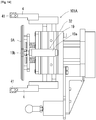
- the plate attaching-detaching apparatus 1A comprising the plate holding device 101A with the vibration mechanism 19 operates as follows.
- the holding members 4 of the plate holding device 101A are moved to hold the plate 2. Then, as shown in FIG. 15 , the robot arm 15 is operated to insert the holding members 4 holding the plate 2 into the receiving portion 1411 of the fixed metal frame 141A.
- the robot arm 15 is operated to insert the holding members 4 holding the plate 2 into the receiving portion 1411 of the fixed metal frame 141A.
- the operation of inserting the holding members 4 by the robot arm 15 is stopped. Then, a distance between the holding members 4 is widened to release the plate 2.
- the robot arm 15 is moved in a direction coming closer to the fixed metal frame 141A to press the plate 2 by the pressing unit 9A, and the vibration mechanism body 19a is vibrated. Then, as shown in FIG. 16 , when the fixable portions 209 of the plate 2 are locked by the after-mentioned lock mechanisms 7 of the fixed metal frame 141A, and the force detected by the force sensor 10 reaches a given threshold B, the vibration of the vibration mechanism body 19a is stopped.
- the vibration mechanism body 19a may continue to be vibrated for several seconds after the force detected by the force sensor 10 reaches the given threshold B. This makes it possible to more reliably lock the fixable portions 209 of the plate 2 by the lock mechanisms 7.
- the operation of inserting the holding members 4 by the robot arm 15 is stopped.
- a position toward which the holding members 4 should be moved to approach the fixed metal frame 141A may be preliminarily set, and the plate attaching-detaching apparatus may be configured such that, when the holding members 4 reach the preset position, the distance between the holding members 4 are widened to release the plate 2, and the pressing of the plate 2 by the robot arm 15 and the vibration of the vibration mechanism body 19a are started.
- the fourth embodiment has been described based on an example where the plate 2 is attached to the fixed metal frame 141A, it should be understood that the plate 2 can be attached to the swingable metal frame 142A in a similar manner.
- the holding members 4 are not positively vibrated. This is because, if the holding members 4 are vibrated during holding or insertion of the plate 2, the position of the plate 2 can become misaligned with respect to the receiving portion 1411, resulting in failing to adequately insert the plate 2.
- the vibration mechanism 19 (vibration unit) is provided separately from the holding members 4. Thus, even when the vibration mechanism 19 is vibrated, the holding members 4 are not vibrated.
- the vibration mechanism 19 is provided by a number of two on right and left lateral surfaces of the gripper body 32 of the plate holding device 101A.
- the two vibration mechanisms may be provided, respectively, on upper and lower lateral surfaces of the gripper body 32.
- the vibration mechanism 19 may be provided by a number of only one or may be provided by a number of three or more, as long as it is configured to evenly transfer vibration to the plate 2.
- the vibration applicator 19b may be provided with a vibrating device and configured to vibrate by itself.
- the vibration mechanism 19 may be used during detaching of the plate 2.
- substances adhered to the plate 2 such as iron, slag and mortar are solidified to cause difficulty in detaching the plate 2.
- the pressing unit 9A is brought into contact with the plate 2, and vibration is applied from the vibration mechanism 19 to the plate 2, thereby removing the adhered substances to facilitate detaching of the plate 2.
- the fixed metal frame 141A is provided with two lock mechanisms 7 for locking the plate 2.
- Each of the lock mechanisms 7 comprises a holding block 71 movable forwardly and backwardly with respect to the inside of the fixed metal frame 141A, and a spring (not illustrated) biasing the holding block 71 toward the inward side of the swingable metal frame 142A.
- the holding block has a first inclined surface 72 and a second inclined surface 73.
- the robot arm 15 When the plate 2 is fittingly attached to the fixed metal frame 141A, the robot arm 15 needs to be moved in a direction causing the plate 2 to be pressed against the holding blocks 71, in a state in which the fixable portions 209 of the plate 2 contact the first inclined surface 72 of the holding blocks 71. Through this operation, the fixable portions 209 of the plate 2 can be guided to the second inclined surface 73, while releasing the lock mechanisms 7 of the fixed metal frame 141A.
- the fixed metal frame 141A has fitting protrusions 146 corresponding to fitting recesses 212 of the plate 2.
- an attaching error of several mm arises in the operation of attaching the plate 2 by the robot arm 15, and thereby the fitting recesses 212 of the plate 2 fail to be fitted on the fitting protrusions 146 of the fixed metal frame 141A, in some cases.
- the above problems can be solved by vibrating the plate 2 using the vibration mechanism 19 to vibrationally move the plate 2 within the fixed metal frame 141A. More specifically, the plate 2 is vibrated during the operation of inserting the plate 2 into the fixed metal frame 141A, so that the plate 2 can be finely displaced, and thereby becomes more likely to contact the first inclined surfaces 72 of the holding blocks 71 and to be fitted into the side of the second inclined surface 73. Further, the plate 2 is vibrated when the plate 2 is brought into contact with the fixed metal frame 141A, so that the plate 2 can be finely displaced, and thereby the fitting recesses 212 thereof become more likely to be fitted on the fitting protrusions 146 of the fixed metal frame 141A.
- the plate 2 can be vibrated to fluidize the mortal, thereby preventing the mortar from becoming an obstacle to insertion of the plate 2 into the fixed metal frame 141A. Further, before inserting the plate 2 into the fixed metal frame 141A, the plate 2 can be vibrated to remove dust adhered thereto.
- the plate attaching-detaching apparatus 1A can also be used for attaching and detaching of a plate of a sliding nozzle device provided in a container for receiving molten steel, such as a tundish.
- the fourth embodiment has been described based on an example where a plate-receiving metal frame assembly is configured to receive two plates.
- the vibration mechanism 19 can also be used when a plate is inserted into a plate-receiving metal frame assembly configured to receive three plates.
Landscapes
- Engineering & Computer Science (AREA)
- Mechanical Engineering (AREA)
- Manufacturing & Machinery (AREA)
- Robotics (AREA)
- Manipulator (AREA)
Applications Claiming Priority (5)
| Application Number | Priority Date | Filing Date | Title |
|---|---|---|---|
| JP2019038779A JP7219637B2 (ja) | 2019-03-04 | 2019-03-04 | プレート取外装置及びプレート取付装置 |
| JP2019038784A JP7169229B2 (ja) | 2019-03-04 | 2019-03-04 | プレート取付装置 |
| JP2019113968A JP7219676B2 (ja) | 2019-06-19 | 2019-06-19 | プレート保持装置及びプレート着脱装置 |
| JP2019113970A JP7219677B2 (ja) | 2019-06-19 | 2019-06-19 | プレート着脱装置 |
| PCT/JP2020/008857 WO2020179774A1 (fr) | 2019-03-04 | 2020-03-03 | Dispositif de retenue de plaque, dispositif d'extraction de plaque, dispositif de montage de plaque et dispositif de fixation/détachement de plaque |
Publications (4)
| Publication Number | Publication Date |
|---|---|
| EP3936253A1 true EP3936253A1 (fr) | 2022-01-12 |
| EP3936253A4 EP3936253A4 (fr) | 2022-11-16 |
| EP3936253C0 EP3936253C0 (fr) | 2024-05-29 |
| EP3936253B1 EP3936253B1 (fr) | 2024-05-29 |
Family
ID=72338338
Family Applications (1)
| Application Number | Title | Priority Date | Filing Date |
|---|---|---|---|
| EP20766314.7A Active EP3936253B1 (fr) | 2019-03-04 | 2020-03-03 | Dispositif de fixation/détachement de plaque |
Country Status (5)
| Country | Link |
|---|---|
| US (1) | US11958106B2 (fr) |
| EP (1) | EP3936253B1 (fr) |
| CN (1) | CN113165059B (fr) |
| ES (1) | ES2981804T3 (fr) |
| WO (1) | WO2020179774A1 (fr) |
Cited By (1)
| Publication number | Priority date | Publication date | Assignee | Title |
|---|---|---|---|---|
| EP3950238A4 (fr) * | 2019-03-27 | 2022-12-21 | Krosakiharima Corporation | Dispositif pour ouverture/fermeture |
Families Citing this family (4)
| Publication number | Priority date | Publication date | Assignee | Title |
|---|---|---|---|---|
| JP7252992B2 (ja) * | 2021-02-04 | 2023-04-05 | 黒崎播磨株式会社 | 取付装置 |
| JP7249366B2 (ja) * | 2021-02-04 | 2023-03-30 | 黒崎播磨株式会社 | スライディングノズル装置 |
| CN115889706A (zh) * | 2021-09-30 | 2023-04-04 | 宝钢工程技术集团有限公司 | 基于传感器的连铸自动化浇铸装置及其使用方法 |
| JP2024174660A (ja) * | 2023-06-05 | 2024-12-17 | 黒崎播磨株式会社 | 下部ノズル着脱装置 |
Family Cites Families (20)
| Publication number | Priority date | Publication date | Assignee | Title |
|---|---|---|---|---|
| JPS4979325A (fr) * | 1972-12-06 | 1974-07-31 | ||
| JP2876725B2 (ja) * | 1990-07-02 | 1999-03-31 | 品川白煉瓦株式会社 | 溶融金属容器のスライドバルブの交換装置 |
| JPH06190542A (ja) * | 1992-12-28 | 1994-07-12 | Nippon Steel Corp | スライディングノズル耐火物保持用ハンド |
| JP2922765B2 (ja) * | 1993-11-09 | 1999-07-26 | 東芝セラミックス株式会社 | ロボットハンド及びそれによる耐火物プレートの脱着方法 |
| JP2983140B2 (ja) * | 1994-07-29 | 1999-11-29 | 品川白煉瓦株式会社 | 溶融金属容器用カートリッジ式スライディングバルブ装置のカートリッジハンドリング用ハンド |
| JP3147335B2 (ja) * | 1997-03-25 | 2001-03-19 | 東芝セラミックス株式会社 | 溶融金属収納鍋用耐火物交換装置 |
| JP3273427B2 (ja) * | 1997-05-27 | 2002-04-08 | 住友金属工業株式会社 | 溶融金属容器用耐火物の交換方法及び溶融金属容器用耐火物の交換装置 |
| JP3247941B2 (ja) * | 1997-10-31 | 2002-01-21 | 日本鋼管株式会社 | スライディングノズル用プレート |
| WO2005063424A1 (fr) * | 2003-12-25 | 2005-07-14 | Daishinkako Co., Ltd. | Instrument de mesure de degats causes a une plaque |
| EP1894649A1 (fr) * | 2006-09-01 | 2008-03-05 | Stopinc Aktiengesellschaft | Dispositif de maintenance d'un obturateur coulissant monté au trou d'un récipient contenant du métal liquide |
| JP2011104606A (ja) | 2009-11-13 | 2011-06-02 | Kurosaki Harima Corp | プレートれんがの固定機構 |
| JP5892459B2 (ja) * | 2011-08-25 | 2016-03-23 | 株式会社Ihi | 組立ロボットとその制御方法 |
| DE102012224343A1 (de) * | 2012-09-20 | 2014-03-20 | Sms Siemag Aktiengesellschaft | Vorrichtung zur Positionsbestimmung eines metallurgischen Gefäßes |
| CN202951872U (zh) * | 2012-10-19 | 2013-05-29 | 宝山钢铁股份有限公司 | 一种用于连铸中间包滑板的连接装置 |
| JP6270595B2 (ja) * | 2014-04-01 | 2018-01-31 | 鈴鹿エンヂニヤリング株式会社 | ベールゴムの吊り揚げ搬送方法及びその装置 |
| JP2016215249A (ja) * | 2015-05-22 | 2016-12-22 | 黒崎播磨株式会社 | 収納金枠へのプレートの装着方法 |
| JP6577841B2 (ja) | 2015-11-10 | 2019-09-18 | 黒崎播磨株式会社 | 浸漬ノズル |
| JP6600242B2 (ja) * | 2015-12-14 | 2019-10-30 | 黒崎播磨株式会社 | スライディングノズル装置 |
| JP6802033B2 (ja) | 2016-10-20 | 2020-12-16 | 黒崎播磨株式会社 | プレートの保持装置、保持構造及び保持方法 |
| CN108214535B (zh) * | 2017-12-29 | 2020-12-04 | 南京理工大学 | 一种同步控制机械手 |
-
2020
- 2020-03-03 WO PCT/JP2020/008857 patent/WO2020179774A1/fr not_active Ceased
- 2020-03-03 EP EP20766314.7A patent/EP3936253B1/fr active Active
- 2020-03-03 ES ES20766314T patent/ES2981804T3/es active Active
- 2020-03-03 US US17/432,193 patent/US11958106B2/en active Active
- 2020-03-03 CN CN202080005740.8A patent/CN113165059B/zh active Active
Cited By (1)
| Publication number | Priority date | Publication date | Assignee | Title |
|---|---|---|---|---|
| EP3950238A4 (fr) * | 2019-03-27 | 2022-12-21 | Krosakiharima Corporation | Dispositif pour ouverture/fermeture |
Also Published As
| Publication number | Publication date |
|---|---|
| WO2020179774A1 (fr) | 2020-09-10 |
| BR112021014036A2 (pt) | 2021-09-21 |
| CN113165059B (zh) | 2023-06-09 |
| US11958106B2 (en) | 2024-04-16 |
| EP3936253C0 (fr) | 2024-05-29 |
| US20220097129A1 (en) | 2022-03-31 |
| ES2981804T3 (es) | 2024-10-10 |
| EP3936253A4 (fr) | 2022-11-16 |
| CN113165059A (zh) | 2021-07-23 |
| EP3936253B1 (fr) | 2024-05-29 |
Similar Documents
| Publication | Publication Date | Title |
|---|---|---|
| EP3936253B1 (fr) | Dispositif de fixation/détachement de plaque | |
| EP3950238B1 (fr) | Dispositif pour ouverture/fermeture | |
| CA3039145C (fr) | Plaque, et dispositif de maintien de plaque et procede de maintien | |
| JP4160830B2 (ja) | スライディングノズル装置 | |
| JP7482877B2 (ja) | スライド式ゲートバルブプレートを交換するためのロボット化システム | |
| JP7219676B2 (ja) | プレート保持装置及びプレート着脱装置 | |
| JP7219677B2 (ja) | プレート着脱装置 | |
| JP7219637B2 (ja) | プレート取外装置及びプレート取付装置 | |
| JP7169229B2 (ja) | プレート取付装置 | |
| US20250296144A1 (en) | Sliding nozzle device mounting system | |
| RU2359772C2 (ru) | Крепление для устройства для выправки кузова автомобиля | |
| EP4289529B1 (fr) | Dispositif de buse coulissante | |
| BR112021014036B1 (pt) | Aparelho de remoção de placa, e, aparelho de afixação de placa | |
| CN116802001B (zh) | 使用安装装置安装驱动装置的系统 | |
| JP4095143B2 (ja) | スライディングノズル装置 |
Legal Events
| Date | Code | Title | Description |
|---|---|---|---|
| STAA | Information on the status of an ep patent application or granted ep patent |
Free format text: STATUS: THE INTERNATIONAL PUBLICATION HAS BEEN MADE |
|
| PUAI | Public reference made under article 153(3) epc to a published international application that has entered the european phase |
Free format text: ORIGINAL CODE: 0009012 |
|
| STAA | Information on the status of an ep patent application or granted ep patent |
Free format text: STATUS: REQUEST FOR EXAMINATION WAS MADE |
|
| 17P | Request for examination filed |
Effective date: 20210728 |
|
| AK | Designated contracting states |
Kind code of ref document: A1 Designated state(s): AL AT BE BG CH CY CZ DE DK EE ES FI FR GB GR HR HU IE IS IT LI LT LU LV MC MK MT NL NO PL PT RO RS SE SI SK SM TR |
|
| DAV | Request for validation of the european patent (deleted) | ||
| DAX | Request for extension of the european patent (deleted) | ||
| REG | Reference to a national code |
Ref legal event code: R079 Free format text: PREVIOUS MAIN CLASS: B22D0011100000 Ipc: B22D0041300000 Ref country code: DE Ref legal event code: R079 Ref document number: 602020031682 Country of ref document: DE Free format text: PREVIOUS MAIN CLASS: B22D0011100000 Ipc: B22D0041300000 |
|
| A4 | Supplementary search report drawn up and despatched |
Effective date: 20221017 |
|
| RIC1 | Information provided on ipc code assigned before grant |
Ipc: B25J 9/16 20060101ALI20221011BHEP Ipc: G05B 99/00 20060101ALI20221011BHEP Ipc: B22D 41/24 20060101ALI20221011BHEP Ipc: B22D 41/34 20060101ALI20221011BHEP Ipc: B22D 41/30 20060101AFI20221011BHEP |
|
| STAA | Information on the status of an ep patent application or granted ep patent |
Free format text: STATUS: EXAMINATION IS IN PROGRESS |
|
| 17Q | First examination report despatched |
Effective date: 20230627 |
|
| REG | Reference to a national code |
Ref country code: DE Free format text: PREVIOUS MAIN CLASS: B22D0041300000 Ref country code: DE Ref legal event code: R079 Ref document number: 602020031682 Country of ref document: DE Free format text: PREVIOUS MAIN CLASS: B22D0041300000 Ipc: B22D0041240000 |
|
| RIC1 | Information provided on ipc code assigned before grant |
Ipc: B25J 9/16 20060101ALI20231106BHEP Ipc: B22D 41/34 20060101ALI20231106BHEP Ipc: B22D 41/30 20060101ALI20231106BHEP Ipc: B22D 41/24 20060101AFI20231106BHEP |
|
| GRAP | Despatch of communication of intention to grant a patent |
Free format text: ORIGINAL CODE: EPIDOSNIGR1 |
|
| STAA | Information on the status of an ep patent application or granted ep patent |
Free format text: STATUS: GRANT OF PATENT IS INTENDED |
|
| INTG | Intention to grant announced |
Effective date: 20231221 |
|
| GRAS | Grant fee paid |
Free format text: ORIGINAL CODE: EPIDOSNIGR3 |
|
| GRAA | (expected) grant |
Free format text: ORIGINAL CODE: 0009210 |
|
| STAA | Information on the status of an ep patent application or granted ep patent |
Free format text: STATUS: THE PATENT HAS BEEN GRANTED |
|
| AK | Designated contracting states |
Kind code of ref document: B1 Designated state(s): AL AT BE BG CH CY CZ DE DK EE ES FI FR GB GR HR HU IE IS IT LI LT LU LV MC MK MT NL NO PL PT RO RS SE SI SK SM TR |
|
| REG | Reference to a national code |
Ref country code: CH Ref legal event code: EP |
|
| REG | Reference to a national code |
Ref country code: IE Ref legal event code: FG4D |
|
| REG | Reference to a national code |
Ref country code: DE Ref legal event code: R096 Ref document number: 602020031682 Country of ref document: DE |
|
| REG | Reference to a national code |
Ref country code: SK Ref legal event code: T3 Ref document number: E 44219 Country of ref document: SK |
|
| U01 | Request for unitary effect filed |
Effective date: 20240618 |
|
| U07 | Unitary effect registered |
Designated state(s): AT BE BG DE DK EE FI FR IT LT LU LV MT NL PT SE SI Effective date: 20240628 |
|
| PG25 | Lapsed in a contracting state [announced via postgrant information from national office to epo] |
Ref country code: IS Free format text: LAPSE BECAUSE OF FAILURE TO SUBMIT A TRANSLATION OF THE DESCRIPTION OR TO PAY THE FEE WITHIN THE PRESCRIBED TIME-LIMIT Effective date: 20240929 |
|
| PG25 | Lapsed in a contracting state [announced via postgrant information from national office to epo] |
Ref country code: HR Free format text: LAPSE BECAUSE OF FAILURE TO SUBMIT A TRANSLATION OF THE DESCRIPTION OR TO PAY THE FEE WITHIN THE PRESCRIBED TIME-LIMIT Effective date: 20240529 |
|
| REG | Reference to a national code |
Ref country code: ES Ref legal event code: FG2A Ref document number: 2981804 Country of ref document: ES Kind code of ref document: T3 Effective date: 20241010 |
|
| PG25 | Lapsed in a contracting state [announced via postgrant information from national office to epo] |
Ref country code: GR Free format text: LAPSE BECAUSE OF FAILURE TO SUBMIT A TRANSLATION OF THE DESCRIPTION OR TO PAY THE FEE WITHIN THE PRESCRIBED TIME-LIMIT Effective date: 20240830 |
|
| PG25 | Lapsed in a contracting state [announced via postgrant information from national office to epo] |
Ref country code: PL Free format text: LAPSE BECAUSE OF FAILURE TO SUBMIT A TRANSLATION OF THE DESCRIPTION OR TO PAY THE FEE WITHIN THE PRESCRIBED TIME-LIMIT Effective date: 20240529 |
|
| PG25 | Lapsed in a contracting state [announced via postgrant information from national office to epo] |
Ref country code: PL Free format text: LAPSE BECAUSE OF FAILURE TO SUBMIT A TRANSLATION OF THE DESCRIPTION OR TO PAY THE FEE WITHIN THE PRESCRIBED TIME-LIMIT Effective date: 20240529 Ref country code: NO Free format text: LAPSE BECAUSE OF FAILURE TO SUBMIT A TRANSLATION OF THE DESCRIPTION OR TO PAY THE FEE WITHIN THE PRESCRIBED TIME-LIMIT Effective date: 20240829 Ref country code: IS Free format text: LAPSE BECAUSE OF FAILURE TO SUBMIT A TRANSLATION OF THE DESCRIPTION OR TO PAY THE FEE WITHIN THE PRESCRIBED TIME-LIMIT Effective date: 20240929 Ref country code: HR Free format text: LAPSE BECAUSE OF FAILURE TO SUBMIT A TRANSLATION OF THE DESCRIPTION OR TO PAY THE FEE WITHIN THE PRESCRIBED TIME-LIMIT Effective date: 20240529 Ref country code: GR Free format text: LAPSE BECAUSE OF FAILURE TO SUBMIT A TRANSLATION OF THE DESCRIPTION OR TO PAY THE FEE WITHIN THE PRESCRIBED TIME-LIMIT Effective date: 20240830 Ref country code: RS Free format text: LAPSE BECAUSE OF FAILURE TO SUBMIT A TRANSLATION OF THE DESCRIPTION OR TO PAY THE FEE WITHIN THE PRESCRIBED TIME-LIMIT Effective date: 20240829 |
|
| PG25 | Lapsed in a contracting state [announced via postgrant information from national office to epo] |
Ref country code: CZ Free format text: LAPSE BECAUSE OF FAILURE TO SUBMIT A TRANSLATION OF THE DESCRIPTION OR TO PAY THE FEE WITHIN THE PRESCRIBED TIME-LIMIT Effective date: 20240529 |
|
| PG25 | Lapsed in a contracting state [announced via postgrant information from national office to epo] |
Ref country code: RO Free format text: LAPSE BECAUSE OF FAILURE TO SUBMIT A TRANSLATION OF THE DESCRIPTION OR TO PAY THE FEE WITHIN THE PRESCRIBED TIME-LIMIT Effective date: 20240529 |
|
| PG25 | Lapsed in a contracting state [announced via postgrant information from national office to epo] |
Ref country code: SM Free format text: LAPSE BECAUSE OF FAILURE TO SUBMIT A TRANSLATION OF THE DESCRIPTION OR TO PAY THE FEE WITHIN THE PRESCRIBED TIME-LIMIT Effective date: 20240529 |
|
| PG25 | Lapsed in a contracting state [announced via postgrant information from national office to epo] |
Ref country code: SM Free format text: LAPSE BECAUSE OF FAILURE TO SUBMIT A TRANSLATION OF THE DESCRIPTION OR TO PAY THE FEE WITHIN THE PRESCRIBED TIME-LIMIT Effective date: 20240529 Ref country code: RO Free format text: LAPSE BECAUSE OF FAILURE TO SUBMIT A TRANSLATION OF THE DESCRIPTION OR TO PAY THE FEE WITHIN THE PRESCRIBED TIME-LIMIT Effective date: 20240529 Ref country code: CZ Free format text: LAPSE BECAUSE OF FAILURE TO SUBMIT A TRANSLATION OF THE DESCRIPTION OR TO PAY THE FEE WITHIN THE PRESCRIBED TIME-LIMIT Effective date: 20240529 |
|
| REG | Reference to a national code |
Ref country code: DE Ref legal event code: R026 Ref document number: 602020031682 Country of ref document: DE |
|
| PLBI | Opposition filed |
Free format text: ORIGINAL CODE: 0009260 |
|
| PLAX | Notice of opposition and request to file observation + time limit sent |
Free format text: ORIGINAL CODE: EPIDOSNOBS2 |
|
| 26 | Opposition filed |
Opponent name: REFRACTORY INTELLECTUAL PROPERTY GMBH & CO. KG Effective date: 20250218 |
|
| PGFP | Annual fee paid to national office [announced via postgrant information from national office to epo] |
Ref country code: SK Payment date: 20250224 Year of fee payment: 6 |
|
| U20 | Renewal fee for the european patent with unitary effect paid |
Year of fee payment: 6 Effective date: 20250324 |
|
| PLBB | Reply of patent proprietor to notice(s) of opposition received |
Free format text: ORIGINAL CODE: EPIDOSNOBS3 |
|
| PGFP | Annual fee paid to national office [announced via postgrant information from national office to epo] |
Ref country code: ES Payment date: 20250409 Year of fee payment: 6 |
|
| PG25 | Lapsed in a contracting state [announced via postgrant information from national office to epo] |
Ref country code: MC Free format text: LAPSE BECAUSE OF FAILURE TO SUBMIT A TRANSLATION OF THE DESCRIPTION OR TO PAY THE FEE WITHIN THE PRESCRIBED TIME-LIMIT Effective date: 20240529 |
|
| REG | Reference to a national code |
Ref country code: CH Ref legal event code: H13 Free format text: ST27 STATUS EVENT CODE: U-0-0-H10-H13 (AS PROVIDED BY THE NATIONAL OFFICE) Effective date: 20251024 |
|
| PG25 | Lapsed in a contracting state [announced via postgrant information from national office to epo] |
Ref country code: CH Free format text: LAPSE BECAUSE OF NON-PAYMENT OF DUE FEES Effective date: 20250331 |
|
| PG25 | Lapsed in a contracting state [announced via postgrant information from national office to epo] |
Ref country code: IE Free format text: LAPSE BECAUSE OF NON-PAYMENT OF DUE FEES Effective date: 20250303 |
|
| PGFP | Annual fee paid to national office [announced via postgrant information from national office to epo] |
Ref country code: GB Payment date: 20260311 Year of fee payment: 7 |