EP3936429A1 - Système et procédé de commande pour un actionneur d'une surface de commande de vol d'un aéronef - Google Patents
Système et procédé de commande pour un actionneur d'une surface de commande de vol d'un aéronef Download PDFInfo
- Publication number
- EP3936429A1 EP3936429A1 EP20382618.5A EP20382618A EP3936429A1 EP 3936429 A1 EP3936429 A1 EP 3936429A1 EP 20382618 A EP20382618 A EP 20382618A EP 3936429 A1 EP3936429 A1 EP 3936429A1
- Authority
- EP
- European Patent Office
- Prior art keywords
- actuator
- analog
- load
- signal
- deviation
- Prior art date
- Legal status (The legal status is an assumption and is not a legal conclusion. Google has not performed a legal analysis and makes no representation as to the accuracy of the status listed.)
- Granted
Links
Images


Classifications
-
- B—PERFORMING OPERATIONS; TRANSPORTING
- B64—AIRCRAFT; AVIATION; COSMONAUTICS
- B64C—AEROPLANES; HELICOPTERS
- B64C13/00—Control systems or transmitting systems for actuating flying-control surfaces, lift-increasing flaps, air brakes, or spoilers
- B64C13/24—Transmitting means
- B64C13/38—Transmitting means with power amplification
- B64C13/50—Transmitting means with power amplification using electrical energy
- B64C13/505—Transmitting means with power amplification using electrical energy having duplication or stand-by provisions
-
- B—PERFORMING OPERATIONS; TRANSPORTING
- B64—AIRCRAFT; AVIATION; COSMONAUTICS
- B64C—AEROPLANES; HELICOPTERS
- B64C13/00—Control systems or transmitting systems for actuating flying-control surfaces, lift-increasing flaps, air brakes, or spoilers
- B64C13/24—Transmitting means
- B64C13/38—Transmitting means with power amplification
- B64C13/50—Transmitting means with power amplification using electrical energy
- B64C13/503—Fly-by-Wire
Definitions
- the present invention relates to a flight control electronics based on simple electronic hardware.
- the intended system is able to control a primary and/or a secondary flight actuator based on simple electronic hardware.
- flight control surfaces are operated by two or three actuators disposed on either side of the flight control surface.
- the actuators are driven by a controller and commanded by the controller to substantially the same position to adjust the positioning of the flight control surface.
- the methods commonly used for an electronic control of the flight actuators are based on complex electronic hardware (CEH) involving software placed in a microprocessor or firmware placed on a programmable logic, for instance, a field-programmable gate array (FPGA).
- CEH complex electronic hardware
- FPGA field-programmable gate array
- the aircraft computer that controls the actuators shall share data in order to balance the force performed by each actuator.
- This load sharing control comprises two different periods.
- a first period is related to the balance in the stabilized movement of the load and the second period depends of transient movements, i.e. start-up or breaking movements.
- microprocessor located in the actuator performs the above balance.
- the first period could be compensated by complex electronic hardware (CEH) but the second period is limited by the operating cycle of microprocessor (below hundred Hertz range). Therefore, the transient loads in the load sharing (KHz range) could not be compensated and depends on the stiffness mechanical links of the structure.
- CEH complex electronic hardware
- the objective of this invention is a flight actuator control system and method based on simple electronic hardware with a load-sharing system and method. This design is able to control the positions of an actuator by a control loop and even to compensate the two periods of load sharing of at least two actuators placed in the same primary or secondary flight control surface.
- the invention is based on an actuator controller based on simple electronic hardware with load-sharing. This design is able to control the actuator based on two control features, one used for positioning the actuator and the second one for load-sharing between actuators placed in the same flight control surface.
- the controlling means are analog controlling means such that microprocessors are avoided.
- the aircraft comprises at least a first actuator and a second actuator in connection with a flight control surface for its movement.
- the aircraft further comprises a primary flight control computer and a secondary flight control computer.
- the primary flight control computer is configured to provide the control system with a digital signal of a set position of the first actuator.
- the secondary flight control computer is configured to provide the control system with a digital signal of a set position of the second actuator.
- set position means a target position of the actuator, i.e., the position that the actuator has to reach.
- the first actuator comprises at least a position analog sensor and a load analog sensor.
- the position analog sensor is configured to provide an analog signal of the position of the first actuator.
- the load analog sensor is configured to provide an analog signal of the load of the first actuator.
- the second actuator comprises at least a position analog sensor and a load analog sensor.
- the position analog sensor is configured to provide an analog signal of the position of the second actuator.
- the load analog sensor is configured to provide an analog signal of the pressure of the second actuator.
- the load analog sensors are pressure sensors.
- the control system comprises:
- the first control unit comprises:
- the first analog controlling element is configured to:
- the first control unit is able to provide the first actuator with a signal comprising a corrected deviation or corrected error of the actuator position with respect to the set position provided by the flight control computer.
- the deviation or error with respect to set position is corrected by the deviation of the actuator with respect to a load sharing target.
- the load sharing target is a parameter that establishes how the load should be shared among the actuators.
- the load is balanced between each actuator, such that each actuator carries 50% of the load.
- the control unit comprises the value of the load sharing target that is a fixed value although it can be changed.
- the second control unit comprises:
- each control unit is connected to an actuator.
- the control unit is able to activate the actuator hydraulically and electrically. Once the actuator is activated and ready to be controlled, the command that come from the flight control computer (FCC) is converted into an analog signal.
- FCC flight control computer
- This command signal is used in the position control loop of the analog controller to calculate the current position error by using the current real position of the actuator. A deviation or error from the set position is then used in the controller defined for the application. In an embodiment, a command is provided to the controller, which is the error or deviation in the position multiplied by a constant.
- control system also calculates and adjusts or corrects the load sharing or distribution of the load between the first and the second actuators according to the load sharing target.
- the main advantage of this system is that the controller is implemented in simple electronic hardware (SEH).
- SEH simple electronic hardware
- the control unit is configured to communicate with the primary flight control computer and the secondary flight control computer through digital communication, A429-R1/R2, of the aircraft.
- the aircraft control computer is provided with data related to the height of the aircraft, speed, pilot inputs, load sharing target between actuators and it provides an output with the position of the actuator according to said data.
- the aircraft computer comprises a control and a monitor.
- the communication between the aircraft computer and the control unit is a digital communication. But, according to the invention, the control of the actuator is performed in an analog mode.
- the analog controlling element may comprise a controller of the type of a proportional controller, P controller.
- the controller adjusts the actuator position subtracting the measured signal from the set position, thus obtaining an error signal or deviation, which determines at any time the difference between the desired value, set position, and the measured value.
- the controlling element also takes into account the value of the load sharing.
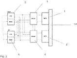
- Figures 1 and 2 discloses an embodiment of the control system for an actuator for a flight control surface of an aircraft.
- the aircraft comprises a first actuator (1) and a second actuator (2) in connection with a flight control surface (10) for its movement.
- the aircraft further comprises a primary flight control computer (5) and a secondary flight control computer (6).
- the primary flight control computer (5) is configured to provide the control system with a set position digital signal of the first actuator (1).
- the secondary flight control computer (6) is configured to provide the control system with a set position digital signal of the second actuator (2).
- the actuators (1, 2) comprise servovalves that comprise a servovalve and a solenoid.
- the shown control system comprises:
- the shown first control unit (3) comprises:
- the first analog controlling element (20) is configured to:
- a second control unit (4) would comprise:
- the first control unit (3) is additionally configured to receive the set position of the second actuator (2) and the second control unit (4) is configured to receive the set position of the first actuator (1) for redundancy purposes.
- the analog controlling elements (20) comprise a first and a second load controlling element (16.1, 17.1, 16.2, 17.2).
- the load controlling elements comprise a pass filter (17.1, 17.2) and a controller (16.1, 16.2).
- the first load controlling element (16.1, 17.2) is adapted to calculate the load sharing between the first and the second actuators (1, 2) and the deviation of the actuator (1, 2) with respect to the load sharing target in a transient period of the load.
- the second load controlling element (16.2, 17.2) is adapted to calculate the load sharing between the first and the second actuators (1, 2) and the deviation of the actuator (1, 2) with respect to the load sharing target in a stabilized period of the load.
- Figure 4 shows the evolution over time of the force in a transient period and in a stabilized period.
- the invention is also able to control the load in both periods of the load.
- the analog controlling elements (20) are configured to calculate the load sharing between the first and the second actuators (1, 2) by subtracting the measured analog signal of the load sensor (7.2) of the other actuator (2) from the measured analog signal of the load sensor (7.2) of its actuator (1).
- the analog controlling elements (20) of the first control unit (3) are configured to calculate the load sharing between the first and the second actuators (1, 2) by subtracting the measured analog signal of the load sensor (7.2) of the second actuator (2) from the measured analog signal of the load sensor (7.2) of the first actuator (1).
- the analog controlling elements (20) of the second control unit (4) are configured to calculate the load sharing between the first and the second actuators (1, 2) by subtracting the measured analog signal of the load sensor (7.2) of the first actuator (1) from the measured analog signal of the load sensor (7.2) of the second actuator (2).
- the analog controlling element (20) disclosed in figure 1 comprises an analog controller (9) and an analog load controlling element (16.1, 16.2, 17.1, 17.2).
- the analog controller (9), that may be a P controller (9), is adapted to receive:
- analog controller (9) is configured to:
- analog load controlling element (16.1, 16.2, 17.1, 17.2) of figure 1 is:
- the analog load controlling elements (16.1, 16.2, 17.1, 17.2) comprise a first and a second load controller (16.1, 16.2).
- the first load controller (16.1) is adapted to control the load in the transient period of the load and the second load controller (16.2) is adapted to control the load in the stabilised period of the load.
- the analog load controlling elements (16.1, 16.2, 17.1, 17.2) comprise a low pass filter (17.1) adapted to feed the first load controller (16.1) and a high pass filter (17.2) adapted to feed the second load controller (16.2).
- the first and second pass filters (17.1, 17.2) are adapted to receive the measured analog signals of the load sensors (7.2) of the first and of the second actuator (1, 2).
- the measured signals are instrumented and adapted for computing the first period of load-sharing, i.e., differential value in the stabilized movement, and also for the second period of load-sharing, i.e., transient movements.
- stabilized movement period means the differential load value between actuators in low frequency range and typically this difference is used to help the actuators (1, 2) to work in same load conditions, ideally 50%-50% load sharing.
- the second period based on transients means high peaks of load in actuators (1, 2) in high frequency range.
- controllers (16.1, 16.2) are designed with different control goals, in order to allow an independent correction of both terms.
- controllers (16.1, 16.2) and filters (17.1, 17.2) are included:
- the load-sharing control is directly implemented in analog control by the control units (3, 4) in order to maximize the band width of this control and report to the primary flight control computer (5) and secondary flight control computer (6) for its validation.
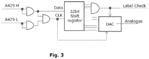
- control units (3, 4) comprise a shift register (11) configured to communicate with the flight control computers (5, 6) for receiving the set position of the actuators (1, 2) and to the analog converter (8, 9) for sending the output signal of the shift register (11).
- the provided signal also comprises data for its checking, specifically a message identifier.
- the control unit (3, 4) comprises a label check.
- the validation of commands is performed internally in the control unit (3, 4) to activate the control of the actuator (1, 2).
- the shift register (11) is a cascade of flip flops, sharing the same clock, in which the output of each flip-flop is connected to the "data" input of the next flip-flop in the chain, resulting in a circuit that shifts by one position the "bit array” stored in it, “shifting in” the data present at its input and 'shifting out' the last bit in the array, at each transition of the clock input.
- both commands are then consolidated and validated by checking that the difference of the signals provided by both commands is under a set value.
- control units (3, 4) comprise a first shift register (11.1) and a second shift register (11.2).
- the first shift register (11.1) is configured to communicate with a primary control computer (5.1) and the second shift resistor configured to communicate with a secondary control computer (5.2).
- the control units (3, 4) comprise two input shift resisters (11.1, 11.2) for redundancy and single fault.
- the flight control computer (5, 6) has a duplex digital communication so that a first (5.1, 6.1) and a second (5.2, 6.2) control computer exist. It also allows to consolidate and validate the internal data sent from the control unit (3, 4).
- the flight control computers (5, 6) comprise two wires wherein the same data circulates through said wires, but the information is inverted. In this way, if one of the wires fails the other wire is still alive. This is a redundant system which improves the safety of the system.
- Figure 2 discloses that the primary and secondary aircraft flight control computers (5, 6) may command both control units (3, 4) even if the other one is malfunctioning.
- the control unit (3, 4) finally comprises a filter (15) for filtering the Eigen-modal band-rejection.
- the control unit (3, 4) comprises an analog to digital converter (12) configured to receive the measured signal of the analog sensors (7.1, 7.2) and with the flight computers (5, 6). More specifically, the shown embodiment comprises two analog to digital converters (12) for redundancy. Data are sent by two buses to avoid that the simple failure of a component causes a communication failure.
- control unit (3, 4) comprises a demodulation unit (13) located between the analog sensors (7.1, 7.2) and the analog to digital converter (12).
- the control unit (3, 4) comprises a switch (14) in connection with the actuator (1, 2) and commanded by discrete signals coming from the flight control computer (5, 6). In case of failure or malfunction, three discrete signals are provided in order to remove the control and the activation of the actuator (1, 2). In this way, a failed actuator (1, 2) or control unit (3, 4) could be commanded to damping mode directly by flight control computer (5, 6). If the aircraft flight control computer (5, 6) detects any malfunction in the system, it operates the switch (14) inactivating the servo valve and the solenoid.
- the monitoring could be performed by the primary flight control computer (5) and the secondary flight control computer (6) in parallel to validate commands from the control unit (3, 4) during operation.
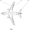
- Figure 5 discloses an aircraft comprising:
- control method for an actuator for a flight control surface of an aircraft comprising the following steps:
Landscapes
- Engineering & Computer Science (AREA)
- Automation & Control Theory (AREA)
- Aviation & Aerospace Engineering (AREA)
- Feedback Control In General (AREA)
Priority Applications (2)
| Application Number | Priority Date | Filing Date | Title |
|---|---|---|---|
| ES20382618T ES2969875T3 (es) | 2020-07-09 | 2020-07-09 | Sistema y método de control de un actuador para una superficie de control de vuelo de una aeronave |
| EP20382618.5A EP3936429B1 (fr) | 2020-07-09 | 2020-07-09 | Système et procédé de commande pour un actionneur d'une surface de commande de vol d'un aéronef |
Applications Claiming Priority (1)
| Application Number | Priority Date | Filing Date | Title |
|---|---|---|---|
| EP20382618.5A EP3936429B1 (fr) | 2020-07-09 | 2020-07-09 | Système et procédé de commande pour un actionneur d'une surface de commande de vol d'un aéronef |
Publications (2)
| Publication Number | Publication Date |
|---|---|
| EP3936429A1 true EP3936429A1 (fr) | 2022-01-12 |
| EP3936429B1 EP3936429B1 (fr) | 2023-11-29 |
Family
ID=71607889
Family Applications (1)
| Application Number | Title | Priority Date | Filing Date |
|---|---|---|---|
| EP20382618.5A Active EP3936429B1 (fr) | 2020-07-09 | 2020-07-09 | Système et procédé de commande pour un actionneur d'une surface de commande de vol d'un aéronef |
Country Status (2)
| Country | Link |
|---|---|
| EP (1) | EP3936429B1 (fr) |
| ES (1) | ES2969875T3 (fr) |
Cited By (1)
| Publication number | Priority date | Publication date | Assignee | Title |
|---|---|---|---|---|
| US12366464B2 (en) | 2023-02-06 | 2025-07-22 | Honeywell International, Inc. | Aircraft flight control surface position sensing system |
Citations (4)
| Publication number | Priority date | Publication date | Assignee | Title |
|---|---|---|---|---|
| US5129310A (en) * | 1990-06-15 | 1992-07-14 | Hydraulic Units, Incorporated | Auto rigging for servo actuator system |
| US20130026298A1 (en) * | 2008-11-25 | 2013-01-31 | The Boeing Company | Actuator force equalization controller |
| US20180362149A1 (en) * | 2017-06-14 | 2018-12-20 | The Boeing Company | Methods and apparatus for controlling aircraft flight control surfaces |
| US20190127049A1 (en) * | 2017-10-31 | 2019-05-02 | The Boeing Company | Adaptive feedback control of force fighting in hybrid actuation systems |
-
2020
- 2020-07-09 EP EP20382618.5A patent/EP3936429B1/fr active Active
- 2020-07-09 ES ES20382618T patent/ES2969875T3/es active Active
Patent Citations (4)
| Publication number | Priority date | Publication date | Assignee | Title |
|---|---|---|---|---|
| US5129310A (en) * | 1990-06-15 | 1992-07-14 | Hydraulic Units, Incorporated | Auto rigging for servo actuator system |
| US20130026298A1 (en) * | 2008-11-25 | 2013-01-31 | The Boeing Company | Actuator force equalization controller |
| US20180362149A1 (en) * | 2017-06-14 | 2018-12-20 | The Boeing Company | Methods and apparatus for controlling aircraft flight control surfaces |
| US20190127049A1 (en) * | 2017-10-31 | 2019-05-02 | The Boeing Company | Adaptive feedback control of force fighting in hybrid actuation systems |
Cited By (1)
| Publication number | Priority date | Publication date | Assignee | Title |
|---|---|---|---|---|
| US12366464B2 (en) | 2023-02-06 | 2025-07-22 | Honeywell International, Inc. | Aircraft flight control surface position sensing system |
Also Published As
| Publication number | Publication date |
|---|---|
| EP3936429B1 (fr) | 2023-11-29 |
| ES2969875T3 (es) | 2024-05-23 |
Similar Documents
| Publication | Publication Date | Title |
|---|---|---|
| US8245967B2 (en) | Actuator force equalization controller | |
| EP2381322B1 (fr) | Système redondant de contrôle d'actionneur | |
| US6334592B1 (en) | Flight control apparatus for helicopters | |
| US10759520B2 (en) | Flight control system and method of use | |
| US20140303812A1 (en) | Backup control system | |
| EP2343613A2 (fr) | Système de contrôle de vol | |
| US12140033B2 (en) | Valve position control | |
| EP2434356A2 (fr) | Échantillonnage intégré et filtrage pour commande multi-vitesses d'un actionneur électro-mécanique | |
| EP3626571B1 (fr) | Architecture de commande pour un véhicule | |
| US20180290730A1 (en) | Aircraft flight control system | |
| US20200306966A1 (en) | Trajectory planning unit, valve arrangement and method | |
| EP3936429B1 (fr) | Système et procédé de commande pour un actionneur d'une surface de commande de vol d'un aéronef | |
| US20140231591A1 (en) | Aircraft and control method therefor | |
| CN110963025B (zh) | 飞行器制动系统架构 | |
| US20100318245A1 (en) | Flight control system | |
| JP2011136630A (ja) | アクチュエータ制御システム | |
| US12151804B2 (en) | Actuator control for force fight mitigation | |
| US20120221262A1 (en) | Electronic device integrity monitoring apparatus | |
| KR20210007402A (ko) | 멀티콥터 제어 시스템 및 그 방법 | |
| CN108216580A (zh) | 用于控制飞行器的执行器的执行器控制装置 | |
| EP4625746A1 (fr) | Système de commande pour un système d'alimentation avec au moins deux canaux de commande et un intégrateur commun | |
| CN101989069B (zh) | 力纷争试验方法 | |
| US5783923A (en) | Method and apparatus for multiple-input, multiple output feedback control of variable load systems | |
| CN112904832B (zh) | 一种基于Nussbaum增益函数的传感器容错控制方法 | |
| Röben et al. | An innovative all-active hybrid actuation system demonstrator |
Legal Events
| Date | Code | Title | Description |
|---|---|---|---|
| PUAI | Public reference made under article 153(3) epc to a published international application that has entered the european phase |
Free format text: ORIGINAL CODE: 0009012 |
|
| STAA | Information on the status of an ep patent application or granted ep patent |
Free format text: STATUS: THE APPLICATION HAS BEEN PUBLISHED |
|
| AK | Designated contracting states |
Kind code of ref document: A1 Designated state(s): AL AT BE BG CH CY CZ DE DK EE ES FI FR GB GR HR HU IE IS IT LI LT LU LV MC MK MT NL NO PL PT RO RS SE SI SK SM TR |
|
| B565 | Issuance of search results under rule 164(2) epc |
Effective date: 20201209 |
|
| STAA | Information on the status of an ep patent application or granted ep patent |
Free format text: STATUS: REQUEST FOR EXAMINATION WAS MADE |
|
| 17P | Request for examination filed |
Effective date: 20220623 |
|
| RBV | Designated contracting states (corrected) |
Designated state(s): AL AT BE BG CH CY CZ DE DK EE ES FI FR GB GR HR HU IE IS IT LI LT LU LV MC MK MT NL NO PL PT RO RS SE SI SK SM TR |
|
| GRAP | Despatch of communication of intention to grant a patent |
Free format text: ORIGINAL CODE: EPIDOSNIGR1 |
|
| STAA | Information on the status of an ep patent application or granted ep patent |
Free format text: STATUS: GRANT OF PATENT IS INTENDED |
|
| RIC1 | Information provided on ipc code assigned before grant |
Ipc: B64C 13/50 20060101ALI20230628BHEP Ipc: B64C 13/00 20060101AFI20230628BHEP |
|
| INTG | Intention to grant announced |
Effective date: 20230728 |
|
| GRAS | Grant fee paid |
Free format text: ORIGINAL CODE: EPIDOSNIGR3 |
|
| GRAA | (expected) grant |
Free format text: ORIGINAL CODE: 0009210 |
|
| STAA | Information on the status of an ep patent application or granted ep patent |
Free format text: STATUS: THE PATENT HAS BEEN GRANTED |
|
| AK | Designated contracting states |
Kind code of ref document: B1 Designated state(s): AL AT BE BG CH CY CZ DE DK EE ES FI FR GB GR HR HU IE IS IT LI LT LU LV MC MK MT NL NO PL PT RO RS SE SI SK SM TR |
|
| REG | Reference to a national code |
Ref country code: GB Ref legal event code: FG4D |
|
| REG | Reference to a national code |
Ref country code: CH Ref legal event code: EP |
|
| REG | Reference to a national code |
Ref country code: DE Ref legal event code: R096 Ref document number: 602020021838 Country of ref document: DE |
|
| REG | Reference to a national code |
Ref country code: IE Ref legal event code: FG4D |
|
| REG | Reference to a national code |
Ref country code: LT Ref legal event code: MG9D |
|
| REG | Reference to a national code |
Ref country code: NL Ref legal event code: MP Effective date: 20231129 |
|
| PG25 | Lapsed in a contracting state [announced via postgrant information from national office to epo] |
Ref country code: GR Free format text: LAPSE BECAUSE OF FAILURE TO SUBMIT A TRANSLATION OF THE DESCRIPTION OR TO PAY THE FEE WITHIN THE PRESCRIBED TIME-LIMIT Effective date: 20240301 |
|
| PG25 | Lapsed in a contracting state [announced via postgrant information from national office to epo] |
Ref country code: IS Free format text: LAPSE BECAUSE OF FAILURE TO SUBMIT A TRANSLATION OF THE DESCRIPTION OR TO PAY THE FEE WITHIN THE PRESCRIBED TIME-LIMIT Effective date: 20240329 |
|
| PG25 | Lapsed in a contracting state [announced via postgrant information from national office to epo] |
Ref country code: LT Free format text: LAPSE BECAUSE OF FAILURE TO SUBMIT A TRANSLATION OF THE DESCRIPTION OR TO PAY THE FEE WITHIN THE PRESCRIBED TIME-LIMIT Effective date: 20231129 |
|
| PG25 | Lapsed in a contracting state [announced via postgrant information from national office to epo] |
Ref country code: LT Free format text: LAPSE BECAUSE OF FAILURE TO SUBMIT A TRANSLATION OF THE DESCRIPTION OR TO PAY THE FEE WITHIN THE PRESCRIBED TIME-LIMIT Effective date: 20231129 Ref country code: IS Free format text: LAPSE BECAUSE OF FAILURE TO SUBMIT A TRANSLATION OF THE DESCRIPTION OR TO PAY THE FEE WITHIN THE PRESCRIBED TIME-LIMIT Effective date: 20240329 Ref country code: GR Free format text: LAPSE BECAUSE OF FAILURE TO SUBMIT A TRANSLATION OF THE DESCRIPTION OR TO PAY THE FEE WITHIN THE PRESCRIBED TIME-LIMIT Effective date: 20240301 Ref country code: BG Free format text: LAPSE BECAUSE OF FAILURE TO SUBMIT A TRANSLATION OF THE DESCRIPTION OR TO PAY THE FEE WITHIN THE PRESCRIBED TIME-LIMIT Effective date: 20240229 |
|
| REG | Reference to a national code |
Ref country code: AT Ref legal event code: MK05 Ref document number: 1635876 Country of ref document: AT Kind code of ref document: T Effective date: 20231129 |
|
| PG25 | Lapsed in a contracting state [announced via postgrant information from national office to epo] |
Ref country code: NL Free format text: LAPSE BECAUSE OF FAILURE TO SUBMIT A TRANSLATION OF THE DESCRIPTION OR TO PAY THE FEE WITHIN THE PRESCRIBED TIME-LIMIT Effective date: 20231129 |
|
| REG | Reference to a national code |
Ref country code: ES Ref legal event code: FG2A Ref document number: 2969875 Country of ref document: ES Kind code of ref document: T3 Effective date: 20240523 |
|
| PG25 | Lapsed in a contracting state [announced via postgrant information from national office to epo] |
Ref country code: SE Free format text: LAPSE BECAUSE OF FAILURE TO SUBMIT A TRANSLATION OF THE DESCRIPTION OR TO PAY THE FEE WITHIN THE PRESCRIBED TIME-LIMIT Effective date: 20231129 Ref country code: RS Free format text: LAPSE BECAUSE OF FAILURE TO SUBMIT A TRANSLATION OF THE DESCRIPTION OR TO PAY THE FEE WITHIN THE PRESCRIBED TIME-LIMIT Effective date: 20231129 Ref country code: PL Free format text: LAPSE BECAUSE OF FAILURE TO SUBMIT A TRANSLATION OF THE DESCRIPTION OR TO PAY THE FEE WITHIN THE PRESCRIBED TIME-LIMIT Effective date: 20231129 Ref country code: NO Free format text: LAPSE BECAUSE OF FAILURE TO SUBMIT A TRANSLATION OF THE DESCRIPTION OR TO PAY THE FEE WITHIN THE PRESCRIBED TIME-LIMIT Effective date: 20240229 Ref country code: NL Free format text: LAPSE BECAUSE OF FAILURE TO SUBMIT A TRANSLATION OF THE DESCRIPTION OR TO PAY THE FEE WITHIN THE PRESCRIBED TIME-LIMIT Effective date: 20231129 Ref country code: LV Free format text: LAPSE BECAUSE OF FAILURE TO SUBMIT A TRANSLATION OF THE DESCRIPTION OR TO PAY THE FEE WITHIN THE PRESCRIBED TIME-LIMIT Effective date: 20231129 Ref country code: HR Free format text: LAPSE BECAUSE OF FAILURE TO SUBMIT A TRANSLATION OF THE DESCRIPTION OR TO PAY THE FEE WITHIN THE PRESCRIBED TIME-LIMIT Effective date: 20231129 |
|
| PG25 | Lapsed in a contracting state [announced via postgrant information from national office to epo] |
Ref country code: DK Free format text: LAPSE BECAUSE OF FAILURE TO SUBMIT A TRANSLATION OF THE DESCRIPTION OR TO PAY THE FEE WITHIN THE PRESCRIBED TIME-LIMIT Effective date: 20231129 |
|
| PG25 | Lapsed in a contracting state [announced via postgrant information from national office to epo] |
Ref country code: CZ Free format text: LAPSE BECAUSE OF FAILURE TO SUBMIT A TRANSLATION OF THE DESCRIPTION OR TO PAY THE FEE WITHIN THE PRESCRIBED TIME-LIMIT Effective date: 20231129 Ref country code: AT Free format text: LAPSE BECAUSE OF FAILURE TO SUBMIT A TRANSLATION OF THE DESCRIPTION OR TO PAY THE FEE WITHIN THE PRESCRIBED TIME-LIMIT Effective date: 20231129 |
|
| PG25 | Lapsed in a contracting state [announced via postgrant information from national office to epo] |
Ref country code: SK Free format text: LAPSE BECAUSE OF FAILURE TO SUBMIT A TRANSLATION OF THE DESCRIPTION OR TO PAY THE FEE WITHIN THE PRESCRIBED TIME-LIMIT Effective date: 20231129 |
|
| PG25 | Lapsed in a contracting state [announced via postgrant information from national office to epo] |
Ref country code: SM Free format text: LAPSE BECAUSE OF FAILURE TO SUBMIT A TRANSLATION OF THE DESCRIPTION OR TO PAY THE FEE WITHIN THE PRESCRIBED TIME-LIMIT Effective date: 20231129 Ref country code: SK Free format text: LAPSE BECAUSE OF FAILURE TO SUBMIT A TRANSLATION OF THE DESCRIPTION OR TO PAY THE FEE WITHIN THE PRESCRIBED TIME-LIMIT Effective date: 20231129 Ref country code: RO Free format text: LAPSE BECAUSE OF FAILURE TO SUBMIT A TRANSLATION OF THE DESCRIPTION OR TO PAY THE FEE WITHIN THE PRESCRIBED TIME-LIMIT Effective date: 20231129 Ref country code: IT Free format text: LAPSE BECAUSE OF FAILURE TO SUBMIT A TRANSLATION OF THE DESCRIPTION OR TO PAY THE FEE WITHIN THE PRESCRIBED TIME-LIMIT Effective date: 20231129 Ref country code: EE Free format text: LAPSE BECAUSE OF FAILURE TO SUBMIT A TRANSLATION OF THE DESCRIPTION OR TO PAY THE FEE WITHIN THE PRESCRIBED TIME-LIMIT Effective date: 20231129 Ref country code: DK Free format text: LAPSE BECAUSE OF FAILURE TO SUBMIT A TRANSLATION OF THE DESCRIPTION OR TO PAY THE FEE WITHIN THE PRESCRIBED TIME-LIMIT Effective date: 20231129 Ref country code: CZ Free format text: LAPSE BECAUSE OF FAILURE TO SUBMIT A TRANSLATION OF THE DESCRIPTION OR TO PAY THE FEE WITHIN THE PRESCRIBED TIME-LIMIT Effective date: 20231129 Ref country code: AT Free format text: LAPSE BECAUSE OF FAILURE TO SUBMIT A TRANSLATION OF THE DESCRIPTION OR TO PAY THE FEE WITHIN THE PRESCRIBED TIME-LIMIT Effective date: 20231129 |
|
| PG25 | Lapsed in a contracting state [announced via postgrant information from national office to epo] |
Ref country code: PT Free format text: LAPSE BECAUSE OF FAILURE TO SUBMIT A TRANSLATION OF THE DESCRIPTION OR TO PAY THE FEE WITHIN THE PRESCRIBED TIME-LIMIT Effective date: 20240401 |
|
| PG25 | Lapsed in a contracting state [announced via postgrant information from national office to epo] |
Ref country code: PT Free format text: LAPSE BECAUSE OF FAILURE TO SUBMIT A TRANSLATION OF THE DESCRIPTION OR TO PAY THE FEE WITHIN THE PRESCRIBED TIME-LIMIT Effective date: 20240401 |
|
| REG | Reference to a national code |
Ref country code: DE Ref legal event code: R097 Ref document number: 602020021838 Country of ref document: DE |
|
| PLBE | No opposition filed within time limit |
Free format text: ORIGINAL CODE: 0009261 |
|
| STAA | Information on the status of an ep patent application or granted ep patent |
Free format text: STATUS: NO OPPOSITION FILED WITHIN TIME LIMIT |
|
| PG25 | Lapsed in a contracting state [announced via postgrant information from national office to epo] |
Ref country code: SI Free format text: LAPSE BECAUSE OF FAILURE TO SUBMIT A TRANSLATION OF THE DESCRIPTION OR TO PAY THE FEE WITHIN THE PRESCRIBED TIME-LIMIT Effective date: 20231129 |
|
| PG25 | Lapsed in a contracting state [announced via postgrant information from national office to epo] |
Ref country code: SI Free format text: LAPSE BECAUSE OF FAILURE TO SUBMIT A TRANSLATION OF THE DESCRIPTION OR TO PAY THE FEE WITHIN THE PRESCRIBED TIME-LIMIT Effective date: 20231129 |
|
| 26N | No opposition filed |
Effective date: 20240830 |
|
| PG25 | Lapsed in a contracting state [announced via postgrant information from national office to epo] |
Ref country code: MC Free format text: LAPSE BECAUSE OF FAILURE TO SUBMIT A TRANSLATION OF THE DESCRIPTION OR TO PAY THE FEE WITHIN THE PRESCRIBED TIME-LIMIT Effective date: 20231129 |
|
| REG | Reference to a national code |
Ref country code: CH Ref legal event code: PL |
|
| PG25 | Lapsed in a contracting state [announced via postgrant information from national office to epo] |
Ref country code: LU Free format text: LAPSE BECAUSE OF NON-PAYMENT OF DUE FEES Effective date: 20240709 |
|
| GBPC | Gb: european patent ceased through non-payment of renewal fee |
Effective date: 20240709 |
|
| PG25 | Lapsed in a contracting state [announced via postgrant information from national office to epo] |
Ref country code: LU Free format text: LAPSE BECAUSE OF NON-PAYMENT OF DUE FEES Effective date: 20240709 |
|
| PG25 | Lapsed in a contracting state [announced via postgrant information from national office to epo] |
Ref country code: BE Free format text: LAPSE BECAUSE OF NON-PAYMENT OF DUE FEES Effective date: 20240731 Ref country code: CH Free format text: LAPSE BECAUSE OF NON-PAYMENT OF DUE FEES Effective date: 20240731 |
|
| PG25 | Lapsed in a contracting state [announced via postgrant information from national office to epo] |
Ref country code: GB Free format text: LAPSE BECAUSE OF NON-PAYMENT OF DUE FEES Effective date: 20240709 |
|
| REG | Reference to a national code |
Ref country code: BE Ref legal event code: MM Effective date: 20240731 |
|
| PG25 | Lapsed in a contracting state [announced via postgrant information from national office to epo] |
Ref country code: IE Free format text: LAPSE BECAUSE OF NON-PAYMENT OF DUE FEES Effective date: 20240709 |
|
| PG25 | Lapsed in a contracting state [announced via postgrant information from national office to epo] |
Ref country code: FI Free format text: LAPSE BECAUSE OF FAILURE TO SUBMIT A TRANSLATION OF THE DESCRIPTION OR TO PAY THE FEE WITHIN THE PRESCRIBED TIME-LIMIT Effective date: 20231129 |
|
| PGFP | Annual fee paid to national office [announced via postgrant information from national office to epo] |
Ref country code: ES Payment date: 20250827 Year of fee payment: 6 |
|
| PGFP | Annual fee paid to national office [announced via postgrant information from national office to epo] |
Ref country code: DE Payment date: 20250722 Year of fee payment: 6 |
|
| PGFP | Annual fee paid to national office [announced via postgrant information from national office to epo] |
Ref country code: FR Payment date: 20250725 Year of fee payment: 6 |
|
| PG25 | Lapsed in a contracting state [announced via postgrant information from national office to epo] |
Ref country code: CY Free format text: LAPSE BECAUSE OF FAILURE TO SUBMIT A TRANSLATION OF THE DESCRIPTION OR TO PAY THE FEE WITHIN THE PRESCRIBED TIME-LIMIT; INVALID AB INITIO Effective date: 20200709 |
|
| PG25 | Lapsed in a contracting state [announced via postgrant information from national office to epo] |
Ref country code: HU Free format text: LAPSE BECAUSE OF FAILURE TO SUBMIT A TRANSLATION OF THE DESCRIPTION OR TO PAY THE FEE WITHIN THE PRESCRIBED TIME-LIMIT; INVALID AB INITIO Effective date: 20200709 |