EP3936664A1 - Système de fixation pour fixation d'un dispositif de rail supplémentaire à un système de rails et clôture de protection de rail - Google Patents
Système de fixation pour fixation d'un dispositif de rail supplémentaire à un système de rails et clôture de protection de rail Download PDFInfo
- Publication number
- EP3936664A1 EP3936664A1 EP21184553.2A EP21184553A EP3936664A1 EP 3936664 A1 EP3936664 A1 EP 3936664A1 EP 21184553 A EP21184553 A EP 21184553A EP 3936664 A1 EP3936664 A1 EP 3936664A1
- Authority
- EP
- European Patent Office
- Prior art keywords
- fence
- rail
- fastening
- track
- locking bolt
- Prior art date
- Legal status (The legal status is an assumption and is not a legal conclusion. Google has not performed a legal analysis and makes no representation as to the accuracy of the status listed.)
- Withdrawn
Links
Images




Classifications
-
- E—FIXED CONSTRUCTIONS
- E01—CONSTRUCTION OF ROADS, RAILWAYS, OR BRIDGES
- E01B—PERMANENT WAY; PERMANENT-WAY TOOLS; MACHINES FOR MAKING RAILWAYS OF ALL KINDS
- E01B26/00—Tracks or track components not covered by any one of the preceding groups
- E01B26/005—Means for fixing posts, barriers, fences or the like to rails
Definitions
- the invention relates to a fastening element for fastening an additional track device, in particular for fastening a track protection fence or a holding device for it on a track system according to the preamble of claim 1, a fastening system according to claim 9, and a track protection fence system according to claim 10
- Additional track devices such as track protection fences, noise protection devices, signals or signs, are often used on track installations or track systems in order to secure the track installations, to reduce noise or to attach appropriate information, e.g. for the train driver.
- the additional track devices must be securely attached to the track systems and fixed in such a way that, for example, a secure hold of the additional track devices on the track systems is guaranteed even at high speeds of passing trains or in bad weather.
- a rail foot bracket via which a track protection fence is attached to a rail, is from the German utility model DE 20 2005 008 225 U1 known.
- the rail foot holder is fastened to the rail by clamping the rail foot on both sides by means of angle pieces that encompass it.
- fastening element should be able to be used with different types of sleepers, in particular sleepers of different widths, and with different types of rails, in particular rail feet with different designs.
- a fastening system with such a Provide fastening system.
- an advantageous and safe track protection fence system is to be provided.
- the locking bolt receiving openings are arranged on the legs in such a way that a locking bolt that can be inserted into the locking bolt receiving openings between a rail web of the rail of the track system and a rail fixation that fixes the rail, in particular a fastening screw and/or a tension clamp, via which the rail can be fastened to a sleeper or a Fixed roadway is fixed, can be arranged.
- a locking bolt that can be inserted into the locking bolt receiving openings between a rail web of the rail of the track system and a rail fixation that fixes the rail, in particular a fastening screw and/or a tension clamp, via which the rail can be fastened to a sleeper or a Fixed roadway is fixed can be arranged.
- a fast and reliable securing of the fastening element on the track system and then also a speedy unlocking and removal of the fastening element from the rail or the track system.
- the simple and rapid securing and unlocking of the fastening element on a rail is particularly advantageous when attaching additional track devices that are only to be temporarily attached to a track system and can be fastened to the track system via the fastening element, such as a protective track fence used to secure a track construction site.
- the fastening element preferably has an essentially U-shaped configuration, with the legs in particular enclosing an essentially right angle with the central part.
- the U-shaped configuration and the legs spaced apart from one another allow in particular an attachment of the fastening element to different types of sleepers, with the sleepers being able to be arranged in particular between the legs.
- the fastening element consists of the central part, the coupling element and the legs connected, in particular firmly connected, to it. Further components, in particular components that are not firmly connected to the legs or the central part, which could make the handling of the fastening element or its attachment to a track system more difficult or impair its stability, are not required.
- the legs each have a receptacle for at least partially accommodating a rail foot of the rail or for at least partially accommodating the rail foot and a rail foot fastening provided for fastening a rail foot on a sleeper, for example a fastening plate, of the track system.
- the receptacles are arranged in particular on the front ends of the legs remote from the central part. Those are particularly preferred Locking bolt receiving openings are each arranged above the recordings on the legs.
- the legs each have an essentially flat contact section that delimits the receptacle on an underside and that, when the fastening element is fastened to a track system, is at least partially on the underside of the rail or the rail foot and/or one of the rails fastening rail foot fastening, in particular a fastening plate mounted on a sleeper, is arranged.
- the contact section is preferably in contact with the underside of the rail.
- the legs of the fastening element each comprise a contact element that can be placed on a substrate and a side part that is arranged on the contact element and has the locking bolt receiving opening, or the legs consist of these.
- the front end of the contact element remote from the central part can in particular form the contact section delimiting the receptacle on an underside.
- the contact element can also protrude beyond the front end of the side part.
- the side parts can in particular be welded to the contact elements.
- the contact elements and/or the side parts and/or the central part are formed essentially flat, in particular from a metal plate.
- the two contact elements and the central part are particularly preferably formed in one piece or from a common piece.
- the coupling element which can in particular be a coupling tube, is designed for the detachable attachment of the additional track device.
- the coupling element is preferably arranged centrally between the legs on the middle part, in particular welded to it.
- this results in a stable configuration of the fastening element.
- the detachable attachment of the additional track device makes it easy to handle, especially easy to attach the fastening element to the track system. After the fastening element has been attached and secured to the track system, the additional track device can simply be connected to it via the coupling element and fixed to it.
- the subject matter of the invention is also a fastening system for fastening an additional track device, in particular for fastening a safety rail fence or a holding device for this to a track system.
- the fastening system comprises a locking bolt which can be introduced into the locking bolt receiving openings.
- the locking bolt preferably has a spring element at a first end and a securing element, in particular a tilting element, at its second end for releasably fixing the locking bolt in the locking bolt receiving openings.
- the spring element and the securing element each bear against an outer side of the locking bolt receiving openings.
- a further object of the invention is a railway safety fence system comprising a railway safety fence having at least one fence strut, preferably two, an upper and a lower fence strut, and at least one railway safety fence retaining system, preferably several railway safety fence retaining systems.
- the at least one fence strut of the rail protection fence which in particular runs horizontally or parallel to a rail of the track system, is preferably formed from rails connected via electrically insulating rail connectors.
- the fastener can be secured to a track system via a locking bolt.
- the fixing system via which the fence mount is fixed to the fastening element, preferably has an electrically insulating insulating connector piece, in particular an insulating connector piece which can be arranged on the fastening element or can be connected directly to it. Electrical insulation of the fixing system and thus the fence mount and the safety rail fence attached thereto from the fastening foot attached to a rail or the track system, in particular a track system having a conductor rail, is provided via the insulating connector piece.
- the electrically insulating rail connectors provide electrical insulation between adjacent rails of the fence strut that are connected to one another given, which prevents voltage spread over more than one spar length.
- the insulating connector piece attached to the fastening element and the electrically insulating spar connector connecting the spars of a fence strut provide double insulation of the rail protection fence system. This prevents the entire track protection fence system from being live if an insulation fails or is bridged.
- the rail protection fence retaining system comprises a support leg that can be connected to the fence mount and/or is guided in the fence mount to support the fence mount on a substrate.
- the support leg can be fixed at different positions or at different heights relative to the fence mount.
- the support foot enables vibrations that occur, in particular from trains running on the tracks or adjacent tracks, to be absorbed.
- due to the height adjustability of the support leg relative to the fence bracket it is possible to advantageously place the support leg on a subsurface, regardless of unevenness in the subsurface.
- a railway protection fence system 1 with several railway protection fence retaining systems 2 for holding a lower and an upper fence strut 80, 80' forming a railway protection fence is shown by way of example.
- the track protection fence systems 2 are each attached to a track system 3 comprising a rail 4, with the application of the track protection fence system 2 being shown as an example for attachment to four different track systems 3-1 to 3-4 is shown, which in 1 are shown arranged one behind the other in sections in the longitudinal direction of the rail 4 .
- This in 1 shown right track system 3-1 (first track system 3-1), shows an example of a slab track and seen from the right second to fourth configurations 3-2 to 3-4 of the track systems 3 show a normal track with different sleepers 8 on which the Rail 4 is fixed.
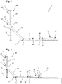
- FIG. 2 and 3 show a track safety fence system 2 of in 1 rail protection fence system 1 shown in a perspective view and in a side view.
- FIG. 3 is a side view of the first track system 3-1 1 attached track protection fence system 2 shown.
- the rail protection fence retaining system 2 comprises a fastening element 10, which can be secured to a track system 3 via a locking bolt 20, an insulating connector piece 30 connected to the fastening element 10, a first connecting element 40 connected to the insulating connector piece 30, a second connecting element 50, which can be connected via an in the Figures 2 to 4 connecting piece 45, not shown, is connected to the first connecting element 40, a fence bracket 60 connected to the second connecting element 50 and a support foot 70 connected to the fence bracket 60 Figures 5 and 6 and 11 through 14 and described in more detail below.
- the individual components of the rail protection fence retaining system 2 that are connected to one another are fixed to one another by means of tubular folding pins 90 or other fixing means introduced into corresponding openings in the individual components.
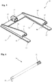
- Fastening element 10 shown in detail is used for releasably fastening the rail protection fence retaining system 2 to a track system 3.
- the fastening element 10 has an essentially U-shaped configuration with a first leg 11 and a second leg 11' spaced from this, which has a flat central part 12 are connected, on.
- the legs 11, 11 'in each case consist of a substantially flat contact element 13, 13' and each on the Contact elements 13, 13 'arranged, in particular with this welded side part 14, 14'.
- the central part 12 and the contact elements 13, 13' are in one piece, in particular formed from a metal plate.
- a coupling element 17, specifically a coupling tube with a substantially square cross-section, is located on the central part 12 in the middle between the legs 11, 11' for connection to the insulating connector piece 30 of the rail protection fence retaining system 2, as in particular in 3 and 4 is shown applied, in particular welded to it.
- the legs 11, 11' each have a receptacle 16, 16' at their front end remote from the central part 12, e.g. in the form of a recess for at least partially accommodating a rail foot 5 or a rail foot half of a Rail 4 as well as a locking bolt receiving opening 15, 15' arranged above the receptacle 16, 16', in particular a bore, into which the in 6 locking bolt 20 shown in detail and described in more detail below can be inserted.
- the receptacles 16, 16' of the side parts 14, 14' are delimited on the underside by a contact section which is formed in each case by the front end of the contact elements 13, 13' which is remote from the central part 12.
- the abutment section or the abutment elements 13, 13' protrude in particular somewhat beyond the front end of the side parts 14, 14', which is remote from the central part 12.
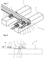
- the fastening of the fastening element 3 to a track system 3 is shown in an example in 7 and 8 shown, in which a section of the second track system 3-2 from 1 attached track protection fence retaining system 2 is shown in the region of the fastener 10 in a perspective view and in a side view.
- the second track system 3-2 includes a rail fixation that fixes the rail 4 on the sleeper 8, in particular a tension clamp 9' that fixes a rail foot 5 of the rail 4 and a tension clamp 9' on the sleeper 8 or a fastening screw 9 fixed on the sleeper 8.
- the rail 4 comprises a rail head 7 which is connected to the rail foot 5 via a rail web 6 .
- the contact elements 13, 13' are designed in such a way that the front end of the contact element 13, 13' remote from the central part 12 does not extend over the entire underside of the rail 4, i.e. not up to the side of the rail 4 or rail 4 remote from the central part 12 .
- the front end of the side parts 14, 14' which is remote from the central part 12, rests on the rail web 6 or at least close to it.
- Side parts 14, 14' lying on or near rail web 6 and sections of contact elements 13, 13' guided on the underside of rail 4 prevent or at least limit upward tilting of fastening element 10.
- the fastening element 10 is secured on the rail 4 via the locking bolts 20 which can be inserted into the locking bolt receiving openings 15, 15'.
- the locking bolt 20 is arranged between the rail web 6 and the rail fixation, here the head of the fastening screw 9 .
- the locking bolt 20 prevents the fastening element 10 from being removed from the rail 4 , in particular perpendicularly to the longitudinal axis of the rail 4 , ie transversely to the direction of travel of a rail vehicle running on the rail 4 .
- the locking bolt 20 As shown in 6 is shown in detail, at a first end, a spring element 21, in particular a compression spring and, at a second end, a securing element 22 designed as a tilting element.
- the spring element 21 of a locking bolt 20 secured in the locking bolt receiving openings 15, 15′ rests on the outside of a first side part 14, 14′ and the securing element 22 on the outside of the second side part 14, 14′ of the fastening element 10 .
- the fastening element 10 shown can be attached, secured and also detached from these in a simple and quick manner, in particular on different track systems 3 .
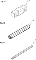
- the in 11 Isolating connector piece 30 shown in detail can be connected to the fastening element 10, such as in FIG 2 is shown.
- the insulating connector piece 30 can be introduced into the coupling element 17 and secured thereto via a tubular folding pin 90 which is not described in detail and which can be introduced into openings in the insulating connector piece 30 and the coupling element 17 .
- the insulating connector piece 30 preferably consists of an electrically insulating material, for example a glass fiber reinforced polyamide 6, in particular a 30% glass fiber reinforced polyamide 6 (PA6 GF30).
- the second connecting element 50 has a connecting piece receptacle 51, also designed as a square tube, into which the connecting piece 45 can be inserted and guided.
- the fixation of the first connecting element 40 with the insulating connector piece 30 and the fixing of the connecting elements 40, 50 with the connecting piece 45 also takes place via folding pins 90 that can be introduced into corresponding openings and are not described in detail, such as in FIGS Figures 2 to 4 is shown.
- the second connecting element 50 designed as a square tube fence bracket receptacle 52, in which a fence bracket support 61, in particular designed as a square tube fence bracket support 61 of the fence bracket 60 can be used and in this can be fixed via a tube folding pin 90 that can be introduced into corresponding openings.
- the fence mount receptacle 52 and the connecting piece receptacle 51 of the second connecting element 50 are connected to one another via a bevel 53 .
- the incline 53 has an angle of approximately 45° or 135° with a connecting piece 45 inserted into the connecting piece receptacle 51 and a fence retaining support 61 inserted into the fence mounting receptacle 52 .
- the fence bracket 60 on the fence bracket support 61 has an upper holding receptacle 62 and a lower holding receptacle 63.
- the fence struts 80, 80' can be secured in the holding receptacles 62, 62 by means of a locking element 64, 64', in particular a locking element 64, 64' arranged in a foldable manner on the retaining receptacles 62, 63.
- the fence struts 80, 80' forming the rail protection fence are made up of several in 17 spars 81 shown in detail together, with two spars 81, as in particular in 19 and in the in 20 shown section, about in 18 spar connectors 82 shown in detail are connected to one another.
- the spar connectors 82 are introduced partially or with one side each into the spars 81 and are releasably fixed via securing pins 83 introduced into corresponding openings in the spars 81 and the spar connectors 82 .
- the rail connectors 82 are in particular made of an electrically insulating material, in particular a glass fiber reinforced polyamide, for example PA6 GF30.
- the electrically insulating design of the spar connectors 82 prevents the voltage from being spread over a number of spars 82 or over a number of rail protection fence holding systems 2 holding the fence struts 80, 80'.
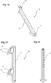
- the rail protection fence holding system 2 includes the 16 support leg 70 shown in detail.
- the support leg 70 is in the fence bracket 60 or in the fence bracket support 61 can be inserted and is guided in it and fixed with a tube folding pin 90.
- the support leg 70 is fixed to the fence bracket 60 and the fence bracket 60 is fixed to the fence bracket receptacle 52 of the second connecting element 50 by a single tubular folding pin 90, as in FIG 3 is shown. Due to the numerous openings arranged along the longitudinal axis of the support leg 70, via which a fixation on the fence bracket 60 takes place via a tubular folding pin 90, it is possible to fix the support leg 70 at different heights. This allows the fence bracket 60 to be supported by the support foot 70 on a subsurface, regardless of any unevenness that may be present or an existing slope.
Landscapes
- Engineering & Computer Science (AREA)
- Architecture (AREA)
- Civil Engineering (AREA)
- Structural Engineering (AREA)
- Train Traffic Observation, Control, And Security (AREA)
Applications Claiming Priority (1)
| Application Number | Priority Date | Filing Date | Title |
|---|---|---|---|
| DE202020103948.2U DE202020103948U1 (de) | 2020-07-08 | 2020-07-08 | Befestigungselement und Befestigungssystem zur Befestigung einer Gleiszusatzvorrichtung an einem Gleissystem sowie ein Gleisschutzzaunsystem |
Publications (1)
| Publication Number | Publication Date |
|---|---|
| EP3936664A1 true EP3936664A1 (fr) | 2022-01-12 |
Family
ID=76845111
Family Applications (1)
| Application Number | Title | Priority Date | Filing Date |
|---|---|---|---|
| EP21184553.2A Withdrawn EP3936664A1 (fr) | 2020-07-08 | 2021-07-08 | Système de fixation pour fixation d'un dispositif de rail supplémentaire à un système de rails et clôture de protection de rail |
Country Status (2)
| Country | Link |
|---|---|
| EP (1) | EP3936664A1 (fr) |
| DE (1) | DE202020103948U1 (fr) |
Families Citing this family (1)
| Publication number | Priority date | Publication date | Assignee | Title |
|---|---|---|---|---|
| DE102023128105A1 (de) * | 2023-10-13 | 2025-04-17 | Arc Allround Cleaning Rheinfelden Ag | Schienenfußhalterung |
Citations (6)
| Publication number | Priority date | Publication date | Assignee | Title |
|---|---|---|---|---|
| DE202005008225U1 (de) | 2005-05-25 | 2005-09-29 | Upz Sitech Gmbh | Gleiskörperschutzzaun |
| DE60023618T2 (de) * | 1999-08-03 | 2006-07-27 | F.Lli Dematteis S.R.L. | Stützeinrichtung für Gleisschienen |
| FR2904836A1 (fr) * | 2006-08-09 | 2008-02-15 | Europ De Travaux Ferroviaires | Dispositif permettant d'assurer la protection de personnes travaillant sur un chantier ferroviaire |
| DE202011052057U1 (de) | 2011-11-22 | 2011-12-30 | Art Asamer Rubber Technology Gmbh | Lärmschutzvorrichtung |
| DE102014108102A1 (de) * | 2014-06-10 | 2015-12-17 | Marcell Reimann | Gleissicherungsvorrichtung |
| EP3670742A1 (fr) * | 2018-12-21 | 2020-06-24 | Ten Hove Group B.V. | Dispositif de fixation de rails pour barrière de voie ferrée pour la protection ou la délimitation d'une section d'un rail, combinaison d'un rail et d'un certain nombre de dispositifs de fixation de rails |
Family Cites Families (4)
| Publication number | Priority date | Publication date | Assignee | Title |
|---|---|---|---|---|
| DE4406701C1 (de) | 1994-03-02 | 1995-08-31 | Geruestbau Broecking Gmbh | Halterung für ein Geländer an Eisenbahngleisen |
| CZ361196A3 (en) | 1994-06-16 | 1997-04-16 | Hansjurgen Oertner | Device for fastening a stand on a rail profile strip |
| SI0768429T1 (en) | 1995-10-10 | 2002-10-31 | Harald Müller | Railroad security fence |
| NL1006248C2 (nl) | 1997-06-06 | 1998-12-08 | Joseph Hubertus Marie Urlings | Inrichting die aan een spoorrail kan worden bevestigd, zodat met een aantal inrichtingen middelen kunnen worden verbonden ter afscherming van de spoorbaan. |
-
2020
- 2020-07-08 DE DE202020103948.2U patent/DE202020103948U1/de not_active Expired - Lifetime
-
2021
- 2021-07-08 EP EP21184553.2A patent/EP3936664A1/fr not_active Withdrawn
Patent Citations (6)
| Publication number | Priority date | Publication date | Assignee | Title |
|---|---|---|---|---|
| DE60023618T2 (de) * | 1999-08-03 | 2006-07-27 | F.Lli Dematteis S.R.L. | Stützeinrichtung für Gleisschienen |
| DE202005008225U1 (de) | 2005-05-25 | 2005-09-29 | Upz Sitech Gmbh | Gleiskörperschutzzaun |
| FR2904836A1 (fr) * | 2006-08-09 | 2008-02-15 | Europ De Travaux Ferroviaires | Dispositif permettant d'assurer la protection de personnes travaillant sur un chantier ferroviaire |
| DE202011052057U1 (de) | 2011-11-22 | 2011-12-30 | Art Asamer Rubber Technology Gmbh | Lärmschutzvorrichtung |
| DE102014108102A1 (de) * | 2014-06-10 | 2015-12-17 | Marcell Reimann | Gleissicherungsvorrichtung |
| EP3670742A1 (fr) * | 2018-12-21 | 2020-06-24 | Ten Hove Group B.V. | Dispositif de fixation de rails pour barrière de voie ferrée pour la protection ou la délimitation d'une section d'un rail, combinaison d'un rail et d'un certain nombre de dispositifs de fixation de rails |
Also Published As
| Publication number | Publication date |
|---|---|
| DE202020103948U1 (de) | 2021-10-11 |
Similar Documents
| Publication | Publication Date | Title |
|---|---|---|
| EP3936663B1 (fr) | Système de clôture de protection de rail | |
| DE19751625C2 (de) | Haltebügel zur Abstützung einer Absperrung an einer Gleisschiene | |
| EP3936664A1 (fr) | Système de fixation pour fixation d'un dispositif de rail supplémentaire à un système de rails et clôture de protection de rail | |
| EP3480054B1 (fr) | Séparations électriques à l'intérieur des rails conducteurs du plafond | |
| DE102012110948B4 (de) | Stromschienensystem | |
| EP2241674A2 (fr) | Système de création d'une voie de fuite, de secours ou de service dans des installations de voies ferrées | |
| DE202011001106U1 (de) | System zum horizontalen Ausrichten eines Gleisrostes einer festen Schienenfahrbahn | |
| DE102014108102B4 (de) | Gleissicherungsvorrichtung | |
| EP3356599B1 (fr) | Système et point de fixation permettant la fixation sans vis d'un rail pour un véhicule ferroviaire | |
| EP3424795A1 (fr) | Dispositif de fixation d'un commutateur de rails sur un rail | |
| EP2609255B1 (fr) | Système de fixation de rail | |
| AT396278B (de) | Stuetzvorrichtung | |
| WO2006094597A1 (fr) | Dispositif de montage pour des barres de distribution | |
| EP4538458B1 (fr) | Support de pied de rail | |
| DE4219199A1 (de) | Fahrweg für Magnetbahnen | |
| DE4220109C2 (de) | Halterung für Anbauteile an Schwellen | |
| DE102006001442B3 (de) | Vorrichtung zur Befestigung der Stromschiene für den Stromabnehmer eines Nahverkehrszuges an einer Hilfsbrücke im Rahmen von Bauarbeiten | |
| DE60102620T2 (de) | Verbindungsvorrichtung für Befestigungsstangen an einem Kraftfahrzeug | |
| DE29515884U1 (de) | Gleissicherungseinrichtung | |
| DE202023105926U1 (de) | Schienenfußhalterung | |
| EP0607396A1 (fr) | Dispositif de fixation d'un element de construction en forme de rail sur un systeme de contres-fiches diagonales | |
| CH702322B1 (de) | Mobile Entgleisungsvorrichtung. | |
| EP0969148A1 (fr) | Barrière de sécurité de chemin de fer | |
| DE10228434A1 (de) | Vorrichtung zur Sicherung von Ladung und spurgebundenes Fahrzeug | |
| DE102023121259A1 (de) | Mobile Signalmastanlage zur Fixierung an Bahnschienen |
Legal Events
| Date | Code | Title | Description |
|---|---|---|---|
| PUAI | Public reference made under article 153(3) epc to a published international application that has entered the european phase |
Free format text: ORIGINAL CODE: 0009012 |
|
| STAA | Information on the status of an ep patent application or granted ep patent |
Free format text: STATUS: THE APPLICATION HAS BEEN PUBLISHED |
|
| AK | Designated contracting states |
Kind code of ref document: A1 Designated state(s): AL AT BE BG CH CY CZ DE DK EE ES FI FR GB GR HR HU IE IS IT LI LT LU LV MC MK MT NL NO PL PT RO RS SE SI SK SM TR |
|
| B565 | Issuance of search results under rule 164(2) epc |
Effective date: 20211203 |
|
| STAA | Information on the status of an ep patent application or granted ep patent |
Free format text: STATUS: REQUEST FOR EXAMINATION WAS MADE |
|
| 17P | Request for examination filed |
Effective date: 20220712 |
|
| RBV | Designated contracting states (corrected) |
Designated state(s): AL AT BE BG CH CY CZ DE DK EE ES FI FR GB GR HR HU IE IS IT LI LT LU LV MC MK MT NL NO PL PT RO RS SE SI SK SM TR |
|
| STAA | Information on the status of an ep patent application or granted ep patent |
Free format text: STATUS: EXAMINATION IS IN PROGRESS |
|
| 17Q | First examination report despatched |
Effective date: 20230726 |
|
| STAA | Information on the status of an ep patent application or granted ep patent |
Free format text: STATUS: THE APPLICATION HAS BEEN WITHDRAWN |
|
| 18W | Application withdrawn |
Effective date: 20230828 |