EP3936670A1 - Pieu en béton et procédé d'accouplement de deux pieux en béton - Google Patents
Pieu en béton et procédé d'accouplement de deux pieux en béton Download PDFInfo
- Publication number
- EP3936670A1 EP3936670A1 EP21179955.6A EP21179955A EP3936670A1 EP 3936670 A1 EP3936670 A1 EP 3936670A1 EP 21179955 A EP21179955 A EP 21179955A EP 3936670 A1 EP3936670 A1 EP 3936670A1
- Authority
- EP
- European Patent Office
- Prior art keywords
- concrete pile
- pile element
- central opening
- screwing
- concrete
- Prior art date
- Legal status (The legal status is an assumption and is not a legal conclusion. Google has not performed a legal analysis and makes no representation as to the accuracy of the status listed.)
- Withdrawn
Links
Images




Classifications
-
- E—FIXED CONSTRUCTIONS
- E02—HYDRAULIC ENGINEERING; FOUNDATIONS; SOIL SHIFTING
- E02D—FOUNDATIONS; EXCAVATIONS; EMBANKMENTS; UNDERGROUND OR UNDERWATER STRUCTURES
- E02D5/00—Bulkheads, piles, or other structural elements specially adapted to foundation engineering
- E02D5/22—Piles
- E02D5/56—Screw piles
-
- E—FIXED CONSTRUCTIONS
- E02—HYDRAULIC ENGINEERING; FOUNDATIONS; SOIL SHIFTING
- E02D—FOUNDATIONS; EXCAVATIONS; EMBANKMENTS; UNDERGROUND OR UNDERWATER STRUCTURES
- E02D5/00—Bulkheads, piles, or other structural elements specially adapted to foundation engineering
- E02D5/22—Piles
- E02D5/24—Prefabricated piles
- E02D5/30—Prefabricated piles made of concrete or reinforced concrete or made of steel and concrete
-
- E—FIXED CONSTRUCTIONS
- E02—HYDRAULIC ENGINEERING; FOUNDATIONS; SOIL SHIFTING
- E02D—FOUNDATIONS; EXCAVATIONS; EMBANKMENTS; UNDERGROUND OR UNDERWATER STRUCTURES
- E02D5/00—Bulkheads, piles, or other structural elements specially adapted to foundation engineering
- E02D5/22—Piles
- E02D5/52—Piles composed of separable parts, e.g. telescopic tubes ; Piles composed of segments
- E02D5/523—Piles composed of separable parts, e.g. telescopic tubes ; Piles composed of segments composed of segments
- E02D5/526—Connection means between pile segments
-
- E—FIXED CONSTRUCTIONS
- E02—HYDRAULIC ENGINEERING; FOUNDATIONS; SOIL SHIFTING
- E02D—FOUNDATIONS; EXCAVATIONS; EMBANKMENTS; UNDERGROUND OR UNDERWATER STRUCTURES
- E02D7/00—Methods or apparatus for placing sheet pile bulkheads, piles, mouldpipes, or other moulds
- E02D7/22—Placing by screwing down
-
- E—FIXED CONSTRUCTIONS
- E02—HYDRAULIC ENGINEERING; FOUNDATIONS; SOIL SHIFTING
- E02D—FOUNDATIONS; EXCAVATIONS; EMBANKMENTS; UNDERGROUND OR UNDERWATER STRUCTURES
- E02D7/00—Methods or apparatus for placing sheet pile bulkheads, piles, mouldpipes, or other moulds
- E02D7/28—Placing of hollow pipes or mould pipes by means arranged inside the piles or pipes
Definitions
- the present invention relates to a concrete pile element, a set comprising at least one such concrete pile element and a screwing-in tool for the concrete pile element, and a method for coupling such concrete pile elements together, according to the preambles of the independent patent claims.
- Concrete screw piles are increasingly being used to create foundations in areas where the near-surface soil layers only have a low load-bearing capacity.
- driven piles In contrast to driven piles, they have the advantage that they can be driven into the ground without any vibrations or excessive noise emissions.
- they have a greater load-bearing capacity than driven piles or in-situ concrete piles of comparable dimensions.
- the concrete pile elements have steel rings at their ends which, after adjoining and aligning the ends of two consecutive concrete pile elements, are welded together circumferentially before both pile elements are screwed further together into the ground. This is necessary to ensure a durable and resilient axial and radial connection between the concrete pile elements.
- the object is therefore to provide technical solutions which do not have the aforementioned disadvantages of the prior art or at least partially avoid them.
- a first aspect of the invention relates to a concrete pile element, preferably for forming a screwed concrete pile for a foundation made up of several concrete pile elements according to the claims.
- the concrete pile element comprises a substantially cylindrical concrete shank having a central opening extending axially therethrough.
- This central opening has a substantially uniform, non-circular cross-section over its entire length, to enable a rotary form fit with a screwing-in tool for the purpose of transmitting a torque around the longitudinal axis of the concrete pile element to the latter.
- the ends of the concrete pile element are each formed by one half of a swivel joint, such that several of these concrete pile elements can be positively connected to one another in the longitudinal direction of the concrete pile elements by coupling the two swivel joint halves together as intended by adjoining one another at the ends and then rotating them relative to one another by a twisting angle.
- This design of the concrete pile elements according to the invention makes it possible, when creating a screw pile foundation from several concrete pile elements arranged one behind the other, to securely connect the pile elements to one another in the shortest possible time when they are introduced into the ground, thereby significantly increasing the daily driving performance.
- the two rotary coupling halves can be designed identically, or a first of the two rotary coupling halves can be designed as a male rotary coupling half be formed and the second rotary coupling half as a complementary female rotary coupling half.
- each end of the concrete pile element according to the invention can be coupled to each end of a further corresponding concrete screw pile.
- a rotary coupling half can be selected at the end pointing upwards, which is less susceptible to dirt or can be cleaned more easily before coupling, which typically applies to a male rotary coupling half.
- the rotary coupling halves are advantageously designed in such a way that they can be positively secured against twisting relative to one another after they have been coupled together as intended, preferably with a locking element which can be inserted into receptacles provided for this purpose on the rotary coupling halves. In this way, the coupling of two concrete pile elements according to the invention can be secured against unintentional opening in a very short time.
- the two rotary coupling halves are designed as halves of a bayonet coupling, which preferably has a plurality of locking points distributed evenly over the circumference of the coupling.
- bayonet couplings are robust and easy to couple.
- the rotary coupling halves at the ends of the concrete pile element are rotationally aligned with respect to the central opening such that at least one intended coupling situation is possible in which the cross sections of the central openings of two concrete pile elements coupled together as intended are congruent. It is further preferred that the rotary coupling halves are designed in such a way at the ends of the concrete pile element and aligned rotationally in this way with respect to the central opening are that an intended coupling together of two such concrete pile elements inevitably leads to a situation in which the cross sections of the central openings of the coupled concrete pile elements are congruent. This makes it possible to push through the central openings of all the concrete pile elements that are coupled to one another with a driving tool at the same time, and accordingly to drive all the concrete pile elements that are coupled to one another directly with the driving tool.
- the shank of the concrete pile element has an essentially smooth outer surface.
- the shank of the concrete pile element has one or more ribs on its outer circumference at least over a partial area of its axial extent, which run helically over its outer surface and thereby form a single-start or multiple-start external thread.
- the pitch of the thread formed by the ribs is preferably uniform.
- the first, smooth design variant of concrete pile elements is always used in combination with the second design variant with screw thread when creating concrete screw piles and is used, for example, to bridge soil layers that are not very stable or are subject to settlement.
- soil layers With such soil layers, a form-fitting engagement via a screw thread in the former case hardly improves the load-bearing capacity and even reduces the load-bearing capacity in the latter case, because such settlements would lead to additional stress on the concrete screw pile over time.
- the central opening has a substantially uniform, non-circular cross-section over its entire extent, such that it has a rotational form fit with a screwing tool for the purpose of transmitting a torque to the concrete pile element around its longitudinal axis in the intended screwing-in direction.
- the swivel coupling halves at the ends of the concrete pile element are designed in such a way and are rotationally aligned in relation to the helical ribs on the outer surface of the shaft in such a way that at least one intended coupling situation is possible in which the helical ribs of two such concrete pile elements coupled together as intended form sections of a common screw thread.
- the rotary coupling halves at the ends of the concrete pile element are configured and rotationally aligned with respect to the helical ribs of the outer surface of the shank such that the intended coupling together of two such concrete pile elements necessarily leads to a situation in which the helical ribs of the coupled concrete pile elements share sections of a common screw thread form.
- the boundaries of the central opening viewed in cross section, have several radially outwardly extending depressions, the lateral boundaries of which are directed counter to the intended screwing-in direction of the thread are formed by a surface extending essentially radially outwards or have such a surface, for introducing a compressive force running essentially perpendicularly to this surface with the driving tool into this surface for the transmission of the torque in the thread driving direction from the driving tool to the concrete pile element.
- These indentations are preferably of identical design and are advantageously distributed evenly over the circumference of the central opening.
- the boundaries of the central opening also have areas at several points evenly distributed over its circumference, in which the radial extension of the central opening, viewed from its center, decreases in the screwing-in direction, preferably steplessly and preferably evenly.
- This design of the central opening makes it possible to achieve radial self-centering of the driving tool in the central opening of the concrete pile element when screwing in as intended, by suitably designing the contour of the screwing tool to be inserted into it.
- the areas in which the radial extent of the central opening decreases in the screwing-in direction are in the radially outwardly extending depressions. This makes it possible to achieve the self-centering of the driving tool using the same contours of the driving tool that also serve to transmit the drive force, so that simple driving tool geometries that can be produced cost-effectively become possible.
- the areas in which the radial extent of the central opening decreases in the screwing-in direction of the thread adjoin the lateral delimitation of the depressions, which is formed by the surface extending essentially radially outwards or has this surface.
- the depressions extending radially outwards are distributed uniformly over the circumference of the central opening. In this way, the drive forces can be introduced into the concrete pile element evenly over the circumference.
- the delimitations of the central opening have exactly two, advantageously identically designed, radially outwardly extending depressions, which are preferably distributed evenly over their circumference. A defined and uniform loading of the surfaces of the delimitations of the central opening, which transmit the driving forces, is promoted by this configuration.
- the radially outwardly extending depressions viewed in cross section, each have an axis of symmetry running in the radial direction.
- Such concrete pile elements can be screwed in with the same screwing-in tool either with one or the other end first and, if necessary, also be screwed out again.
- the external thread formed by the ribs on the shank of the concrete pile element preferably extends essentially over the entire length of the shank, it being possible for there to be short unthreaded areas at the ends of the concrete pile element.
- Concrete pile elements of this type in which the shank is covered with the thread practically over its entire length, have a particularly high load-bearing capacity when installed as intended.
- the ribs forming the threads on the shank of the concrete pile element are preferably made of concrete formed, for example by being formed in the manufacture of the concrete pile element by means of an outer mold. Concrete pile elements of this type have a clear cost advantage over embodiments in which these ribs are formed by metal elements embedded in concrete. In addition, there is no risk of the installed concrete pile element gradually losing its load-bearing capacity over time due to corrosive destruction of the thread ribs.
- the boundaries of the central opening are also preferably formed of concrete, for example by being formed from a mandrel during manufacture of the concrete pile element.
- Such concrete pile elements have a clear cost advantage over embodiments in which the delimitations of the central opening are formed by a metal profile concreted into the concrete pile element.
- a second aspect of the invention relates to a set comprising at least one concrete pile element according to the first aspect of the invention and a screwing-in tool, with which the central opening of the concrete pile element can be penetrated and a rotational form fit with the limitations of the central opening can be generated for the transmission of a torque around the longitudinal axis of the concrete pile element from the driving tool onto the concrete pile element.
- the screwing-in tool is designed in such a way that it can be rotated in the central opening of the concrete pile element relative to the concrete pile element by an angle which is equal to or greater than the angle of rotation which would be required for the intended coupling of the two rotary coupling halves of the concrete pile element.
- This configuration of the central opening of the concrete pile element and the screwing-in tool makes it possible to use the central openings of all concrete pile elements already coupled to one another and already screwed into the ground, as well as the central opening of the concrete pile element to be coupled to push through with the screwing-in tool at the same time and then to twist the concrete pile element to be coupled with the screwing-in tool in relation to the concrete pile elements already coupled to one another and already screwed into the ground and thereby to couple it to them.
- the at least one concrete pile element is advantageously designed as a concrete pile element with helical ribs on the shank, and the driving tool has a cylindrical shank which, on its outer surface, preferably over its entire length, carries projections running in the axial direction and extending outwards in the radial direction .
- these projections can be arranged in the radially outwardly extending depressions of the boundaries of the central opening in such a way that, when the screwing tool is rotated in the screwing-in direction, a substantially perpendicular to the substantially A compressive force extending radially outwards from the surfaces of the depressions can be introduced into these surfaces in order to transmit a torque about the longitudinal axis of the concrete pile element from the driving tool to the concrete pile element.
- the driving tool is preferably designed in such a way that it can be inserted with radial play into the central opening of the concrete screw pile element and that when the inserted driving tool is subsequently rotated in the screwing-in direction, the radial play is compensated for by the radial limits of the driving tool approaching the limits of the central opening in the areas in which the radial extent of the central opening in the screwing-in direction preferably continuously decreases, is reduced or eliminated.
- This design of the central opening of the concrete pile element and the screwing-in tool allows the screwing-in tool to be inserted into the central opening of the concrete pile element with sufficient play without any problems and, when the concrete pile element is subsequently screwed in, automatically centers itself in relation to the concrete pile element, without this being subjected to appreciable radial expansion forces.
- the concrete pile element and the driving tool are designed in such a way that the radial play is reduced by bringing the radial limits of the projections of the driving tool closer to areas of the limits of the central opening which are arranged in the depressions and in which the radial extent of the central opening decreases, is reduced or eliminated in the direction of screwing-in of the thread, preferably steplessly.
- the concrete pile element and the screwing-in tool are designed in such a way that the screwing-in tool extends over the entire length of the central opening when inserted as intended into the central opening of the concrete pile element. This allows force to be introduced into the concrete pile element over the entire length of the central opening.
- the projections of the driving tool which extend outwards in the radial direction, each have an essentially trapezoidal cross-section, with the oblique sides of the trapezoidal shape extending along radial lines running through the center of the driving tool, the central Opening of the concrete pile element a particularly advantageous introduction of force into the concrete pile element.
- screwing in the concrete pile element with the screwing-in tool either with one end or the other in front and, if necessary, screwing it out again.
- the set includes concrete pile elements with both helical ribs on the shank and with a smooth shank.
- a third aspect of the invention relates to a method for the intended coupling together of two concrete pile elements according to the first aspect of the invention, which are designed identically at least with regard to their central openings and their rotary coupling halves at the ends. These are provided together with a screwing tool as a set according to the second aspect of the invention.
- a first of the two concrete pile elements is screwed into a substrate with the screwing tool.
- the second concrete pile element with the swivel joint half arranged at its end is adjacent to the associated swivel joint half arranged at the free end of the first concrete pile element in such a way that the longitudinal axes of the concrete pile elements coincide and the cross-sectional contours of the central openings of the two concrete pile elements counter to the locking direction of rotation of the swivel joint half of the second concrete pile element are rotated relative to one another by an angle of rotation which is greater than or equal to the angle of rotation which is required for coupling the two rotary coupling halves together as intended.
- the second concrete pile element is twisted relative to the first concrete pile element with the drive tool in the locking direction of rotation of the swivel joint half of the second concrete pile element by the twisting angle which is required for coupling the two swivel joint halves together as intended, so that the two swivel joint halves are coupled together as intended and the cross-sectional contours of the central ones openings of the two concrete pile elements are congruent.
- This method according to the invention makes it possible, when creating a foundation from several concrete pile elements arranged one behind the other, to securely connect the pile elements to one another in the shortest possible time when they are being introduced into the ground, thereby significantly increasing the daily driving performance.
- At least one of the two concrete pile elements to be coupled is a concrete pile element with helical ribs on the shank and the locking direction of rotation of the rotary coupling half of the second concrete pile element corresponds to the screwing-in direction of the thread of the concrete pile element with the helical ribs on the shank.
- the intended coupled together rotary coupling halves are materially and / or positively secured against opening of the coupling by twisting relative to each other, preferably with a welded joint or a locking element, which is provided in receptacles on the Swivel coupling halves is used.
- a welded joint or a locking element which is provided in receptacles on the Swivel coupling halves is used.
- first and the second concrete pile element are screwed into the ground together with the screwing-in tool after they have been coupled together as intended.
- the screwing tool passes through their central openings in such a way that the screwing tool forms a rotational form fit in the screwing-in direction both with the borders of the central opening of the first concrete pile element and with the borders of the central opening of the second concrete pile element. In this way, a torsional stress on the concrete pile elements, which could lead to breakage, is prevented and each concrete pile element is only subjected to the torque which it itself requires for the screwing-in movement.
- the provided concrete pile elements each have a male swivel half at a first end and a female swivel half at their other end.
- the first concrete pile element is screwed into the ground in such a way that the male rotary coupling half is arranged at its free end, to which the female rotary coupling half of the second concrete pile element is then coupled.
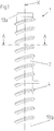
- the concrete pile element 1 shows a concrete pile element 1 according to the invention for forming a concrete screw pile from several such concrete pile elements for a foundation in a side view.
- the concrete pile element 1 has a length of 8 m and a diameter of 55 cm.
- the ends of the concrete pile element 1 are each formed by a half 13a, 13b of a rotary joint (in 1 shown only schematically), which makes it possible to connect several of these concrete pile elements 1 to one another in a form-fitting manner in the longitudinal direction by adjoining one another at the ends and then twisting them relative to one another.
- These rotating coupling halves 13a, 13b are described in detail below.
- the concrete pile element 1 has a cylindrical shank 2 made of concrete, through which a central opening 3 passes in the axial direction.
- a rib 4 is arranged on the outer circumference of the shank 2 essentially over the entire axial extent of the concrete pile element, which rib runs helically around the shank 2 and thereby forms a single-start external thread with a uniform pitch. In the figures 2 and 3 this rib 4 is not shown in section to simplify the illustration.
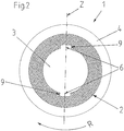
- the boundaries of the central opening 3 form a circular through-bore, seen in cross-section, from which two recesses 6 extend radially outwards, distributed evenly over its circumference, ie each offset by 180° on the circumference.
- the depressions 6 each have one, seen in cross section axis of symmetry Z running in the radial direction, and their lateral boundaries are each formed by a surface 9 extending essentially radially outwards.
- the drive linkage 5 has a cylindrical shaft 10 which, on its outer surface over its entire length and evenly over its circumference, i.e. offset by 180° on the circumference, has two projections 11 running in the axial direction and extending outwards in the radial direction carries, which engage in the radially outwardly extending recesses 6 in the boundaries of the central opening 3.
- the projections 11 of the drive linkage 5 are each essentially trapezoidal in cross-section, with the oblique sides of the trapezoidal shape extending along radial lines running through the center of the drive linkage 5 .
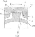
- the drive linkage 5 is then rotated to drive the concrete pile element 1 as intended, it rotates in the central opening 3 until the rotational play is achieved by the projections 11 striking the radially outwardly extending surfaces 9 of the lateral delimitations of the depressions, which are directed counter to the screwing-in direction R of the thread 6 is repealed (see figure 5 ).
- the drive torque is then transmitted from the drive linkage 5 to the concrete pile element 1 by the introduction of compressive forces running essentially perpendicularly to this surface 9 F with the projections 11 of the drive linkage 5 in these surfaces 9.
- the boundaries of the central opening 3 seen in cross-section form in the depressions 6 adjoining the respective lateral boundaries of the respective depression 6 regions 8 in which the radial extent S1, S2 of the central opening 3 decreases uniformly and steplessly in the direction of screwing in the thread R (the radial extent S1 is greater than the radial extent S2, which follows S1 in the direction of screwing in the thread R).
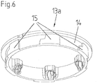
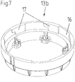
- the figures 6 and 7 13 show perspective views of the two swivel halves 13a, 13b which form the ends of the concrete pile element 1.
- FIG. As can be seen, the first rotary coupling half 13a is designed as a male rotary coupling half (see FIG 6 ).
- the rotary coupling formed with the rotary coupling halves 13a, 13b is a bayonet coupling with six locking points distributed evenly over the circumference of the coupling.
- the rotating coupling halves 13a, 13b are designed at the ends of the concrete pile element 1 and rotationally aligned with respect to the central opening 3 and the helical rib 4 in such a way that an intended coupling situation is possible in which the cross sections of the central openings 3 of two concrete pile elements 1 coupled together as intended are congruent are and whose helical ribs 4 form sections of a common screw thread.
- the procedure for coupling two such concrete pile elements 1 together as intended is as follows: In a first step, a first of the two concrete pile elements is screwed into a substrate using the driving tool 5, preferably in such a way that its free end is formed by the male swivel coupling half 13a.
- the end of the second concrete pile element formed by the female swivel half 13b is then abutted against the free end of the first concrete pile element, which is formed by a first swivel half 13a, in such a way that the longitudinal axes of the concrete pile elements coincide and the insertion ring 14 of the male swivel half 13a is separated from the Receiving ring 16 of the female swivel half 13b is received.
- the cross-sectional contours of the central openings 3 of the two concrete pile elements 1a, 1b are arranged rotated relative to one another by an angle of rotation ⁇ , which is larger or is equal to the angle of rotation, which is required for the intended coupling of the two rotating coupling halves 13a, 13b.
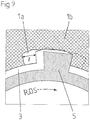
- the central openings 3 of the two concrete pile elements 1a, 1b are penetrated by the driving tool 5 in such a way that the driving tool 5 in the closing direction of rotation DS of the second swivel coupling half 13b, which forms the adjacent end of the second concrete pile 1b, forms a rotational form fit with the boundaries of the central opening 3 of the second concrete pile element 1b and such a form fit with the boundaries of the central opening 3 of the first concrete pile element 1a only occurs after the drive tool 5 has been twisted in the central opening 3 of the first screwed concrete pile element 1a by the twisting angle ⁇ , as is the case in 9 is shown.
- the second concrete pile element 1b is then rotated relative to the first concrete pile element 1a with the drive tool 5 by the twisting angle ⁇ in the closing direction of rotation DS of the second swivel joint half 13b, which forms the adjacent end of the second concrete pile 1b, whereby the two swivel joint halves 13a, 13b are coupled together as intended and the cross-sectional contours of the central openings 3 of the two concrete pile elements 1a, 1b become congruent.
- This situation is in 10 shown.
- the first concrete pile element 1a is completely hidden behind the second concrete pile element 1b in this illustration and is therefore not visible.
- the first concrete pile element 1a and the second concrete pile element 1b are used together with the driving tool 5 is screwed into the ground, with the screwing-in direction R corresponding to the locking rotating direction DS of the second rotating coupling half 13b, which forms the coupled end of the second concrete pile 1b.
- the central openings 3 of both concrete pile elements 1a, 1b are penetrated by the driving tool 5, so that the driving tool 5 forms a rotational form fit in the driving direction R both with the borders of the central opening 3 of the first concrete pile element 1a and with the borders of the central opening 3 of the second concrete pile element 1b.
Landscapes
- Engineering & Computer Science (AREA)
- Structural Engineering (AREA)
- Life Sciences & Earth Sciences (AREA)
- General Life Sciences & Earth Sciences (AREA)
- Mining & Mineral Resources (AREA)
- Paleontology (AREA)
- Civil Engineering (AREA)
- General Engineering & Computer Science (AREA)
- Piles And Underground Anchors (AREA)
Applications Claiming Priority (1)
| Application Number | Priority Date | Filing Date | Title |
|---|---|---|---|
| CH00834/20A CH717618A1 (de) | 2020-07-07 | 2020-07-07 | Betonpfahlelement sowie Verfahren zum Zusammenkuppeln zweier Betonpfahlelemente. |
Publications (1)
| Publication Number | Publication Date |
|---|---|
| EP3936670A1 true EP3936670A1 (fr) | 2022-01-12 |
Family
ID=76623859
Family Applications (1)
| Application Number | Title | Priority Date | Filing Date |
|---|---|---|---|
| EP21179955.6A Withdrawn EP3936670A1 (fr) | 2020-07-07 | 2021-06-17 | Pieu en béton et procédé d'accouplement de deux pieux en béton |
Country Status (2)
| Country | Link |
|---|---|
| EP (1) | EP3936670A1 (fr) |
| CH (1) | CH717618A1 (fr) |
Cited By (3)
| Publication number | Priority date | Publication date | Assignee | Title |
|---|---|---|---|---|
| CN115874621A (zh) * | 2023-01-09 | 2023-03-31 | 江西旋进科技有限公司 | 一种多节螺旋管桩旋进入土的施工方法 |
| EP4223936A1 (fr) * | 2022-02-03 | 2023-08-09 | Centrum Pæle A/S | Pieu de fondation, fondation sur pieu, élément de couplage et procédé d'installation d'un pieu de fondation dans le sol |
| EP4660379A1 (fr) * | 2024-06-07 | 2025-12-10 | Centrum Pæle A/S | Pieu de fondation |
Citations (7)
| Publication number | Priority date | Publication date | Assignee | Title |
|---|---|---|---|---|
| DE1237036B (de) * | 1965-03-11 | 1967-03-23 | Celler Maschf Geb | Steckverbindung fuer Futterrohre, insbesondere fuer den Brunnenbau und Pfahlgruendungen |
| JPS61225422A (ja) * | 1985-03-29 | 1986-10-07 | Asahi Chem Ind Co Ltd | コンクリ−ト杭 |
| EP0253988A1 (fr) * | 1986-07-23 | 1988-01-27 | Delmag-Maschinenfabrik Reinhold Dornfeld GmbH & Co. | Pièce en béton préfabriqué et méthode pour introduire une telle pièce dans le sol |
| CH710018A2 (de) | 2014-08-26 | 2016-02-29 | Alphabeton Ag | Betonschraubpfahl sowie Verfahren zu dessen Herstellung. |
| WO2016029325A1 (fr) | 2014-08-26 | 2016-03-03 | Alphabeton Ag | Procédé pour la fabrication d'un corps en béton ainsi que pieu à vis en béton fabriqué à l'aide de ce procédé |
| KR20190019228A (ko) * | 2017-08-16 | 2019-02-27 | 유영산업(주) | 콘크리트파일용 연결유니트 |
| KR102065742B1 (ko) * | 2019-04-29 | 2020-01-13 | 주식회사 택한 | 강관 파일 연결구 |
Family Cites Families (2)
| Publication number | Priority date | Publication date | Assignee | Title |
|---|---|---|---|---|
| JPS62156421A (ja) * | 1985-12-27 | 1987-07-11 | Mitsuru Honda | スクリユ−杭 |
| JPS62211422A (ja) * | 1986-03-11 | 1987-09-17 | Soichi Abe | Pcらせん杭のねじり貫入法 |
-
2020
- 2020-07-07 CH CH00834/20A patent/CH717618A1/de unknown
-
2021
- 2021-06-17 EP EP21179955.6A patent/EP3936670A1/fr not_active Withdrawn
Patent Citations (7)
| Publication number | Priority date | Publication date | Assignee | Title |
|---|---|---|---|---|
| DE1237036B (de) * | 1965-03-11 | 1967-03-23 | Celler Maschf Geb | Steckverbindung fuer Futterrohre, insbesondere fuer den Brunnenbau und Pfahlgruendungen |
| JPS61225422A (ja) * | 1985-03-29 | 1986-10-07 | Asahi Chem Ind Co Ltd | コンクリ−ト杭 |
| EP0253988A1 (fr) * | 1986-07-23 | 1988-01-27 | Delmag-Maschinenfabrik Reinhold Dornfeld GmbH & Co. | Pièce en béton préfabriqué et méthode pour introduire une telle pièce dans le sol |
| CH710018A2 (de) | 2014-08-26 | 2016-02-29 | Alphabeton Ag | Betonschraubpfahl sowie Verfahren zu dessen Herstellung. |
| WO2016029325A1 (fr) | 2014-08-26 | 2016-03-03 | Alphabeton Ag | Procédé pour la fabrication d'un corps en béton ainsi que pieu à vis en béton fabriqué à l'aide de ce procédé |
| KR20190019228A (ko) * | 2017-08-16 | 2019-02-27 | 유영산업(주) | 콘크리트파일용 연결유니트 |
| KR102065742B1 (ko) * | 2019-04-29 | 2020-01-13 | 주식회사 택한 | 강관 파일 연결구 |
Cited By (4)
| Publication number | Priority date | Publication date | Assignee | Title |
|---|---|---|---|---|
| EP4223936A1 (fr) * | 2022-02-03 | 2023-08-09 | Centrum Pæle A/S | Pieu de fondation, fondation sur pieu, élément de couplage et procédé d'installation d'un pieu de fondation dans le sol |
| CN115874621A (zh) * | 2023-01-09 | 2023-03-31 | 江西旋进科技有限公司 | 一种多节螺旋管桩旋进入土的施工方法 |
| EP4660379A1 (fr) * | 2024-06-07 | 2025-12-10 | Centrum Pæle A/S | Pieu de fondation |
| WO2025252484A1 (fr) * | 2024-06-07 | 2025-12-11 | Centrum Paele A/S | Pieu de fondation |
Also Published As
| Publication number | Publication date |
|---|---|
| CH717618A1 (de) | 2022-01-14 |
Similar Documents
| Publication | Publication Date | Title |
|---|---|---|
| EP2467231B1 (fr) | Procédé de fabrication d'un élément de colonne de direction formant une section d'une colonne de direction | |
| EP3044468B1 (fr) | Hélice pour insert fileté | |
| EP1849956A1 (fr) | Raccord de tuyau pour des éléments de tuyau | |
| EP3936670A1 (fr) | Pieu en béton et procédé d'accouplement de deux pieux en béton | |
| EP2646625B1 (fr) | Élément d'accouplement, notamment pour relier des tiges de boulon d'ancrage | |
| EP2321542A1 (fr) | Agencement d'entraînement pour vis | |
| DE102015211744B4 (de) | Rotationswerkzeug, insbesondere Bohrer, und Schneidkopf für ein solches Rotationswerkzeug | |
| EP2476919B1 (fr) | Vis d'ancrage et procédé de fabrication d'une vis d'ancrage | |
| EP3219442A1 (fr) | Élement d'entrainement d'un couple de rotation sur une cosse a insert filete | |
| EP0391119B1 (fr) | Elément de connexion pour un raccord vissé de boulons d'ancrage à injection auto-forants | |
| EP3205794A1 (fr) | Système de poignée et procédé de montage | |
| DE102023110121B3 (de) | Pfahlkupplung zum zusammenfügen von mehreren teilelementen zu pfählen | |
| EP3480419B1 (fr) | Dispositif formant tarière hélicoïdale et procédé de formation d'un dispositif formant tarière hélicoïdale | |
| EP1829665A1 (fr) | Dispositif de couplage a vis d'extrudeuse | |
| DE102022100210B4 (de) | Zweiteilige Schraubenmutter und Set mit einer solchen Schraubenmutter | |
| EP4249784A1 (fr) | Adaptateur de tuyau | |
| EP1277892B1 (fr) | Manchon pour lier des ronds à béton | |
| EP2483027A1 (fr) | Procédé de fabrication d'une denture intérieure et élément à denture intérieure | |
| CH710018A2 (de) | Betonschraubpfahl sowie Verfahren zu dessen Herstellung. | |
| EP4086426A1 (fr) | Accouplement de tiges d'une tige de tarière | |
| EP4567250B1 (fr) | Tube de forage pour la fabrication d'un trou de coulée tubulaire | |
| EP4212743A1 (fr) | Élément d'ancrage destiné à être ancré dans un puits de forage, ensemble d'ancrage comprenant un tel élément d'ancrage et procédé de fabrication d'un tel ensemble d'ancrage | |
| EP2178428A2 (fr) | Procédé pour fabriquer un arbre d'entrainement | |
| EP1683980B1 (fr) | Elément entraineur à bride pour joint de cardan et arbre articulé | |
| EP4212744A1 (fr) | Unité d'ancrage pour ancrage dans un puits de forage dans un matériau, ensemble d'ancrage comprenant une telle unité d'ancrage et procédé de fabrication d'un tel ensemble d'ancrage |
Legal Events
| Date | Code | Title | Description |
|---|---|---|---|
| PUAI | Public reference made under article 153(3) epc to a published international application that has entered the european phase |
Free format text: ORIGINAL CODE: 0009012 |
|
| STAA | Information on the status of an ep patent application or granted ep patent |
Free format text: STATUS: THE APPLICATION HAS BEEN PUBLISHED |
|
| AK | Designated contracting states |
Kind code of ref document: A1 Designated state(s): AL AT BE BG CH CY CZ DE DK EE ES FI FR GB GR HR HU IE IS IT LI LT LU LV MC MK MT NL NO PL PT RO RS SE SI SK SM TR |
|
| B565 | Issuance of search results under rule 164(2) epc |
Effective date: 20211129 |
|
| RAP1 | Party data changed (applicant data changed or rights of an application transferred) |
Owner name: KIBAG BAULEISTUNGEN AG |
|
| RAP1 | Party data changed (applicant data changed or rights of an application transferred) |
Owner name: CENTRUM PAELE A/S |
|
| STAA | Information on the status of an ep patent application or granted ep patent |
Free format text: STATUS: REQUEST FOR EXAMINATION WAS MADE |
|
| 17P | Request for examination filed |
Effective date: 20220705 |
|
| RBV | Designated contracting states (corrected) |
Designated state(s): AL AT BE BG CH CY CZ DE DK EE ES FI FR GB GR HR HU IE IS IT LI LT LU LV MC MK MT NL NO PL PT RO RS SE SI SK SM TR |
|
| STAA | Information on the status of an ep patent application or granted ep patent |
Free format text: STATUS: EXAMINATION IS IN PROGRESS |
|
| 17Q | First examination report despatched |
Effective date: 20231222 |
|
| STAA | Information on the status of an ep patent application or granted ep patent |
Free format text: STATUS: THE APPLICATION IS DEEMED TO BE WITHDRAWN |
|
| 18D | Application deemed to be withdrawn |
Effective date: 20240423 |