EP3936671A1 - Engin de travail - Google Patents
Engin de travail Download PDFInfo
- Publication number
- EP3936671A1 EP3936671A1 EP19918800.4A EP19918800A EP3936671A1 EP 3936671 A1 EP3936671 A1 EP 3936671A1 EP 19918800 A EP19918800 A EP 19918800A EP 3936671 A1 EP3936671 A1 EP 3936671A1
- Authority
- EP
- European Patent Office
- Prior art keywords
- state
- cautions
- operator
- working machine
- display
- Prior art date
- Legal status (The legal status is an assumption and is not a legal conclusion. Google has not performed a legal analysis and makes no representation as to the accuracy of the status listed.)
- Granted
Links
Images


Classifications
-
- E—FIXED CONSTRUCTIONS
- E02—HYDRAULIC ENGINEERING; FOUNDATIONS; SOIL SHIFTING
- E02F—DREDGING; SOIL-SHIFTING
- E02F9/00—Component parts of dredgers or soil-shifting machines, not restricted to one of the kinds covered by groups E02F3/00 - E02F7/00
- E02F9/24—Safety devices, e.g. for preventing overload
-
- E—FIXED CONSTRUCTIONS
- E02—HYDRAULIC ENGINEERING; FOUNDATIONS; SOIL SHIFTING
- E02F—DREDGING; SOIL-SHIFTING
- E02F9/00—Component parts of dredgers or soil-shifting machines, not restricted to one of the kinds covered by groups E02F3/00 - E02F7/00
- E02F9/16—Cabins, platforms, or the like, for drivers
-
- E—FIXED CONSTRUCTIONS
- E02—HYDRAULIC ENGINEERING; FOUNDATIONS; SOIL SHIFTING
- E02F—DREDGING; SOIL-SHIFTING
- E02F9/00—Component parts of dredgers or soil-shifting machines, not restricted to one of the kinds covered by groups E02F3/00 - E02F7/00
- E02F9/26—Indicating devices
-
- B—PERFORMING OPERATIONS; TRANSPORTING
- B60—VEHICLES IN GENERAL
- B60K—ARRANGEMENT OR MOUNTING OF PROPULSION UNITS OR OF TRANSMISSIONS IN VEHICLES; ARRANGEMENT OR MOUNTING OF PLURAL DIVERSE PRIME-MOVERS IN VEHICLES; AUXILIARY DRIVES FOR VEHICLES; INSTRUMENTATION OR DASHBOARDS FOR VEHICLES; ARRANGEMENTS IN CONNECTION WITH COOLING, AIR INTAKE, GAS EXHAUST OR FUEL SUPPLY OF PROPULSION UNITS IN VEHICLES
- B60K26/00—Arrangement or mounting of propulsion-unit control devices in vehicles
- B60K26/02—Arrangement or mounting of propulsion-unit control devices in vehicles of initiating means or elements
-
- B—PERFORMING OPERATIONS; TRANSPORTING
- B60—VEHICLES IN GENERAL
- B60K—ARRANGEMENT OR MOUNTING OF PROPULSION UNITS OR OF TRANSMISSIONS IN VEHICLES; ARRANGEMENT OR MOUNTING OF PLURAL DIVERSE PRIME-MOVERS IN VEHICLES; AUXILIARY DRIVES FOR VEHICLES; INSTRUMENTATION OR DASHBOARDS FOR VEHICLES; ARRANGEMENTS IN CONNECTION WITH COOLING, AIR INTAKE, GAS EXHAUST OR FUEL SUPPLY OF PROPULSION UNITS IN VEHICLES
- B60K35/00—Instruments specially adapted for vehicles; Arrangement of instruments in or on vehicles
- B60K35/10—Input arrangements, i.e. from user to vehicle, associated with vehicle functions or specially adapted therefor
-
- B—PERFORMING OPERATIONS; TRANSPORTING
- B60—VEHICLES IN GENERAL
- B60K—ARRANGEMENT OR MOUNTING OF PROPULSION UNITS OR OF TRANSMISSIONS IN VEHICLES; ARRANGEMENT OR MOUNTING OF PLURAL DIVERSE PRIME-MOVERS IN VEHICLES; AUXILIARY DRIVES FOR VEHICLES; INSTRUMENTATION OR DASHBOARDS FOR VEHICLES; ARRANGEMENTS IN CONNECTION WITH COOLING, AIR INTAKE, GAS EXHAUST OR FUEL SUPPLY OF PROPULSION UNITS IN VEHICLES
- B60K35/00—Instruments specially adapted for vehicles; Arrangement of instruments in or on vehicles
- B60K35/20—Output arrangements, i.e. from vehicle to user, associated with vehicle functions or specially adapted therefor
- B60K35/28—Output arrangements, i.e. from vehicle to user, associated with vehicle functions or specially adapted therefor characterised by the type of the output information, e.g. video entertainment or vehicle dynamics information; characterised by the purpose of the output information, e.g. for attracting the attention of the driver
-
- B—PERFORMING OPERATIONS; TRANSPORTING
- B60—VEHICLES IN GENERAL
- B60K—ARRANGEMENT OR MOUNTING OF PROPULSION UNITS OR OF TRANSMISSIONS IN VEHICLES; ARRANGEMENT OR MOUNTING OF PLURAL DIVERSE PRIME-MOVERS IN VEHICLES; AUXILIARY DRIVES FOR VEHICLES; INSTRUMENTATION OR DASHBOARDS FOR VEHICLES; ARRANGEMENTS IN CONNECTION WITH COOLING, AIR INTAKE, GAS EXHAUST OR FUEL SUPPLY OF PROPULSION UNITS IN VEHICLES
- B60K35/00—Instruments specially adapted for vehicles; Arrangement of instruments in or on vehicles
- B60K35/20—Output arrangements, i.e. from vehicle to user, associated with vehicle functions or specially adapted therefor
- B60K35/29—Instruments characterised by the way in which information is handled, e.g. showing information on plural displays or prioritising information according to driving conditions
-
- B—PERFORMING OPERATIONS; TRANSPORTING
- B60—VEHICLES IN GENERAL
- B60K—ARRANGEMENT OR MOUNTING OF PROPULSION UNITS OR OF TRANSMISSIONS IN VEHICLES; ARRANGEMENT OR MOUNTING OF PLURAL DIVERSE PRIME-MOVERS IN VEHICLES; AUXILIARY DRIVES FOR VEHICLES; INSTRUMENTATION OR DASHBOARDS FOR VEHICLES; ARRANGEMENTS IN CONNECTION WITH COOLING, AIR INTAKE, GAS EXHAUST OR FUEL SUPPLY OF PROPULSION UNITS IN VEHICLES
- B60K35/00—Instruments specially adapted for vehicles; Arrangement of instruments in or on vehicles
- B60K35/80—Arrangements for controlling instruments
- B60K35/81—Arrangements for controlling instruments for controlling displays
-
- B—PERFORMING OPERATIONS; TRANSPORTING
- B60—VEHICLES IN GENERAL
- B60K—ARRANGEMENT OR MOUNTING OF PROPULSION UNITS OR OF TRANSMISSIONS IN VEHICLES; ARRANGEMENT OR MOUNTING OF PLURAL DIVERSE PRIME-MOVERS IN VEHICLES; AUXILIARY DRIVES FOR VEHICLES; INSTRUMENTATION OR DASHBOARDS FOR VEHICLES; ARRANGEMENTS IN CONNECTION WITH COOLING, AIR INTAKE, GAS EXHAUST OR FUEL SUPPLY OF PROPULSION UNITS IN VEHICLES
- B60K2360/00—Indexing scheme associated with groups B60K35/00 or B60K37/00 relating to details of instruments or dashboards
- B60K2360/16—Type of output information
- B60K2360/167—Vehicle dynamics information
-
- B—PERFORMING OPERATIONS; TRANSPORTING
- B60—VEHICLES IN GENERAL
- B60K—ARRANGEMENT OR MOUNTING OF PROPULSION UNITS OR OF TRANSMISSIONS IN VEHICLES; ARRANGEMENT OR MOUNTING OF PLURAL DIVERSE PRIME-MOVERS IN VEHICLES; AUXILIARY DRIVES FOR VEHICLES; INSTRUMENTATION OR DASHBOARDS FOR VEHICLES; ARRANGEMENTS IN CONNECTION WITH COOLING, AIR INTAKE, GAS EXHAUST OR FUEL SUPPLY OF PROPULSION UNITS IN VEHICLES
- B60K2360/00—Indexing scheme associated with groups B60K35/00 or B60K37/00 relating to details of instruments or dashboards
- B60K2360/16—Type of output information
- B60K2360/168—Target or limit values
-
- B—PERFORMING OPERATIONS; TRANSPORTING
- B60—VEHICLES IN GENERAL
- B60K—ARRANGEMENT OR MOUNTING OF PROPULSION UNITS OR OF TRANSMISSIONS IN VEHICLES; ARRANGEMENT OR MOUNTING OF PLURAL DIVERSE PRIME-MOVERS IN VEHICLES; AUXILIARY DRIVES FOR VEHICLES; INSTRUMENTATION OR DASHBOARDS FOR VEHICLES; ARRANGEMENTS IN CONNECTION WITH COOLING, AIR INTAKE, GAS EXHAUST OR FUEL SUPPLY OF PROPULSION UNITS IN VEHICLES
- B60K2360/00—Indexing scheme associated with groups B60K35/00 or B60K37/00 relating to details of instruments or dashboards
- B60K2360/16—Type of output information
- B60K2360/178—Warnings
-
- B—PERFORMING OPERATIONS; TRANSPORTING
- B60—VEHICLES IN GENERAL
- B60K—ARRANGEMENT OR MOUNTING OF PROPULSION UNITS OR OF TRANSMISSIONS IN VEHICLES; ARRANGEMENT OR MOUNTING OF PLURAL DIVERSE PRIME-MOVERS IN VEHICLES; AUXILIARY DRIVES FOR VEHICLES; INSTRUMENTATION OR DASHBOARDS FOR VEHICLES; ARRANGEMENTS IN CONNECTION WITH COOLING, AIR INTAKE, GAS EXHAUST OR FUEL SUPPLY OF PROPULSION UNITS IN VEHICLES
- B60K2360/00—Indexing scheme associated with groups B60K35/00 or B60K37/00 relating to details of instruments or dashboards
- B60K2360/18—Information management
- B60K2360/186—Displaying information according to relevancy
- B60K2360/1876—Displaying information according to relevancy according to vehicle situations
-
- B—PERFORMING OPERATIONS; TRANSPORTING
- B60—VEHICLES IN GENERAL
- B60K—ARRANGEMENT OR MOUNTING OF PROPULSION UNITS OR OF TRANSMISSIONS IN VEHICLES; ARRANGEMENT OR MOUNTING OF PLURAL DIVERSE PRIME-MOVERS IN VEHICLES; AUXILIARY DRIVES FOR VEHICLES; INSTRUMENTATION OR DASHBOARDS FOR VEHICLES; ARRANGEMENTS IN CONNECTION WITH COOLING, AIR INTAKE, GAS EXHAUST OR FUEL SUPPLY OF PROPULSION UNITS IN VEHICLES
- B60K35/00—Instruments specially adapted for vehicles; Arrangement of instruments in or on vehicles
- B60K35/20—Output arrangements, i.e. from vehicle to user, associated with vehicle functions or specially adapted therefor
- B60K35/21—Output arrangements, i.e. from vehicle to user, associated with vehicle functions or specially adapted therefor using visual output, e.g. blinking lights or matrix displays
- B60K35/23—Head-up displays [HUD]
-
- E—FIXED CONSTRUCTIONS
- E02—HYDRAULIC ENGINEERING; FOUNDATIONS; SOIL SHIFTING
- E02F—DREDGING; SOIL-SHIFTING
- E02F3/00—Dredgers; Soil-shifting machines
- E02F3/04—Dredgers; Soil-shifting machines mechanically-driven
- E02F3/28—Dredgers; Soil-shifting machines mechanically-driven with digging tools mounted on a dipper- or bucket-arm, i.e. there is either one arm or a pair of arms, e.g. dippers, buckets
- E02F3/30—Dredgers; Soil-shifting machines mechanically-driven with digging tools mounted on a dipper- or bucket-arm, i.e. there is either one arm or a pair of arms, e.g. dippers, buckets with a dipper-arm pivoted on a cantilever beam, i.e. boom
- E02F3/32—Dredgers; Soil-shifting machines mechanically-driven with digging tools mounted on a dipper- or bucket-arm, i.e. there is either one arm or a pair of arms, e.g. dippers, buckets with a dipper-arm pivoted on a cantilever beam, i.e. boom working downwardly and towards the machine, e.g. with backhoes
-
- G—PHYSICS
- G02—OPTICS
- G02B—OPTICAL ELEMENTS, SYSTEMS OR APPARATUS
- G02B27/00—Optical systems or apparatus not provided for by any of the groups G02B1/00 - G02B26/00, G02B30/00
- G02B27/01—Head-up displays
- G02B27/0101—Head-up displays characterised by optical features
- G02B2027/0141—Head-up displays characterised by optical features characterised by the informative content of the display
-
- G—PHYSICS
- G02—OPTICS
- G02B—OPTICAL ELEMENTS, SYSTEMS OR APPARATUS
- G02B27/00—Optical systems or apparatus not provided for by any of the groups G02B1/00 - G02B26/00, G02B30/00
- G02B27/01—Head-up displays
- G02B27/0101—Head-up displays characterised by optical features
Definitions
- the present invention relates to a working machine.
- Patent Literature 1 discloses a working machine in which a decal is attached to a window glass of a cab. This decal is used as a so-called "caution label" for, e.g., alerting an operator to various cautions for operating the working machine.
- Patent Literature 1 Japanese Patent Application Laid-Open (Translation of PCT Application) No. 2013-533406
- the present invention has been developed in view of the actual circumstances noted above and an object of the present invention resides in providing a working machine that makes it possible to alert its operator to cautions properly without obstructing the view of the operator.
- the present invention resides in a working machine provided with a cab for its operator to ride in.
- the working machine is characterized by including a projection device that projects image light to form an image of cautions to an operator who operates the working machine, a display unit that displays image light projected by the projection device, state detection element to detect a state of the working machine, and a controller that controls the projection device so that a manner of displaying the cautions on the display unit will change depending on the state of the working machine detected by the state detection element.
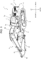
- FIG. 1 is a perspective view of a hydraulic excavator 1 which is a representative example of a working machine pertaining to the present invention.
- FIG. 2 is a perspective view of a cab 7 that viewed from the doorway side. Note that front, back, left and right mentioned herein are based on the viewpoint of an operator who rides in the hydraulic excavator 1 and operates it, unless otherwise noted.
- the hydraulic excavator 1 includes an undercarriage 2 and an upperstructure 3 supported on the undercarriage 2.
- the undercarriage 2 is equipped with a pair of left and right crawlers 9. Driving force of a traction motor (omitted from depiction) is transmitted to the pair of crawlers 9 and the crawlers rotate.
- the undercarriage 2 may be equipped with wheels instead of the crawlers 9.
- the upperstructure 3 is supported on the undercarriage 2 so as to be swingable by a swing motor (omitted from depiction).
- the upperstructure 3 includes, principally, a swing frame 5 serving as a base, a front working device 4 (a working device) installed in the front center of the swing frame 5 so as to be turnable in a vertical direction, a cab (with a driver's seat) 7 placed at left in a front part of the swing frame 5, a counterweight 6 placed in a rear part of the swing frame 5, and a battery 8 (see FIG. 3 ).
- the front working device 4 includes a boom 4a supported on the upperstructure 3 so as to be raised and lowered, an arm 4b swingably supported on a forward end of the boom 4a, a bucket 4c swingably supported on a forward end of the arm 4b, and hydraulic cylinders (actuators) 4d to 4f for driving the boom 4a, arm 4b, and bucket 4c.
- the counterweight 6 is a heavy object for weight balancing with the front working device 4.
- the battery 8 stores electric power generated by a generator (omitted from depiction) which is driven by an engine (omitted from depiction) and supplies stored electric power to respective parts of the hydraulic excavator 1.
- the cab 7 has a box form with an internal space formed for an operator who operates the hydraulic excavator 1 to ride in. As depicted in FIG. 1 and FIG. 2 , the cab 7 is provided with a front window 7a, a left side window 7b, a right side window 7c, and a rear window 7d for the operator who rides in the internal space to see outside the cab 7.
- a doorway for the operator to enter and exit the cab 7 is provided in the left side of the cab 7.
- a seat 10 for the operator to sit on and operating devices (steering, pedals, levers, switches, etc.) that will be operated by the operator sitting on the seat 10.
- the operating devices By operating the operating devices by the operator who rides in the cab 7, the undercarriage 2 travels, the upperstructure 3 swings, and the front working device 4 operates.
- the operating devices include a travel control lever 11, a front control lever 12, a gate lock lever (a lock operating element) 13, a push button 14, and a key switch 15 (see FIG. 3 ).
- the gate lock lever 13, the push button 14, and the key switch 15 are examples of state detection element to detect a state of the hydraulic excavator 1.
- the travel control lever 11 controls the rotational speed and rotational direction of the pair of crawlers 9. That is, by operating the travel control lever 11 by the operator, the undercarriage 2 moves forward and backward and turns.
- the front control lever 12 controls extension and shortening of the hydraulic cylinders 4d to 4f. That is, by operating the front control lever 12 by the operator, the front working device 4 operates.
- the gate lock lever 13 is configured to enable switching between a locked state in which operation of the hydraulic excavator 1 (i.e., the traction motor, the swing motor, and the hydraulic cylinders 4d to 4f) is disabled and an unlocked state in which operation of the hydraulic excavator 1 is enabled.
- the gate lock lever 13, for instance, outputs an operation signal to a controller 20 in a case where it is in the unlocked state.
- the gate lock lever 13 is, for example, placed between the doorway of the cab 7 and the seat 10.
- the gate lock lever 13 is set in the unlocked state in a case where it is pulled down to a position as in FIG. 2 .
- the gate lock lever 13 projects into a passage between the doorway of the cab 7 and seat 10 and prevents the operator from getting on and off the cab 7.
- the gate lock lever 13 is set in the locked state in a case where it is pulled up from the position as in FIG. 2 .
- the gate lock lever 13 gets out of the passage between the doorway of the cab 7 and seat 10 and does not prevent the operator from getting on and off the cab 7.
- the push button 14 is a momentary switch that is set in an ON state only while it is pressed (operated) by the operator and set in an OFF state in a case where the operator stops pressing.
- the bush button 14, for instance, outputs an operation signal to the controller 20 only while it is in the ON state.
- the front control lever 12 is provided with the push button 14 in its top end; however, the position where the push button 14 is placed is not limited to this position.
- the key switch 15 is a switch to start and stop the engine. For instance, inserting a key in the key switch 15 and rotating it up to a first position causes an alternator to rotate and the engine to start (ON state). On the other hand, rotating the key up to a second direction causes the engine to stop (OFF state). Note that the key switch 15 may be configured to make it impossible to rotate the key up to the first position in a case where the gate lock lever is not set in the locked state.
- the key switch 15 in a case where the key switch 15 is in the ON state, electric power stored in the battery 8 is supplied to a projection device 16 and the controller 20. On the other hand, in a case where the key switch 15 is in the OFF state, no electric power is supplied to the projection device 16 and the controller 20. Furthermore, the key switch 15 may be configured to make it possible to rotate the key to a third position, so that electric power will be supplied to the projection device 16 and the controller 20 while the engine remains deactivated (battery driving state).
- the projection device 16 and a combiner (display unit) 17 are installed in the internal space of the cab 7, the projection device 16 and a combiner (display unit) 17 are installed.
- the projection device 16 and the combiner 17 constitute an HUD (Head-up Display) unit to display information that should be conveyed to the operator as alerts.
- HUD Head-up Display
- the projection device 16 projects image light to form an image (a still or moving image) on the combiner 17 according to control by the controller 20. That is, the projection device 16 projects the image light to be incident at a predetermined angle on the combiner 17. Because a concrete structure of the projection device 16 is already known well, its detailed description is omitted.
- the combiner 17 is a transparent plate-shaped (filmy) member and it is attached to a window of the cab 7.
- the combiner 17 pertaining to the present embodiment is attached to a portion of the right side window 7c.
- the position where the combiner 17 is placed is not so limited and it may be placed in the front window 7a, the left side window 7b, or the rear window 7d.
- the combiner 17 is configured to be attached to an existing window glass; a window glass having functionality of the combiner 17 may be installed to the cab 7. That is, the display unit may be a window glass.
- the combiner 17 is a so-called "half mirror" that transmits light incident on the right side window 7c from outside the cab 7 and reflects the image light projected by projection device 16 to a position of eyes of the operator sitting on the seat 10. In other words, the operator sitting on the seat 10 can see outside the cab 7 through the combiner 17 and, also, an image formed by the image light projected by projection device 16 appears to be displayed on the combiner 17.
- the HUD unit configured as mentioned above makes the operator sitting on the seat 10 see a virtual image.
- the HUD unit can set the seeing distance of an image displayed on the combiner 17 to infinity. That is, the operator sitting on the seat 10 can see conditions surrounding the hydraulic excavator 1 and an image displayed on the combiner 17 without changing the focal length to a great extent.
- the HDU unit pertaining to the present embodiment displays, for example, cautions 18 to which the operator operating the hydraulic excavator 1 should be alerted.
- the cautions are things that the operator should be made be aware of before starting to operate the hydraulic excavator 1.
- a concrete example of the cautions 18 is, for example, an image (see FIG. 5 ) symbolizing that abruptly starting to swing the upperstructure 3 may mow down a person surrounding the excavator.
- cautions 18 to be displayed on the combiner 17 are not limited to such image.
- Various cautions can be displayed to represent that the operator should wear a seat belt, that the opened front window 7a could fall, that the hydraulic excavator 1 could fall on sloping ground, that an electric shock could occur if the front working device 4 touched an electrical wire, and so on.
- a decal 19 is attached to a portion inside the cab 7.
- the decal 19 contains the same contents as the cautions 18 to be displayed on the combiner 17.
- the decal 19 pertaining to the present embodiment is attached to a wall behind the seat 10 and under the rear window 7d.
- the position where the decal 19 is attached to is not limited to this position; desirably, the decal 19 should be attached to a position where it does not obstruct the view of the operator (e.g., a position other than the windows 7a to 7d).
- FIG. 3 is a block diagram of the hydraulic excavator 1.
- the hydraulic excavator 1 includes the controller 20 that controls the HDU unit.
- the controller 20 controls the projection device 16 so that a manner of displaying the cautions 18 on the combiner 17 will change depending on the states of the gate lock lever 13, push button 14, and key switch 15.
- the controller 20 includes a CPU (Central Processing Unit) 21, a ROM (Read Only Memory) 22, and a RAM (Random Access Memory) 23.
- the controller 20 implements processing which will be described later in such a way that the CPU 21 reads and executes a program code stored in the ROM22.
- the RAM 23 is used as a work area while the CPU 21 executes a program.
- controller 20 may be implemented by hardware such as ASIC (Application Specific Integrated Circuit) and FPGA (Field-Programmable Gate Array).
- ASIC Application Specific Integrated Circuit
- FPGA Field-Programmable Gate Array
- FIG. 4 is a state transition diagram representing a relationship between the states of the hydraulic excavator 1 and the display status of the cautions 18.
- the controller 20 does not display the cautions 18 on the combiner 17 (display status A). Also, in a case where the key switch 15 is in the OFF state, the cautions 18 remain hidden (the display manner remains unchanged) even if the operator operates the gate lock lever 13 and the push button 14.
- the controller 20 displays the cautions 18 on the combiner 17 (display status B).
- the controller 20 hides the cautions 18 displayed on the combiner 17 (display status C). Furthermore, in a case where the push button 14 is switched from the ON state to the OFF state (S13) with the key switch 15 remaining in the ON state and the gate lock lever 13 remaining in the locked state, the controller 20 displays the cautions on the combiner 17 again (display status B).
- the controller 20 displays the cautions 18; and while the push button 14 is pressed, the controller hides the cautions 18. In other words, the controller 20 hides the cautions 18 temporarily as long as the push button is pressed even with the gate lock lever 13 remains in the locked state.
- the controller 20 hides the cautions 18 displayed on the combiner 17 (display status D). Furthermore, in a case where the gate lock lever 13 is switched from the unlocked state to the locked state (S15) with the key switch 15 remaining in the ON state and the push button 14 remaining in the OFF state, the controller 20 displays the cautions 18 on the combiner 17 (display status B) .
- the controller 20 continues to hide the cautions 18 (display status C). That is, the operator can switch the display status of the cautions 18 by the push button 14 in a case where the gate lock lever 13 is in the locked state, but cannot switch it by the push button 14 in a case where the gate lock lever 13 is in the unlocked state.
- the key switch 15 is switched from the ON state to the OFF state (S18) with the gate lock lever 13 remaining in the locked state and the push button 14 remaining in the OFF state, the controller 20 hides the cautions 18 displayed on the combiner 17 (display status A).
- the controller 20 continues to hide the cautions 18 (display status A).
- the controller 20 continues to hide the cautions 18 (display status A).
- the cautions 18 are displayed on the right side window 7c in a case where the gate lock lever 13 is in the locked state. This allows to alert the operator to the cautions properly before starting to operate the hydraulic excavator 1. Besides, the cautions 18 are hidden in a case where the gate lock lever 13 is in the unlocked state. This enables the operator to operate the hydraulic excavator 1 safely while checking surrounding conditions since there is nothing to obstruct the view of the operator.
- switching can be made between displaying and hiding the cautions 18 by the push button 14 in a case where the gate lock lever 13 is in the locked state. This enables the operator to check outside conditions by pressing the push button 14 without the operator's view being obstructed.
- the push button 14 is a momentary switch, it is possible to prevent that the cautions 18 remain hidden after the operator presses the push button 14 to check outside conditions.
- the push button 14 may be an alternate switch that can switch between ON and OFF states each time the operator presses it.
- the projection device 16 cannot display the cautions 18 while it is not supplied with electric power from the batter 8. Therefore, as in the foregoing embodiment, by attaching the decal 19 having the same contents as the cautions 18 to be displayed on the combiner 17 to the cab 7, it is possible to alert the operator to the cautions 18 even if the key switch 15 is in the OFF state. Furthermore, by attaching the decal 19 to a place other than the windows 7a to 7d, it is avoided to obstruct the view of the operator.
- FIG. 5 is a diagram representing an example of displaying, in a large size, the cautions 18 in the center of the combiner 17.
- FIG. 6 is a diagram representing an example of displaying, in a small size, the cautions 18 in a corner of the combiner 17.
- the controller 20 may display, in a large size, the cautions 18 in the center of the combiner 17 during display status B, as presented in FIG. 5 .
- the controller 20 may display, in a small size, the cautions 18 in a corner of the combiner 17 during display status C or D, as presented in FIG. 6 .
- the second display manner is any one or a combination of hiding the cautions 18, displaying smaller than displayed in the first display manner, and displaying near the edges of a window relative to the display position in the first display manner.
- the second display manner may be setting transmittance higher than in the first display manner, setting saturation lower than in the first display manner, and setting brightness higher than in the first display manner among others.
- the second display manner may be a display manner in which the displayed cautions are more likely not to obstruct the view of the operator than in the first display manner.
- the controller 20 may display the cautions 18 as presented in FIG. 6 during display status C or may hide the cautions 18 during display status D.
- timing of switching from display status B to display status C or D may differ.
- the controller 20 may immediately switch the display manner of the cautions 18 to another manner.
- the controller 20 may switch the display manner of the cautions 18 to another manner upon elapse of a predetermined time (e.g., 5 seconds).
- state detection element is not limited to the gate lock lever 13, the push button 14, and the key switch 15.
- a tilting angle sensor that detects the tilting angle of the hydraulic excavator 1 with respect to a horizontal plane or a front window sensor that detects the front window 7a opening may be taken as a state detection element.
- cautions 18 that are displayed at the same time on the combiner 17 are not limited to one thereof. That is, the controller 20 may display multiple cautions 18 next to each other on the combiner 17. Besides, the controller 20 may switch one of the cautions 18 to be displayed on the combiner 17 to another one according to the state of the hydraulic excavator 1 that is detected by the state detection element.
- the controller may display one of cautions that urge the operator to wear a seat belt on the combiner 17 immediately after the key switch 15 is switched from the OFF state to the ON state. Also, the controller may display one of the cautions 18 as presented in FIG. 5 on the combiner 17 upon elapse of a predetermined time after the key switch 15 is switched to the ON state.
- the controller 20 may display on the combiner 17 cautions alerting that the hydraulic excavator 1 could fall on sloping ground in a case where the tilting angle that is detected by the tilting angle sensor is larger than or equal to a threshold.
- the controller 20 may display on the combiner 17 cautions alerting that the opened front window 7a could fall in a case where the front window 7a opening has been detected by the front window sensor.
- the controller 20 may reduce the amount of the image light that is projected from the projection device 16 in a case where the key switch 115 is in the battery driving state, as compared with that amount in a case where the key switch 15 is in the ON state.
- a concrete example of the working machine is not limited to the hydraulic excavator 1 and may be a work vehicle such as a dump truck, a motor grader, or a wheel loader or a fixed-type machine that operates, fixed to a post.
Landscapes
- Engineering & Computer Science (AREA)
- Chemical & Material Sciences (AREA)
- Combustion & Propulsion (AREA)
- Transportation (AREA)
- Mechanical Engineering (AREA)
- Mining & Mineral Resources (AREA)
- Civil Engineering (AREA)
- General Engineering & Computer Science (AREA)
- Structural Engineering (AREA)
- Component Parts Of Construction Machinery (AREA)
Applications Claiming Priority (2)
| Application Number | Priority Date | Filing Date | Title |
|---|---|---|---|
| JP2019042923A JP7012038B2 (ja) | 2019-03-08 | 2019-03-08 | 作業機械 |
| PCT/JP2019/048445 WO2020183829A1 (fr) | 2019-03-08 | 2019-12-11 | Engin de travail |
Publications (3)
| Publication Number | Publication Date |
|---|---|
| EP3936671A1 true EP3936671A1 (fr) | 2022-01-12 |
| EP3936671A4 EP3936671A4 (fr) | 2022-12-07 |
| EP3936671B1 EP3936671B1 (fr) | 2026-02-11 |
Family
ID=72355470
Family Applications (1)
| Application Number | Title | Priority Date | Filing Date |
|---|---|---|---|
| EP19918800.4A Active EP3936671B1 (fr) | 2019-03-08 | 2019-12-11 | Engin de travail |
Country Status (6)
| Country | Link |
|---|---|
| US (1) | US11952750B2 (fr) |
| EP (1) | EP3936671B1 (fr) |
| JP (1) | JP7012038B2 (fr) |
| KR (1) | KR102494287B1 (fr) |
| CN (1) | CN112639216B (fr) |
| WO (1) | WO2020183829A1 (fr) |
Families Citing this family (2)
| Publication number | Priority date | Publication date | Assignee | Title |
|---|---|---|---|---|
| JP7510895B2 (ja) * | 2021-02-16 | 2024-07-04 | 株式会社小松製作所 | 作業機械の表示システム |
| WO2023122742A1 (fr) * | 2021-12-22 | 2023-06-29 | Clark Equipment Company | Commande de multiples machines électriques |
Family Cites Families (16)
| Publication number | Priority date | Publication date | Assignee | Title |
|---|---|---|---|---|
| JP4010255B2 (ja) * | 2003-02-07 | 2007-11-21 | コベルコ建機株式会社 | 建設機械の制御装置 |
| KR100702180B1 (ko) * | 2005-08-11 | 2007-04-02 | 볼보 컨스트럭션 이키프먼트 홀딩 스웨덴 에이비 | 건설기계용 운전자 진동 모니터링 장치 |
| JP4713600B2 (ja) * | 2008-01-25 | 2011-06-29 | 住友建機株式会社 | 建設機械用表示システム |
| WO2012015078A1 (fr) | 2010-07-28 | 2012-02-02 | 볼보 컨스트럭션 이큅먼트 에이비 | Appareil de fixation de la vitre arrière d'une cabine de conducteur sur un engin de construction |
| JP5841008B2 (ja) * | 2012-05-28 | 2016-01-06 | ヤンマー株式会社 | 旋回作業車 |
| CN102852170A (zh) * | 2012-08-27 | 2013-01-02 | 泰州市华骏机械设备制造有限公司 | 一种具有辅助视像系统的挖掘机 |
| JP6102628B2 (ja) * | 2013-08-09 | 2017-03-29 | アイシン・エィ・ダブリュ株式会社 | ヘッドアップディスプレイ装置 |
| JP6308923B2 (ja) * | 2014-09-18 | 2018-04-11 | 住友建機株式会社 | 建設機械 |
| CN107921870A (zh) * | 2015-09-10 | 2018-04-17 | 富士胶片株式会社 | 投影型显示装置及投影控制方法 |
| CN108027515A (zh) * | 2015-09-25 | 2018-05-11 | 富士胶片株式会社 | 投影型显示装置及投影控制方法 |
| JP6361986B2 (ja) * | 2016-05-30 | 2018-07-25 | マツダ株式会社 | 車両用表示装置 |
| JP6808377B2 (ja) * | 2016-06-27 | 2021-01-06 | 住友建機株式会社 | ショベルの表示装置 |
| KR101899981B1 (ko) * | 2016-12-02 | 2018-09-19 | 엘지전자 주식회사 | 차량용 헤드 업 디스플레이 |
| CN110099818A (zh) * | 2016-12-21 | 2019-08-06 | 富士胶片株式会社 | 投影型显示装置、投影型显示装置的控制方法、投影型显示装置的控制程序 |
| JP6630855B2 (ja) | 2017-01-10 | 2020-01-15 | 富士フイルム株式会社 | 投写型表示装置、投写型表示装置の制御方法、投写型表示装置の制御プログラム |
| JP7039983B2 (ja) * | 2017-12-13 | 2022-03-23 | コベルコ建機株式会社 | 建設機械用の注意喚起装置 |
-
2019
- 2019-03-08 JP JP2019042923A patent/JP7012038B2/ja active Active
- 2019-12-11 WO PCT/JP2019/048445 patent/WO2020183829A1/fr not_active Ceased
- 2019-12-11 EP EP19918800.4A patent/EP3936671B1/fr active Active
- 2019-12-11 KR KR1020217004726A patent/KR102494287B1/ko active Active
- 2019-12-11 US US17/272,692 patent/US11952750B2/en active Active
- 2019-12-11 CN CN201980055494.4A patent/CN112639216B/zh active Active
Also Published As
| Publication number | Publication date |
|---|---|
| KR102494287B1 (ko) | 2023-02-06 |
| WO2020183829A1 (fr) | 2020-09-17 |
| US11952750B2 (en) | 2024-04-09 |
| JP7012038B2 (ja) | 2022-01-27 |
| JP2020143559A (ja) | 2020-09-10 |
| US20210340732A1 (en) | 2021-11-04 |
| EP3936671A4 (fr) | 2022-12-07 |
| KR20210031743A (ko) | 2021-03-22 |
| CN112639216A (zh) | 2021-04-09 |
| CN112639216B (zh) | 2022-12-16 |
| EP3936671B1 (fr) | 2026-02-11 |
Similar Documents
| Publication | Publication Date | Title |
|---|---|---|
| JP7171436B2 (ja) | 作業機械用周辺監視システム、表示装置 | |
| CN113748247B (zh) | 挖土机、作业现场的安全装备确认系统 | |
| JP7358070B2 (ja) | ショベル | |
| JP2004203126A (ja) | 車両用周辺監視装置 | |
| EP3522133A1 (fr) | Système et procédé de surveillance de proximité de véhicule de chantier | |
| CN107075840A (zh) | 作业机械的周边监视装置以及作业机械的周边监视方法 | |
| KR102088787B1 (ko) | 작업 차량 및 작업 차량의 제어 방법 | |
| EP3936671B1 (fr) | Engin de travail | |
| EP3832035B1 (fr) | Pelleteuse hydraulique | |
| KR20230085909A (ko) | 작업 차량 | |
| JP2002371595A (ja) | 建設機械 | |
| CN116490402A (zh) | 工程机械 | |
| JP4567914B2 (ja) | 建設機械 | |
| CN117248592A (zh) | 作业机械的控制方法、作业机械用控制程序、作业机械用控制系统以及作业机械 | |
| US20180363273A1 (en) | Work vehicle | |
| JP2001140286A (ja) | 建設機械の監視カメラシステム | |
| EP4215676A1 (fr) | Engin de chantier | |
| JP6547077B2 (ja) | 投写型表示装置、投写型表示装置の制御方法、投写型表示装置の制御プログラム | |
| JP2010043419A (ja) | 自走式作業機械の表示装置 | |
| KR20240040814A (ko) | 작업 기계의 기동 시스템, 작업 기계의 기동 방법 및 작업 기계 | |
| JP2022146687A (ja) | ショベル | |
| EP4737653A1 (fr) | Engin et système de travail | |
| US20240401308A1 (en) | Display system for work machine and display method for work machine | |
| JP2025068502A (ja) | 作業機械および作業システム | |
| JP2019116780A (ja) | 建設機械の表示システム |
Legal Events
| Date | Code | Title | Description |
|---|---|---|---|
| STAA | Information on the status of an ep patent application or granted ep patent |
Free format text: STATUS: THE INTERNATIONAL PUBLICATION HAS BEEN MADE |
|
| PUAI | Public reference made under article 153(3) epc to a published international application that has entered the european phase |
Free format text: ORIGINAL CODE: 0009012 |
|
| STAA | Information on the status of an ep patent application or granted ep patent |
Free format text: STATUS: REQUEST FOR EXAMINATION WAS MADE |
|
| 17P | Request for examination filed |
Effective date: 20211008 |
|
| AK | Designated contracting states |
Kind code of ref document: A1 Designated state(s): AL AT BE BG CH CY CZ DE DK EE ES FI FR GB GR HR HU IE IS IT LI LT LU LV MC MK MT NL NO PL PT RO RS SE SI SK SM TR |
|
| DAV | Request for validation of the european patent (deleted) | ||
| DAX | Request for extension of the european patent (deleted) | ||
| A4 | Supplementary search report drawn up and despatched |
Effective date: 20221108 |
|
| RIC1 | Information provided on ipc code assigned before grant |
Ipc: B60K 35/00 20060101ALI20221102BHEP Ipc: E02F 9/26 20060101ALI20221102BHEP Ipc: E02F 9/16 20060101AFI20221102BHEP |
|
| GRAP | Despatch of communication of intention to grant a patent |
Free format text: ORIGINAL CODE: EPIDOSNIGR1 |
|
| STAA | Information on the status of an ep patent application or granted ep patent |
Free format text: STATUS: GRANT OF PATENT IS INTENDED |
|
| INTG | Intention to grant announced |
Effective date: 20251027 |
|
| RIC1 | Information provided on ipc code assigned before grant |
Ipc: E02F 9/16 20060101AFI20251020BHEP Ipc: E02F 9/26 20060101ALI20251020BHEP Ipc: B60K 35/00 20060101ALI20251020BHEP |
|
| GRAS | Grant fee paid |
Free format text: ORIGINAL CODE: EPIDOSNIGR3 |
|
| GRAA | (expected) grant |
Free format text: ORIGINAL CODE: 0009210 |
|
| STAA | Information on the status of an ep patent application or granted ep patent |
Free format text: STATUS: THE PATENT HAS BEEN GRANTED |
|
| AK | Designated contracting states |
Kind code of ref document: B1 Designated state(s): AL AT BE BG CH CY CZ DE DK EE ES FI FR GB GR HR HU IE IS IT LI LT LU LV MC MK MT NL NO PL PT RO RS SE SI SK SM TR |
|
| REG | Reference to a national code |
Ref country code: CH Ref legal event code: F10 Free format text: ST27 STATUS EVENT CODE: U-0-0-F10-F00 (AS PROVIDED BY THE NATIONAL OFFICE) Effective date: 20260211 Ref country code: GB Ref legal event code: FG4D |
|
| REG | Reference to a national code |
Ref country code: DE Ref legal event code: R096 Ref document number: 602019081345 Country of ref document: DE |
|
| REG | Reference to a national code |
Ref country code: IE Ref legal event code: FG4D |