EP3936676A1 - Befestigungssystem - Google Patents
Befestigungssystem Download PDFInfo
- Publication number
- EP3936676A1 EP3936676A1 EP21186136.4A EP21186136A EP3936676A1 EP 3936676 A1 EP3936676 A1 EP 3936676A1 EP 21186136 A EP21186136 A EP 21186136A EP 3936676 A1 EP3936676 A1 EP 3936676A1
- Authority
- EP
- European Patent Office
- Prior art keywords
- wedge
- recess
- attachment system
- longitudinal axis
- building construction
- Prior art date
- Legal status (The legal status is an assumption and is not a legal conclusion. Google has not performed a legal analysis and makes no representation as to the accuracy of the status listed.)
- Withdrawn
Links
Images




Classifications
-
- E—FIXED CONSTRUCTIONS
- E04—BUILDING
- E04B—GENERAL BUILDING CONSTRUCTIONS; WALLS, e.g. PARTITIONS; ROOFS; FLOORS; CEILINGS; INSULATION OR OTHER PROTECTION OF BUILDINGS
- E04B1/00—Constructions in general; Structures which are not restricted either to walls, e.g. partitions, or floors or ceilings or roofs
- E04B1/38—Connections for building structures in general
- E04B1/61—Connections for building structures in general of slab-shaped building elements with each other
- E04B1/6108—Connections for building structures in general of slab-shaped building elements with each other the frontal surfaces of the slabs connected together
- E04B1/612—Connections for building structures in general of slab-shaped building elements with each other the frontal surfaces of the slabs connected together by means between frontal surfaces
- E04B1/6145—Connections for building structures in general of slab-shaped building elements with each other the frontal surfaces of the slabs connected together by means between frontal surfaces with recesses in both frontal surfaces co-operating with an additional connecting element
-
- E—FIXED CONSTRUCTIONS
- E04—BUILDING
- E04B—GENERAL BUILDING CONSTRUCTIONS; WALLS, e.g. PARTITIONS; ROOFS; FLOORS; CEILINGS; INSULATION OR OTHER PROTECTION OF BUILDINGS
- E04B1/00—Constructions in general; Structures which are not restricted either to walls, e.g. partitions, or floors or ceilings or roofs
- E04B1/02—Structures consisting primarily of load-supporting, block-shaped, or slab-shaped elements
- E04B1/14—Structures consisting primarily of load-supporting, block-shaped, or slab-shaped elements the elements being composed of two or more materials
-
- E—FIXED CONSTRUCTIONS
- E04—BUILDING
- E04B—GENERAL BUILDING CONSTRUCTIONS; WALLS, e.g. PARTITIONS; ROOFS; FLOORS; CEILINGS; INSULATION OR OTHER PROTECTION OF BUILDINGS
- E04B1/00—Constructions in general; Structures which are not restricted either to walls, e.g. partitions, or floors or ceilings or roofs
- E04B1/38—Connections for building structures in general
- E04B1/388—Separate connecting elements
-
- E—FIXED CONSTRUCTIONS
- E04—BUILDING
- E04C—STRUCTURAL ELEMENTS; BUILDING MATERIALS
- E04C2/00—Building elements of relatively thin form for the construction of parts of buildings, e.g. sheet materials, slabs, or panels
- E04C2/02—Building elements of relatively thin form for the construction of parts of buildings, e.g. sheet materials, slabs, or panels characterised by specified materials
- E04C2/26—Building elements of relatively thin form for the construction of parts of buildings, e.g. sheet materials, slabs, or panels characterised by specified materials composed of materials covered by two or more of groups E04C2/04, E04C2/08, E04C2/10 or of materials covered by one of these groups with a material not specified in one of the groups
- E04C2/284—Building elements of relatively thin form for the construction of parts of buildings, e.g. sheet materials, slabs, or panels characterised by specified materials composed of materials covered by two or more of groups E04C2/04, E04C2/08, E04C2/10 or of materials covered by one of these groups with a material not specified in one of the groups at least one of the materials being insulating
- E04C2/288—Building elements of relatively thin form for the construction of parts of buildings, e.g. sheet materials, slabs, or panels characterised by specified materials composed of materials covered by two or more of groups E04C2/04, E04C2/08, E04C2/10 or of materials covered by one of these groups with a material not specified in one of the groups at least one of the materials being insulating composed of insulating material and concrete, stone or stone-like material
-
- E—FIXED CONSTRUCTIONS
- E04—BUILDING
- E04C—STRUCTURAL ELEMENTS; BUILDING MATERIALS
- E04C2/00—Building elements of relatively thin form for the construction of parts of buildings, e.g. sheet materials, slabs, or panels
- E04C2/02—Building elements of relatively thin form for the construction of parts of buildings, e.g. sheet materials, slabs, or panels characterised by specified materials
- E04C2/26—Building elements of relatively thin form for the construction of parts of buildings, e.g. sheet materials, slabs, or panels characterised by specified materials composed of materials covered by two or more of groups E04C2/04, E04C2/08, E04C2/10 or of materials covered by one of these groups with a material not specified in one of the groups
- E04C2/284—Building elements of relatively thin form for the construction of parts of buildings, e.g. sheet materials, slabs, or panels characterised by specified materials composed of materials covered by two or more of groups E04C2/04, E04C2/08, E04C2/10 or of materials covered by one of these groups with a material not specified in one of the groups at least one of the materials being insulating
- E04C2/288—Building elements of relatively thin form for the construction of parts of buildings, e.g. sheet materials, slabs, or panels characterised by specified materials composed of materials covered by two or more of groups E04C2/04, E04C2/08, E04C2/10 or of materials covered by one of these groups with a material not specified in one of the groups at least one of the materials being insulating composed of insulating material and concrete, stone or stone-like material
- E04C2/2885—Building elements of relatively thin form for the construction of parts of buildings, e.g. sheet materials, slabs, or panels characterised by specified materials composed of materials covered by two or more of groups E04C2/04, E04C2/08, E04C2/10 or of materials covered by one of these groups with a material not specified in one of the groups at least one of the materials being insulating composed of insulating material and concrete, stone or stone-like material with the insulating material being completely surrounded by, or embedded in, a stone-like material, e.g. the insulating material being discontinuous
-
- E—FIXED CONSTRUCTIONS
- E04—BUILDING
- E04C—STRUCTURAL ELEMENTS; BUILDING MATERIALS
- E04C2/00—Building elements of relatively thin form for the construction of parts of buildings, e.g. sheet materials, slabs, or panels
- E04C2/02—Building elements of relatively thin form for the construction of parts of buildings, e.g. sheet materials, slabs, or panels characterised by specified materials
- E04C2/26—Building elements of relatively thin form for the construction of parts of buildings, e.g. sheet materials, slabs, or panels characterised by specified materials composed of materials covered by two or more of groups E04C2/04, E04C2/08, E04C2/10 or of materials covered by one of these groups with a material not specified in one of the groups
- E04C2/284—Building elements of relatively thin form for the construction of parts of buildings, e.g. sheet materials, slabs, or panels characterised by specified materials composed of materials covered by two or more of groups E04C2/04, E04C2/08, E04C2/10 or of materials covered by one of these groups with a material not specified in one of the groups at least one of the materials being insulating
- E04C2/296—Building elements of relatively thin form for the construction of parts of buildings, e.g. sheet materials, slabs, or panels characterised by specified materials composed of materials covered by two or more of groups E04C2/04, E04C2/08, E04C2/10 or of materials covered by one of these groups with a material not specified in one of the groups at least one of the materials being insulating composed of insulating material and non-metallic or unspecified sheet-material
-
- E—FIXED CONSTRUCTIONS
- E04—BUILDING
- E04D—ROOF COVERINGS; SKY-LIGHTS; GUTTERS; ROOF-WORKING TOOLS
- E04D13/00—Special arrangements or devices in connection with roof coverings; Protection against birds; Roof drainage ; Sky-lights
- E04D13/04—Roof drainage; Drainage fittings in flat roofs, balconies or the like
- E04D13/064—Gutters
-
- E—FIXED CONSTRUCTIONS
- E04—BUILDING
- E04B—GENERAL BUILDING CONSTRUCTIONS; WALLS, e.g. PARTITIONS; ROOFS; FLOORS; CEILINGS; INSULATION OR OTHER PROTECTION OF BUILDINGS
- E04B1/00—Constructions in general; Structures which are not restricted either to walls, e.g. partitions, or floors or ceilings or roofs
- E04B1/62—Insulation or other protection; Elements or use of specified material therefor
- E04B1/92—Protection against other undesired influences or dangers
- E04B1/94—Protection against other undesired influences or dangers against fire
- E04B1/941—Building elements specially adapted therefor
- E04B1/942—Building elements specially adapted therefor slab-shaped
-
- E—FIXED CONSTRUCTIONS
- E04—BUILDING
- E04B—GENERAL BUILDING CONSTRUCTIONS; WALLS, e.g. PARTITIONS; ROOFS; FLOORS; CEILINGS; INSULATION OR OTHER PROTECTION OF BUILDINGS
- E04B1/00—Constructions in general; Structures which are not restricted either to walls, e.g. partitions, or floors or ceilings or roofs
- E04B1/38—Connections for building structures in general
- E04B1/61—Connections for building structures in general of slab-shaped building elements with each other
- E04B2001/6195—Connections for building structures in general of slab-shaped building elements with each other the slabs being connected at an angle, e.g. forming a corner
-
- E—FIXED CONSTRUCTIONS
- E04—BUILDING
- E04C—STRUCTURAL ELEMENTS; BUILDING MATERIALS
- E04C2/00—Building elements of relatively thin form for the construction of parts of buildings, e.g. sheet materials, slabs, or panels
- E04C2/02—Building elements of relatively thin form for the construction of parts of buildings, e.g. sheet materials, slabs, or panels characterised by specified materials
- E04C2/26—Building elements of relatively thin form for the construction of parts of buildings, e.g. sheet materials, slabs, or panels characterised by specified materials composed of materials covered by two or more of groups E04C2/04, E04C2/08, E04C2/10 or of materials covered by one of these groups with a material not specified in one of the groups
- E04C2/284—Building elements of relatively thin form for the construction of parts of buildings, e.g. sheet materials, slabs, or panels characterised by specified materials composed of materials covered by two or more of groups E04C2/04, E04C2/08, E04C2/10 or of materials covered by one of these groups with a material not specified in one of the groups at least one of the materials being insulating
Definitions
- the present invention relates to a building construction system adapted for building constructions.
- the present invention more particularly relates to a building construction system for construction of buildings that can be assembled and disassembled in a fast and easy manner.
- expanded foam such as polyurethane (PUR) or polyisocyanurate (PIR) in building constructions.
- PUR polyurethane
- PIR polyisocyanurate
- building construction systems In order to apply a building construction system in building constructions (e.g. interior walls and ceiling panels for domestic buildings), it is required that the building construction system fulfils the fire approval standards (with respect to fire safety). If building construction systems apply fastening means such as metal screws and nails to attach overlapping plate structures covering the expanded foam, the building construction systems will not pass the tests for fulfilling the fire approval standards because, during fire tests, the metal screws and nails transfer heat into the expanded foam and hereby damage the expanded foam.
- connecting structural sandwich plate members are known.
- each is provided with a channel-shaped connecting member fitted between and projection from the outer metal plates.
- the two plate members are abutted and welds are formed between the outer plates.
- the space between opposite plate members may be filled with e.g. polyurethane.
- the system comprises a plurality of elongate and insulated building elements having an inner and an outer cladding layer in between which a filler material is disposed.
- the filler material may suitably be polyurethane e.g. in combination with a layer of a fire-retardant material.
- a number of insert elements connects opposite cladding layers. Adjacent cladding layers are fastened to each other using nails, screws, or staples. Accordingly, the joints between two adjacent cladding layers contains metal parts, thereby inducing the risk that the plate members may fail fire resistance tests according to required standards.
- the panels have a moulded core of expanded polystyrene sandwiched between opposite panels. Adjacent panels are joined using a form of strips, "biscuits", inserted in recesses of adjacent cores. As recognised, it is important that the joints are able to carry shear and tensive stresses, and, thus, the biscuits guard against such problems.
- the biscuits are moulded into the core. Accordingly, adjacent panels may be fastened to each other without mechanical means, however, the use of biscuits may be expensive and require very accurate manufacturing of the panels. Furthermore, the connecting of the panels may be more complicated and less flexible.
- the building construction system is a building construction system for construction of a building, wherein the building construction system comprises a plurality of modules each comprising at least one centrally arranged insulation member sandwiched between a first cover plate and a second cover plate, wherein the at least one insulation member is made in PUR or PIR, wherein a reinforcement connection structure extends between and is mechanically connected to opposite cover plates, wherein at least a portion of the joints between adjacent cover plates are glued together.
- the building construction system can surprisingly pass the tests for fulfilling the fire approval standards, when at least a portion of the joints are glued together. Accordingly, the building construction system qualifies for being used in building constructions.
- the glue to be used in connection with the present invention may suitably adhesives (one or more) having a flash point above 1.000°C, preferably above 1.200°C.
- the adhesive facilitates that the building construction system can pass the tests for fulfilling fire approval standards.
- the building construction system can be used for construction of domestic buildings of any suitable size.
- the building construction system can be used to produce walls, ceilings, gutters and window ledges.
- the building construction system comprises a plurality of modules, each comprising at least one centrally arranged insulation member sandwiched between a first cover plate and a second cover plate.
- the modules may preferably be rectangular (box-shaped) elements configured to be attached together to form walls, sealings ceilings or other plate-shaped structures.
- the at least one insulation member is made in PUR or PIR.
- the reinforcement connection structure extends between and is mechanically connected to opposite cover plates.
- the reinforcement connection structure provides mechanical strength.
- the reinforcement connection structure and the cover plates define a space, into which PUR or PIR can be filed to achieve a module.
- reinforcement connection structure may preferably be made in metal, e.g. steel.
- At least a portion of the joints between adjacent cover plates are glued together. In some embodiments, the joints in their full extend between adjacent cover plates are glued together.
- a first connector covers at least a portion of the joint between the second cover plates, and/or that a second connector covers at least a portion of the joint between the first cover plates.
- the first connector covers at least a portion the joint between the second cover plates, and the second connector covers at least a portion of the joint between the first cover plates.
- the first connector covers at least a portion the joint between the second cover plates, or the second connector covers at least a portion of the joint between the first cover plates.
- the reinforcement connection structure extends between the first connector and the second connector, wherein the connectors are glued to the cover plates.
- the reinforcement connection structure is basically C-shaped or I-shaped, wherein the reinforcement connection structure comprises a plane or corrugated central portion.
- the reinforcement connection structure is I-shaped, wherein the reinforcement connection structure comprises a plane or corrugated central portion, wherein the reinforcement connection structure is attached directly to the joints of at least two adjacent cover plates, preferably to the joints of both adjacent first cover plates and to the joints of the two adjacent second cover plates.
- the insulation member is covered with cover plates from all sides.
- the building construction system can pass the tests for fulfilling the fire approval standards. Accordingly, the building construction system qualifies for being used in building constructions.
- all joints between adjacent cover plates and cover plates and connectors are glued with an adhesive having a flash point above 1.000°C, preferably above 1.200°C.
- the adhesive facilitates that the building construction system can pass the tests for fulfilling the fire approval standards.
- the adhesive may e.g. be a sodium silicate-based adhesive, such as a sodium metasilicate-based adhesive, a sodium orthosilicate-based adhesive or a sodium pyrosilicate-based adhesive.
- sodium silicate-based adhesives are generally known in the art.
- polyurethane-based adhesives are generally known in the art and includes two-component polyurethane-based adhesives and one-component polyurethane-based adhesives.
- one-component polyurethane adhesives may be rigid (i.e. curing by heat) or elastic (i.e. curing by moisture).
- Two-component polyurethane adhesives may be rigid or elastic depending on the structure of thermoset or elastomer.
- one or more of the module(s) is/are provided with one or more receiving portion(s) provided with one or more recess(es) formed to receive an attachment structure, preferably a wedge.
- the building construction system comprises one or more wedge(s) shaped and configured to be receivingly attached to one or more of the recesses of the receiving portions.
- one or more wedge(s) can be used to attach two wall structures, provided with receiving portions, to each other.
- a first step is to arrange the wedges.
- the end portions are provided with glue.
- adjacent elements are joint.
- the wedges are configured and shaped to position the adjacent elements correctly relative to each other.
- the wedges are, furthermore, configured to provide a compressive force pressing the adjacent elements sufficiently together. This is important, because a pressure is required when the glue cures.
- the building construction system according to the invention is configured to be moved from one location to another, once the elements of the building construction system are assembled.
- a building made by a building construction system according to the invention in various locations and afterwards move the building to another location.
- the wedge has a basically conical cross-section along its longitudinal axis and is symmetric with respect to the plane spanned by its longitudinal axis and its normal axis, wherein the width at the central portion of the top side of the wedge is smaller than the width at or near the end portions of the top side of the wedge.
- the wedge can be attached to both a recess in a first module and to a recess in another module, so that the first module and the second module can be mechanically attached to each other by using the wedge.
- the building construction system comprises one or more gutter(s) provided with one or more wedge(s), and that the building construction system comprises one or more wall(s) provided with one or more receiving portion(s) having one or more recess(es) configured to receive one or more wedge(s).
- one or more of the modules comprise a top portion provided with one or more opening(s), wherein the building construction system comprises a number of connection members comprising an upper insertion structure, a lower insertion structure and an intermediate structure provided there between, wherein the one or more opening(s) is/are configured to receive the lower insertion structure, whereas the intermediate structure is wide enough to prevent the connection member from being moved further downwards once the intermediate structure is pressed against the top portion.
- connection members can easily be detachably attached to the openings.
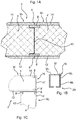
- FIG. 1A a part of a building construction system 2 of the present invention is illustrated in Fig. 1A .
- Fig. 1A is a schematic, cross-sectional top view of a portion of a building construction system 2 according to the invention.
- the building construction system 2 comprises a first module M 1 and a second, abutting module M 2 .
- the first module M 1 comprises a centrally arranged insulation member 4 sandwiched between a first cover plate 12 and a second cover plate 14.
- the second module M 2 comprises a centrally arranged insulation member 4' sandwiched between a first cover plate 12' and a second cover plate 14'.
- the insulation members 4, 4' are made in PUR or PIR.
- a reinforcement connection structure 10 (preferably made in a metal, e.g. steel) is provided between the adjacent insulation members 4, 4'.
- the reinforcement connection structure 10 is C-shaped and comprises a central portion extending between the first cover plates 12, 12' and the second cover plates 14, 14'.
- the joints 6, 6' between the adjacent first cover plates 12, 12' and the adjacent second cover plates 14, 14' are glued together.
- a connector 8 covers the back of the joint between the cover plates 14, 14, and another connector 8' covers the back of the joint between the other cover plates 12, 12.
- the distal and proximal portions of the reinforcement connection structure 10 abut the connectors 8, 8'.
- the connector 8 closest to the outside side of the modules M 1 , M 2 is preferably made in a cement-bonded particle board.
- the connector 8' closest to the inside side of the modules M 1 , M 2 is preferably made in a gypsum fiberboard.
- cover plates 14, 14' intended to be arranged closest to the outside side of the modules M 1 , M 2 are preferably made in cement-bonded particle board, whereas the cover plates 12, 12' intended to be arranged closest to the inside side of the modules M 1 , M 2 are preferably made in a gypsum fiberboard.
- Other suitable plate materials can be used.
- the modules M 1 , M 2 can be made through a manufacturing process in which the cover plates 12, 12', 14, 14', the corresponding connectors 8, 8' and the reinforcement connection structure 10 are glued together.
- the space between said structures is filled with an expanded foam such as PUR or PIR or a combination thereof.
- Fig. 1B illustrates a schematic, top view of a portion of a building 20 made by a building construction system according to the invention.
- the building 20 comprises a plurality of modules M 1 , M 2 , M 3 , M 4 attached to their neighbouring module.
- Fig. 1C illustrates a schematic, close-up view of the corner structure 16 of the building shown in Fig. 1B .
- the corner portion comprises a first module M 1 attached to a second module M 2 extending perpendicular to the first module M 1 .
- the first module M 1 comprises a first cover plate 12 and a second, opposing cover plate 14 extending parallel to each other.
- the first cover plate 12 is arranged at the indoor side and may be made of a gypsum fiberboard.
- the second cover plate 14 is arranged at the outdoor side and may be made of a cement-bonded particle board.
- the end portion of the first module M 1 comprises a cover plate 14", preferably made in a cement-bonded particle board.
- An insulation member 4 made in PUR or PIR is provided in the space defined by the cover plates 12, 14, 14".
- the plate-formed connecters 8, 8' are glued to the adjacent cover plates 12, 14, 14".
- the second module M 2 comprises a first cover plate 12' and a second, opposing cover plate 14' extending parallel to each other.
- the first cover plate 12', arranged at the indoor side, may be made of a gypsum fiberboard, whereas the second cover plate 14', arranged at the outdoor side, may be made of a cement-bonded particle board.
- An insulation member 4' made in PUR or PIR is provided in the space defined by the cover plates 12', 14'.
- a C-shaped reinforcement connection structure 10 is extending between a first, plate-formed connecter 8 and a second, plate-formed connector 8'.
- the plate-formed connecters 8, 8' are glued to the adjacent cover plates 12', 14'.
- the contact surface between the first module M 1 and the second module M 2 is glued.
- the first module M 1 and the second module M 2 are provided with matching mechanical attachment structures in order to maintain the first module M 1 and the second module M 2 positioned during the gluing process.
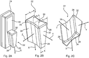
- Fig. 2A illustrates a schematic, perspective, top view of a wedge 22 according to the invention arranged adjacent to a construction element 24.
- the wedge 22 is arranged next to the construction element 24 provided with a recess 40, through which the wedge 22 can be inserted to attach the wedge 22 to the construction element 24.
- the wedge 22 comprises a top portion 30 extending perpendicular to the longitudinal axis X of the wedge 22.
- the wedge 22 moreover comprises a tapered front portion 32 extending parallel to the longitudinal axis X and being tapered in the direction of the longitudinal axis X.
- the wedge 22 further comprises side portions 38 having an arced profile.
- Fig. 2B illustrates a schematic, perspective, top view of the wedge 22 shown in Fig. 2A .
- the wedge 22 comprises a top portion 30 having a larger width W 3 at the end areas of the top portion 30 than the width W 2 at the central area of the top portion 30.
- the top portion 30 is encased by an arced edge structure 28.
- the top portion 30 extends perpendicular to the longitudinal axis X of the wedge 22.
- the wedge 22 has a tapered front portion 32 extending parallel to the longitudinal axis X from an arced edge structure 28 to the opposite narrow end having a width W 1 that is smaller than the width W 2 , W 3 indicated on the top portion 30.
- the front portion 32 extends perpendicular to the lateral axis Y of the wedge 22 and tapers in the direction of the longitudinal axis X.
- the wedge 22 comprises side portions 38 having an arced profile that basically extends perpendicular to the normal axis Z of the wedge 22.
- Fig. 2C illustrates another schematic, perspective, top view of the wedge 22 shown in Fig. 2A .
- the wedge 22 comprises a bottom portion 34 extending perpendicular to the longitudinal axis X of the wedge.
- the bottom portion 34 has a larger width at the end areas than at the central area.
- the corner regions of the wedge 22 are shaped as arced edge structures 28.
- the wedge 22 comprises a side portion 36 having an arced profile that basically extends perpendicular to the normal axis Z of the wedge 22.
- the wedge 22 comprises a tapered, plate-shaped front portion 32 extending perpendicular to the lateral axis Y of the wedge 22.
- the wedge 22 is configured to attach two elements to each other by arranging the wedge 22 in receiving structures of said elements (see Fig. 3A, Fig. 3B and Fig. 3C ).
- Fig. 3A illustrates a schematic, perspective, top view of a wall made by a construction system 2 according to the invention.
- the wall comprises three plate-shaped modules M 1 , M 2 , M 3 extending in extension of each other.
- the first module M 1 comprises a first cover plate 12.
- the second module M 2 comprises a second cover plate 12', whereas the third module M 3 comprises a third cover plate 12".
- the first cover plate 12 and the second cover plate 12' are provided with three receiving portions 46 comprising two recesses extending in extension of each other.
- the receiving portions 46 are configured to receive corresponding wedges 22 and locking blocks 44.
- a first joint 6 is provided between the first cover plate 12 and the second cover plate 12', and a second joint 6' is provided between the second cover plate 12' and the third cover plate 12".
- Fig. 3B illustrates a close-up view of the upper right corner portion of the wall in Fig. 3A .
- the third cover plate 12" of the wall is provided with a receiving portion 46.
- the wedge 22 is formed to be inserted into the upper recess 40 (indicated with the three parallel arrows) and hereafter moved downwards to be receivingly attached to a lower recess 42 as indicated with the large arrow.
- Fig. 3C illustrates a close-up view of the upper right corner portion of the wall shown in Fig. 3A and in Fig. 3B in a configuration, in which the wedge 22 has been moved downwards to be receivingly attached to a lower recess 42.
- a locking block 44 is being inserted into the upper recess 40 (indicated with the three parallel arrows).
- the locking block 44 will prevent the wedge 22 from being displaced upwardly. Accordingly, the wedge 22 is restricted from being removed from the lower recess 42 as long as the locking block 44 is positioned in the upper recess 40.
- Fig. 4A illustrates a schematic, front view of a wedge 22 according to the invention.
- Fig. 4B illustrates a schematic, side view of the wedge 22 shown in Fig. 4A.
- Fig. 4C illustrates a schematic, top view of the wedge 22 shown in Fig. 4A , whereas Fig. 4D illustrates a schematic, perspective, top view of the wedge 22 shown in Fig. 4A .
- the wedge 22 can be used to attach adjacent walls or other elements (e.g. attachment of a gutter to an outside structure of a building).
- the wedge 22 comprises a front portion 32 shaped as an isosceles trapezium, wherein the corner portions are rounded off.
- the front portion 32 has its largest width W 3 in the first end and the smallest width W 1 in the opposite end.
- the front portion 32 extends along the longitudinal axis X and the normal axis Z of the wedge 22.
- the wedge 22 comprises a side portion 38 having an arced profile.
- the projection of the side portion 38 shown in Fig. 4B is basically rectangular (however with rounded off corners).
- the wedge 22 comprises a top portion 30 extending basically along the lateral axis Y and the normal axis Z of the wedge 22.
- the top portion 30 has its largest width W 3 near the end areas and the smallest width W 1 in the central portion of the top portion 30.
- the wedge 22 is symmetric with respect to the plane spanned by the longitudinal axis and the normal axis Z.
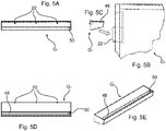
- Fig. 5A illustrates a schematic, rear view of a gutter G 1 according to the invention.
- the gutter G 1 comprises an outlet 50, from which water can be drained through a rainwater pipe (not shown).
- the gutter G 1 is provided with a plurality of wedges 22, evenly distributed along the back of the gutter G 1 .
- the wedges 22 are shaped and configured to be attached to receiving structures arranged on a building structure (e.g. the outside portion of a wall).
- Fig. 5C illustrates a schematic side view of the gutter G 1 shown in Fig. 5A .
- the gutter G 1 comprises a slit 48 extending along the longitudinal axis of the gutter G 1 .
- Fig. 5B illustrates a close-up view of the gutter G 1 shown in Fig. 5C .
- a wedge 22 is attached to and protrudes from the rear side of the gutter G 1 .
- the wedge 22 is configured to be used to attach the gutter G 1 to an upright wall of a building.
- Fig. 5D illustrates a schematic top view of the gutter G 1 shown in Fig. 5A
- Fig. 5E illustrates a schematic, perspective top view of the gutter G 1 shown in Fig. 5A
- Three wedges 22 are attached to and protrudes from the rear side of the gutter G 1 .
- a slit 48 extends along the longitudinal axis of the gutter G 1 , and an outlet 50 is arranged at the end portion of the gutter G 1 .
- Fig. 6A illustrates a front view of the long side of a building made by a building construction system according to the invention
- Fig. 6B illustrates a side view of the short side of the building shown in Fig. 6A
- the long side of the building comprises a plurality of modules M 1 , M 2 , M 3 , M 4 , M 5 , M 6 , M 8 , each attached to the adjacent module.
- Three gutters G 1 , G 2 , G 3 are attached to the upper portion of the long side of the building.
- Additional gutters G 4 , G 5 are arranged to the short sides of the building.
- the short side of the building comprises three modules M 9 , M 10 , M 11 , each attached to the adjacent module.
- a gutter G 4 is attached to the upper portion of the short side of the building.
- Fig. 7A illustrates a schematic, perspective top view of a wall made of a building construction system according to the invention.
- the wall comprises eight modules M 1 , M 2 , M 3 , M 4 , M 5 , M 6 , M 7 , M 8 arranged aligned in relation to the same longitudinal axis.
- An opening 60 is provided in the first module M 1 , the fifth module M 5 and the eighth module M 8 .
- the openings 60 are configured to receive a corresponding connection member as shown in Fig. 7B .
- a roof may be attached to the wall by means of connection members attached to the openings 60.
- the second module M 2 , the fifth module M 5 and the seventh module M 7 are provided with receiving portions 46 for attachment of wedges as the one shown in Fig. 2B and Fig. 4D .
- receiving portions 46 for attachment of wedges as the one shown in Fig. 2B and Fig. 4D .
- partitions vertically extending walls
- the end portion 62 of the eighth module M 8 is provided with three receiving portions 46.
- the eighth module M 8 can be attached to a wall to form a corner portion.
- Fig. 7B illustrates a close-up view of the top portion 58 of the first module M 1 of the wall shown in Fig. 7A . It can be seen that a connection member 52 has been inserted into the opening in the top portion 58 of the first module M 1 .
- Fig. 7C illustrates the connection member 52 shown in Fig. 7B .
- the connection member 52 comprises an upper, tubular insertion structure 54, a lower, tubular insertion structure 54' and an intermediate structure formed as a flat ring 56 provided there between.
- the openings 60 shown in Fig. 7A and in Fig. 7B are wide enough to receive the lower insertion structure 54', whereas the intermediate structure 56 is wide enough to prevent the connection member 52 from being moved further downwards once the intermediate structure 56 is pressed against the top portion. Accordingly, the connection members 52 can easily be detachably attached to the openings 60.
- Fig. 8A illustrates a perspective, top view of a module of a building construction system according to the invention before the insulation member has been provided into the space between the first cover plates 12, 12' and the second cover plates 14, 14'.
- Fig. 8B illustrates a cross-sectional view of the module shown in Fig. 8A .
- a C-shaped reinforcement connection structure 10 extends between a first connector 8 (supporting the joint 6 between the second cover plates 14, 14') and a second connector 8' (supporting the joint 6' between the first cover plates 12, 12').
- Fig. 8C illustrates a perspective, top view of another module of a building construction system according to the invention before the insulation member has been provided into the space between the first cover plates 12, 12' and the second cover plates 14, 14'.
- Fig. 8D illustrates a cross-sectional view of the module shown in Fig. 8C .
- a basically C-shaped reinforcement connection structure 10 extends between a first connector 8 (supporting the joint 6 between the second cover plates 14, 14') and a second connector 8' (supporting the joint 6' between the first cover plates 12, 12').
- the reinforcement connection structure 10 comprises a corrugated central portion.
- the mechanical stiffness of the reinforcement connection structure 10 can be increased.
- Fig. 8E illustrates a perspective, top view of a further module of a building construction system according to the invention before the insulation member has been provided into the space between the first cover plates 12, 12' and the second cover plates 14, 14'.
- Fig. 8F illustrates a cross-sectional view of the module shown in Fig. 8E .
- An I-shaped reinforcement connection structure 10 extends between a first connector 8 (supporting the joint 6 between the second cover plates 14, 14') and a second connector 8' (supporting the joint 6' between the first cover plates 12, 12').
- Fig. 8G illustrates a perspective, top view of a further module of a building construction system according to the invention before the insulation member has been provided into the space between the first cover plates 12, 12' and the second cover plates 14, 14'.
- Fig. 8H illustrates a cross-sectional view of the module shown in Fig. 8G .
- An I-shaped reinforcement connection structure 10 extends between the joint 6 between the second cover plates 14, 14' and the joint 6' between the first cover plates 12, 12'.
Landscapes
- Engineering & Computer Science (AREA)
- Architecture (AREA)
- Civil Engineering (AREA)
- Structural Engineering (AREA)
- Physics & Mathematics (AREA)
- Electromagnetism (AREA)
- Building Environments (AREA)
- Finishing Walls (AREA)
Applications Claiming Priority (3)
| Application Number | Priority Date | Filing Date | Title |
|---|---|---|---|
| DKPA201700407 | 2017-07-10 | ||
| EP18739812.8A EP3652388B1 (de) | 2017-07-10 | 2018-07-04 | System für die erstellung von gebäude |
| PCT/EP2018/068051 WO2019011744A1 (en) | 2017-07-10 | 2018-07-04 | BUILDING CONSTRUCTION SYSTEM |
Related Parent Applications (2)
| Application Number | Title | Priority Date | Filing Date |
|---|---|---|---|
| EP18739812.8A Division EP3652388B1 (de) | 2017-07-10 | 2018-07-04 | System für die erstellung von gebäude |
| EP18739812.8A Division-Into EP3652388B1 (de) | 2017-07-10 | 2018-07-04 | System für die erstellung von gebäude |
Publications (1)
| Publication Number | Publication Date |
|---|---|
| EP3936676A1 true EP3936676A1 (de) | 2022-01-12 |
Family
ID=59655809
Family Applications (2)
| Application Number | Title | Priority Date | Filing Date |
|---|---|---|---|
| EP21186136.4A Withdrawn EP3936676A1 (de) | 2017-07-10 | 2018-07-04 | Befestigungssystem |
| EP18739812.8A Active EP3652388B1 (de) | 2017-07-10 | 2018-07-04 | System für die erstellung von gebäude |
Family Applications After (1)
| Application Number | Title | Priority Date | Filing Date |
|---|---|---|---|
| EP18739812.8A Active EP3652388B1 (de) | 2017-07-10 | 2018-07-04 | System für die erstellung von gebäude |
Country Status (6)
| Country | Link |
|---|---|
| US (1) | US11746519B2 (de) |
| EP (2) | EP3936676A1 (de) |
| CN (1) | CN111133158B (de) |
| AU (1) | AU2018300705A1 (de) |
| DK (1) | DK3652388T3 (de) |
| WO (1) | WO2019011744A1 (de) |
Families Citing this family (4)
| Publication number | Priority date | Publication date | Assignee | Title |
|---|---|---|---|---|
| IT201800005662A1 (it) * | 2018-05-24 | 2019-11-24 | Metodo per la realizzazione di una parete, un solaio o simile formata da una pluralità di pannelli in legno fra loro intercollegati, parete attuata con questo metodo e un elemento di connessione per pannelli in legno in particolare pannelli in legno a strati incrociati incollati o giuntati meccanicamente per la realizzazione di una parete di questo tipo | |
| GB2590505B (en) * | 2019-12-20 | 2022-04-06 | Agr Living Ltd | Structural insulated panel (SIP) for a modular building |
| EP4127342A4 (de) * | 2020-03-27 | 2024-04-10 | Nexii Building Solutions Inc. | Systeme und verfahren zur konstruktion eines einstöckigen gebäudes |
| WO2024251336A1 (en) * | 2023-06-04 | 2024-12-12 | Smartpanels Aps | Method for manufacturing a building construction element and building construction element |
Citations (7)
| Publication number | Priority date | Publication date | Assignee | Title |
|---|---|---|---|---|
| US2347049A (en) * | 1942-08-19 | 1944-04-18 | Curtis Companies Inc | Structural joint |
| DE2422382A1 (de) * | 1974-05-09 | 1975-11-20 | Alfred Haener Gmbh Ing | Bausatz fuer eine verkleidung, eine trennwand, einen raumteiler oder dergleichen aus kunststoffteilen |
| GB2399539A (en) | 2003-03-18 | 2004-09-22 | Intelligent Engineering | Connecting structural sandwich plate members |
| EP2348161A2 (de) | 2010-01-26 | 2011-07-27 | Mjosutvikling As | Modulares System für den Bau von Haüser |
| US20150135634A1 (en) | 2013-11-15 | 2015-05-21 | Tor Hoie | Composite Building Components Building System |
| US20150354612A1 (en) * | 2014-05-23 | 2015-12-10 | Jon Russell Koch | Connector System for Rapid Assembly and Disassembly of Panels and Other Members |
| WO2016071747A2 (fr) | 2014-11-06 | 2016-05-12 | Eccologis | Nouvel élément de liaison isolant entre panneaux composites pour le bâtiment, nouveaux panneaux adaptés et procédé de construction de parois |
Family Cites Families (30)
| Publication number | Priority date | Publication date | Assignee | Title |
|---|---|---|---|---|
| US2647287A (en) * | 1950-07-14 | 1953-08-04 | U S Thermo Control Co | Locking mechanism |
| US2875478A (en) * | 1954-08-10 | 1959-03-03 | Frank V Andre | Building wall structure |
| US3313073A (en) * | 1962-09-24 | 1967-04-11 | Foam Products Corp | Joint assemblies for insulation panels |
| FR2034348A1 (en) * | 1969-03-19 | 1970-12-11 | Binot Christian | Tiling or parquet with sound proof flexible - support |
| US3783082A (en) * | 1971-03-31 | 1974-01-01 | E Almog | Panels and method of making same |
| ES250369Y (es) * | 1980-04-30 | 1981-01-16 | Juego de paneles para formacion de paredes atermanas | |
| US4443988A (en) * | 1981-10-02 | 1984-04-24 | Atlas Insulation Company, Inc. | Insulated building panel |
| US4712352A (en) * | 1985-12-04 | 1987-12-15 | Low R Glenn | Modular construction system |
| US5497589A (en) * | 1994-07-12 | 1996-03-12 | Porter; William H. | Structural insulated panels with metal edges |
| CA2156769C (en) * | 1994-08-24 | 1999-10-19 | William H. Porter | Structural insulated panel with metal edges |
| DE19608483A1 (de) * | 1996-03-05 | 1997-09-11 | Berreth Rainer Dipl Ing Fh | Vorgefertigte Leichtbauwand |
| DE29604911U1 (de) * | 1996-03-05 | 1996-06-13 | Berreth, Rainer, Dipl.-Ing. (FH), 73479 Ellwangen | Vorgefertigte Leichtbauwand |
| US5950389A (en) * | 1996-07-02 | 1999-09-14 | Porter; William H. | Splines for joining panels |
| US6041562A (en) * | 1998-02-17 | 2000-03-28 | Mar-Mex Canada Inc. | Composite wall construction and dwelling therefrom |
| US6119427A (en) * | 1998-04-29 | 2000-09-19 | Louisville Cooler Manufacturing Co. | Apparatus and method of modular panel construction |
| US6279287B1 (en) * | 1998-08-12 | 2001-08-28 | Shoshone Station Llc | Prefabricated building panel and method of manufacturing same |
| US6481172B1 (en) * | 2000-01-12 | 2002-11-19 | William H. Porter | Structural wall panels |
| US20050204697A1 (en) * | 2004-03-03 | 2005-09-22 | Rue Jerry R | Insulated structural building panel and assembly system |
| NL1028311C2 (nl) * | 2004-12-10 | 2006-06-13 | Beugt Houtz En Parketindustrie | Samenstel van twee met elkaar gekoppelde planken. |
| US8756889B2 (en) * | 2008-09-08 | 2014-06-24 | Dennis LeBlang | Metal stud building panel with foam block core |
| CN101775874B (zh) * | 2009-01-09 | 2012-10-17 | 亚士保温科技(上海)有限公司 | 一种提高牢固性的成型复合板及其制备方法 |
| CN201843253U (zh) * | 2010-10-27 | 2011-05-25 | 河南天丰节能板材科技股份有限公司 | 一种加强型复合板 |
| US8272182B1 (en) * | 2011-03-21 | 2012-09-25 | Conservation Technology International, Inc. | Frame unit and method |
| WO2014043231A1 (en) * | 2012-09-11 | 2014-03-20 | David Gibson | Construction panel system and assembly method thereof |
| US10024057B2 (en) * | 2012-09-11 | 2018-07-17 | A. David Gibson | Construction panel system and methods of assembly thereof |
| US9057199B2 (en) * | 2013-03-06 | 2015-06-16 | Jerry GILLMAN | Structural insulated building panel with a moisture barrier seal |
| US8844243B1 (en) * | 2013-03-06 | 2014-09-30 | Jerry GILLMAN | Method of connecting structural insulated building panels through connecting splines |
| US9890531B2 (en) * | 2015-04-08 | 2018-02-13 | Barnet L. Liberman | Modular building system with adhesive-joined spline connections between wall sections |
| DE202015005886U1 (de) * | 2015-08-20 | 2015-10-05 | Markus Rensburg | Montagebeschlag zur gegenseitigen Positionierung von Fertigbauelementen |
| US11174633B2 (en) * | 2020-03-09 | 2021-11-16 | Trango-Sys Ltd. | Modular construction system and method of use thereof |
-
2018
- 2018-07-04 EP EP21186136.4A patent/EP3936676A1/de not_active Withdrawn
- 2018-07-04 CN CN201880057337.2A patent/CN111133158B/zh not_active Expired - Fee Related
- 2018-07-04 WO PCT/EP2018/068051 patent/WO2019011744A1/en not_active Ceased
- 2018-07-04 DK DK18739812.8T patent/DK3652388T3/da active
- 2018-07-04 EP EP18739812.8A patent/EP3652388B1/de active Active
- 2018-07-04 AU AU2018300705A patent/AU2018300705A1/en not_active Abandoned
-
2020
- 2020-01-10 US US16/739,751 patent/US11746519B2/en active Active
Patent Citations (7)
| Publication number | Priority date | Publication date | Assignee | Title |
|---|---|---|---|---|
| US2347049A (en) * | 1942-08-19 | 1944-04-18 | Curtis Companies Inc | Structural joint |
| DE2422382A1 (de) * | 1974-05-09 | 1975-11-20 | Alfred Haener Gmbh Ing | Bausatz fuer eine verkleidung, eine trennwand, einen raumteiler oder dergleichen aus kunststoffteilen |
| GB2399539A (en) | 2003-03-18 | 2004-09-22 | Intelligent Engineering | Connecting structural sandwich plate members |
| EP2348161A2 (de) | 2010-01-26 | 2011-07-27 | Mjosutvikling As | Modulares System für den Bau von Haüser |
| US20150135634A1 (en) | 2013-11-15 | 2015-05-21 | Tor Hoie | Composite Building Components Building System |
| US20150354612A1 (en) * | 2014-05-23 | 2015-12-10 | Jon Russell Koch | Connector System for Rapid Assembly and Disassembly of Panels and Other Members |
| WO2016071747A2 (fr) | 2014-11-06 | 2016-05-12 | Eccologis | Nouvel élément de liaison isolant entre panneaux composites pour le bâtiment, nouveaux panneaux adaptés et procédé de construction de parois |
Also Published As
| Publication number | Publication date |
|---|---|
| AU2018300705A1 (en) | 2020-01-16 |
| EP3652388A1 (de) | 2020-05-20 |
| CN111133158A (zh) | 2020-05-08 |
| CN111133158B (zh) | 2022-03-18 |
| US11746519B2 (en) | 2023-09-05 |
| US20200149265A1 (en) | 2020-05-14 |
| WO2019011744A1 (en) | 2019-01-17 |
| EP3652388B1 (de) | 2021-08-25 |
| DK3652388T3 (da) | 2021-11-22 |
Similar Documents
| Publication | Publication Date | Title |
|---|---|---|
| US11746519B2 (en) | Building construction system | |
| CA2597079C (en) | Improved structural insulated panel and panel joint | |
| CA1279970C (en) | Thermally insulating structural panel | |
| US4641468A (en) | Panel structure and building structure made therefrom | |
| US6226942B1 (en) | Building construction panels and method thereof | |
| US6698157B1 (en) | Structural insulated panel building system | |
| CA2430472C (en) | Cellular-core structural panel, and building structure incorporating same | |
| US20120011792A1 (en) | High strength light-framed wall structure | |
| US20120247038A1 (en) | Construction system using interlocking panels | |
| EP3791031B1 (de) | Schaumstoffwandstrukturen mit hoher scherfestigkeit und verfahren zu ihrer herstellung | |
| US10316515B2 (en) | Structural insulated sheathing | |
| EP0006756B1 (de) | Tragende, zusammengesetzte Platte | |
| WO2013043735A1 (en) | System and method of manufacture for building panels | |
| US20160237683A1 (en) | Building Panels - Systems Components & Methods | |
| US4193244A (en) | Building block and module system for house building | |
| KR20170028934A (ko) | 벽 구조물용 건축 블럭 | |
| CN102472042A (zh) | 用于一隔离建筑系统的具有拐角轮廓的建筑组件 | |
| RU2767836C1 (ru) | Строительная система и способ возведения здания | |
| CN214785290U (zh) | 一种易于组装的用于装配式建筑的预制木板材 | |
| CA3028289A1 (en) | Composite structural beam | |
| JP2569212Y2 (ja) | 構造用多機能パネルの接合構造 | |
| AU2002217928B2 (en) | Cellular-core structural panel, and building structure incorporating same | |
| JPH0932180A (ja) | 小屋パネル及び妻パネル並びにそれらの施工方法 | |
| NZ548660A (en) | Building structure incorporating cellular-core roof panels spanning from ridge to walls and connected to tension bearing members | |
| AU2002217928A1 (en) | Cellular-core structural panel, and building structure incorporating same |
Legal Events
| Date | Code | Title | Description |
|---|---|---|---|
| PUAI | Public reference made under article 153(3) epc to a published international application that has entered the european phase |
Free format text: ORIGINAL CODE: 0009012 |
|
| STAA | Information on the status of an ep patent application or granted ep patent |
Free format text: STATUS: THE APPLICATION HAS BEEN PUBLISHED |
|
| AC | Divisional application: reference to earlier application |
Ref document number: 3652388 Country of ref document: EP Kind code of ref document: P |
|
| AK | Designated contracting states |
Kind code of ref document: A1 Designated state(s): AL AT BE BG CH CY CZ DE DK EE ES FI FR GB GR HR HU IE IS IT LI LT LU LV MC MK MT NL NO PL PT RO RS SE SI SK SM TR |
|
| B565 | Issuance of search results under rule 164(2) epc |
Effective date: 20211109 |
|
| RAP1 | Party data changed (applicant data changed or rights of an application transferred) |
Owner name: MOELLER S.R.O. |
|
| STAA | Information on the status of an ep patent application or granted ep patent |
Free format text: STATUS: THE APPLICATION IS DEEMED TO BE WITHDRAWN |
|
| 18D | Application deemed to be withdrawn |
Effective date: 20220713 |