EP3936700A1 - Élément de liaison et dispositif de liaison anti-décalage thermique - Google Patents
Élément de liaison et dispositif de liaison anti-décalage thermique Download PDFInfo
- Publication number
- EP3936700A1 EP3936700A1 EP20924980.4A EP20924980A EP3936700A1 EP 3936700 A1 EP3936700 A1 EP 3936700A1 EP 20924980 A EP20924980 A EP 20924980A EP 3936700 A1 EP3936700 A1 EP 3936700A1
- Authority
- EP
- European Patent Office
- Prior art keywords
- connector
- central shaft
- convex annular
- annular rib
- plates
- Prior art date
- Legal status (The legal status is an assumption and is not a legal conclusion. Google has not performed a legal analysis and makes no representation as to the accuracy of the status listed.)
- Granted
Links
Images

Classifications
-
- F—MECHANICAL ENGINEERING; LIGHTING; HEATING; WEAPONS; BLASTING
- F16—ENGINEERING ELEMENTS AND UNITS; GENERAL MEASURES FOR PRODUCING AND MAINTAINING EFFECTIVE FUNCTIONING OF MACHINES OR INSTALLATIONS; THERMAL INSULATION IN GENERAL
- F16B—DEVICES FOR FASTENING OR SECURING CONSTRUCTIONAL ELEMENTS OR MACHINE PARTS TOGETHER, e.g. NAILS, BOLTS, CIRCLIPS, CLAMPS, CLIPS OR WEDGES; JOINTS OR JOINTING
- F16B19/00—Bolts without screw-thread; Pins, including deformable elements; Rivets
- F16B19/02—Bolts or sleeves for positioning of machine parts, e.g. notched taper pins, fitting pins, sleeves, eccentric positioning rings
-
- F—MECHANICAL ENGINEERING; LIGHTING; HEATING; WEAPONS; BLASTING
- F01—MACHINES OR ENGINES IN GENERAL; ENGINE PLANTS IN GENERAL; STEAM ENGINES
- F01D—NON-POSITIVE DISPLACEMENT MACHINES OR ENGINES, e.g. STEAM TURBINES
- F01D25/00—Component parts, details, or accessories, not provided for in, or of interest apart from, other groups
- F01D25/24—Casings; Casing parts, e.g. diaphragms, casing fastenings
- F01D25/246—Fastening of diaphragms or stator-rings
-
- F—MECHANICAL ENGINEERING; LIGHTING; HEATING; WEAPONS; BLASTING
- F01—MACHINES OR ENGINES IN GENERAL; ENGINE PLANTS IN GENERAL; STEAM ENGINES
- F01D—NON-POSITIVE DISPLACEMENT MACHINES OR ENGINES, e.g. STEAM TURBINES
- F01D11/00—Preventing or minimising internal leakage of working-fluid, e.g. between stages
- F01D11/08—Preventing or minimising internal leakage of working-fluid, e.g. between stages for sealing space between rotor blade tips and stator
-
- F—MECHANICAL ENGINEERING; LIGHTING; HEATING; WEAPONS; BLASTING
- F01—MACHINES OR ENGINES IN GENERAL; ENGINE PLANTS IN GENERAL; STEAM ENGINES
- F01D—NON-POSITIVE DISPLACEMENT MACHINES OR ENGINES, e.g. STEAM TURBINES
- F01D25/00—Component parts, details, or accessories, not provided for in, or of interest apart from, other groups
- F01D25/28—Supporting or mounting arrangements, e.g. for turbine casing
-
- F—MECHANICAL ENGINEERING; LIGHTING; HEATING; WEAPONS; BLASTING
- F05—INDEXING SCHEMES RELATING TO ENGINES OR PUMPS IN VARIOUS SUBCLASSES OF CLASSES F01-F04
- F05D—INDEXING SCHEME FOR ASPECTS RELATING TO NON-POSITIVE-DISPLACEMENT MACHINES OR ENGINES, GAS-TURBINES OR JET-PROPULSION PLANTS
- F05D2230/00—Manufacture
- F05D2230/60—Assembly methods
- F05D2230/64—Assembly methods using positioning or alignment devices for aligning or centring, e.g. pins
- F05D2230/642—Assembly methods using positioning or alignment devices for aligning or centring, e.g. pins using maintaining alignment while permitting differential dilatation
-
- F—MECHANICAL ENGINEERING; LIGHTING; HEATING; WEAPONS; BLASTING
- F05—INDEXING SCHEMES RELATING TO ENGINES OR PUMPS IN VARIOUS SUBCLASSES OF CLASSES F01-F04
- F05D—INDEXING SCHEME FOR ASPECTS RELATING TO NON-POSITIVE-DISPLACEMENT MACHINES OR ENGINES, GAS-TURBINES OR JET-PROPULSION PLANTS
- F05D2240/00—Components
- F05D2240/10—Stators
- F05D2240/11—Shroud seal segments
-
- F—MECHANICAL ENGINEERING; LIGHTING; HEATING; WEAPONS; BLASTING
- F05—INDEXING SCHEMES RELATING TO ENGINES OR PUMPS IN VARIOUS SUBCLASSES OF CLASSES F01-F04
- F05D—INDEXING SCHEME FOR ASPECTS RELATING TO NON-POSITIVE-DISPLACEMENT MACHINES OR ENGINES, GAS-TURBINES OR JET-PROPULSION PLANTS
- F05D2240/00—Components
- F05D2240/10—Stators
- F05D2240/14—Casings or housings protecting or supporting assemblies within
-
- F—MECHANICAL ENGINEERING; LIGHTING; HEATING; WEAPONS; BLASTING
- F05—INDEXING SCHEMES RELATING TO ENGINES OR PUMPS IN VARIOUS SUBCLASSES OF CLASSES F01-F04
- F05D—INDEXING SCHEME FOR ASPECTS RELATING TO NON-POSITIVE-DISPLACEMENT MACHINES OR ENGINES, GAS-TURBINES OR JET-PROPULSION PLANTS
- F05D2250/00—Geometry
- F05D2250/10—Two-dimensional
- F05D2250/15—Two-dimensional spiral
-
- F—MECHANICAL ENGINEERING; LIGHTING; HEATING; WEAPONS; BLASTING
- F05—INDEXING SCHEMES RELATING TO ENGINES OR PUMPS IN VARIOUS SUBCLASSES OF CLASSES F01-F04
- F05D—INDEXING SCHEME FOR ASPECTS RELATING TO NON-POSITIVE-DISPLACEMENT MACHINES OR ENGINES, GAS-TURBINES OR JET-PROPULSION PLANTS
- F05D2250/00—Geometry
- F05D2250/20—Three-dimensional
- F05D2250/23—Three-dimensional prismatic
- F05D2250/231—Three-dimensional prismatic cylindrical
-
- F—MECHANICAL ENGINEERING; LIGHTING; HEATING; WEAPONS; BLASTING
- F05—INDEXING SCHEMES RELATING TO ENGINES OR PUMPS IN VARIOUS SUBCLASSES OF CLASSES F01-F04
- F05D—INDEXING SCHEME FOR ASPECTS RELATING TO NON-POSITIVE-DISPLACEMENT MACHINES OR ENGINES, GAS-TURBINES OR JET-PROPULSION PLANTS
- F05D2250/00—Geometry
- F05D2250/20—Three-dimensional
- F05D2250/27—Three-dimensional hyperboloid
-
- F—MECHANICAL ENGINEERING; LIGHTING; HEATING; WEAPONS; BLASTING
- F05—INDEXING SCHEMES RELATING TO ENGINES OR PUMPS IN VARIOUS SUBCLASSES OF CLASSES F01-F04
- F05D—INDEXING SCHEME FOR ASPECTS RELATING TO NON-POSITIVE-DISPLACEMENT MACHINES OR ENGINES, GAS-TURBINES OR JET-PROPULSION PLANTS
- F05D2250/00—Geometry
- F05D2250/30—Arrangement of components
- F05D2250/31—Arrangement of components according to the direction of their main axis or their axis of rotation
- F05D2250/314—Arrangement of components according to the direction of their main axis or their axis of rotation the axes being inclined in relation to each other
-
- F—MECHANICAL ENGINEERING; LIGHTING; HEATING; WEAPONS; BLASTING
- F05—INDEXING SCHEMES RELATING TO ENGINES OR PUMPS IN VARIOUS SUBCLASSES OF CLASSES F01-F04
- F05D—INDEXING SCHEME FOR ASPECTS RELATING TO NON-POSITIVE-DISPLACEMENT MACHINES OR ENGINES, GAS-TURBINES OR JET-PROPULSION PLANTS
- F05D2250/00—Geometry
- F05D2250/70—Shape
- F05D2250/71—Shape curved
- F05D2250/711—Shape curved convex
-
- F—MECHANICAL ENGINEERING; LIGHTING; HEATING; WEAPONS; BLASTING
- F05—INDEXING SCHEMES RELATING TO ENGINES OR PUMPS IN VARIOUS SUBCLASSES OF CLASSES F01-F04
- F05D—INDEXING SCHEME FOR ASPECTS RELATING TO NON-POSITIVE-DISPLACEMENT MACHINES OR ENGINES, GAS-TURBINES OR JET-PROPULSION PLANTS
- F05D2260/00—Function
- F05D2260/30—Retaining components in desired mutual position
- F05D2260/36—Retaining components in desired mutual position by a form fit connection, e.g. by interlocking
-
- F—MECHANICAL ENGINEERING; LIGHTING; HEATING; WEAPONS; BLASTING
- F05—INDEXING SCHEMES RELATING TO ENGINES OR PUMPS IN VARIOUS SUBCLASSES OF CLASSES F01-F04
- F05D—INDEXING SCHEME FOR ASPECTS RELATING TO NON-POSITIVE-DISPLACEMENT MACHINES OR ENGINES, GAS-TURBINES OR JET-PROPULSION PLANTS
- F05D2260/00—Function
- F05D2260/30—Retaining components in desired mutual position
- F05D2260/38—Retaining components in desired mutual position by a spring, i.e. spring loaded or biased towards a certain position
-
- F—MECHANICAL ENGINEERING; LIGHTING; HEATING; WEAPONS; BLASTING
- F05—INDEXING SCHEMES RELATING TO ENGINES OR PUMPS IN VARIOUS SUBCLASSES OF CLASSES F01-F04
- F05D—INDEXING SCHEME FOR ASPECTS RELATING TO NON-POSITIVE-DISPLACEMENT MACHINES OR ENGINES, GAS-TURBINES OR JET-PROPULSION PLANTS
- F05D2300/00—Materials; Properties thereof
- F05D2300/60—Properties or characteristics given to material by treatment or manufacturing
- F05D2300/603—Composites; e.g. fibre-reinforced
- F05D2300/6033—Ceramic matrix composites [CMC]
-
- F—MECHANICAL ENGINEERING; LIGHTING; HEATING; WEAPONS; BLASTING
- F16—ENGINEERING ELEMENTS AND UNITS; GENERAL MEASURES FOR PRODUCING AND MAINTAINING EFFECTIVE FUNCTIONING OF MACHINES OR INSTALLATIONS; THERMAL INSULATION IN GENERAL
- F16B—DEVICES FOR FASTENING OR SECURING CONSTRUCTIONAL ELEMENTS OR MACHINE PARTS TOGETHER, e.g. NAILS, BOLTS, CIRCLIPS, CLAMPS, CLIPS OR WEDGES; JOINTS OR JOINTING
- F16B2200/00—Constructional details of connections not covered for in other groups of this subclass
- F16B2200/50—Flanged connections
- F16B2200/506—Flanged connections bolted or riveted
-
- F—MECHANICAL ENGINEERING; LIGHTING; HEATING; WEAPONS; BLASTING
- F16—ENGINEERING ELEMENTS AND UNITS; GENERAL MEASURES FOR PRODUCING AND MAINTAINING EFFECTIVE FUNCTIONING OF MACHINES OR INSTALLATIONS; THERMAL INSULATION IN GENERAL
- F16B—DEVICES FOR FASTENING OR SECURING CONSTRUCTIONAL ELEMENTS OR MACHINE PARTS TOGETHER, e.g. NAILS, BOLTS, CIRCLIPS, CLAMPS, CLIPS OR WEDGES; JOINTS OR JOINTING
- F16B35/00—Screw-bolts; Stay-bolts; Screw-threaded studs; Screws; Set screws
- F16B35/02—Screw-bolts; Stay-bolts; Screw-threaded studs; Screws; Set screws divided longitudinally
Definitions
- This disclosure relates to the field of turbine outer annular component of turbine aeroengine, in particular to a connector with a subtractive hollow section, and an anti thermal mismatch connecting device.
- turbine outer annular component bears high ambient temperature in service.
- turbine outer annular component is mainly made of superalloy materials.
- the strength and stiffness of superalloy materials will decrease significantly under high temperature environment, which will affect the upper limit of service temperature of the turbine outer annular component, and ultimately limit the improvement of overall performance of gas turbine engine.
- CMC ceramic matrix composites
- Using ceramic matrix composites (CMC) instead of superalloys to produce the turbine outer annular component of gas turbine engine can give full play to the characteristics of CMC, such as low density, excellent high temperature mechanical properties and good thermal stability, thereby improving the upper limit of service temperature of the turbine outer annular component, and reducing the amount of related cooling gas, which plays an important role in significantly improving the overall efficiency of gas turbine engine and reducing pollution emissions.
- thermal expansion coefficient of metal material is greater than that of ceramic matrix composite, the thermal expansion of a CMC turbine outer annular component in a temperature change process, is different from that of a metal pin and a metal intermediate casing component. The thermal deformation difference between them will cause a significant thermal deformation mismatch in the above-mentioned connecting and installing structure.
- the purpose of the disclosure is to provide a connector which can prevent the mismatch problem of thermal deformation between connected parts.
- Another purpose of the disclosure is to provide an anti thermal mismatch connecting device.
- the connector to achieve the purpose has a rod part.
- the rod part of the connector comprises a subtractive hollow section and a cylindrical section.
- the subtractive hollow section comprises a central shaft, a plurality of supporting rib plates, extending outwards from a peripheral surface of the central shaft and inclined radially relative to the central shaft, and a plurality of outer annular plates, arranged around the central shaft. A circumferential gap is provided between adjacent outer annular plates.
- the supporting rib plate is connected with the central shaft and the outer annular plate, and the central shaft is connected with the cylindrical section.
- the plurality of the supporting rib plates are arranged in a rotationally symmetric form along the central shaft.
- the central shaft and the cylindrical section are connected or welded by a threaded connection structure.
- outer surfaces of the plurality of the outer annular plates are located on a same cylindrical surface, and the cylindrical surface is located in an axial extension direction of an outer surface of the cylindrical section.
- the connecting device for the purpose of providing thermal mismatch protection, comprising the connector; a CMC turbine outer annular component, with an outer convex annular rib plate at an outer circumference; and a metal intermediate casing, with an inner convex annular rib plate at an inner circumference.
- the outer convex annular rib plate has a CMC connecting hole
- the inner convex annular rib plate has a metal connecting hole.
- a cylindrical section of the connector is matched with the metal connecting hole of the inner convex annular rib plate.
- the subtractive hollow section of the connector is inserted into the CMC connecting hole, and the plurality of the outer annular plates are matched with the CMC connecting hole in a close contact, to generate an installation preload on the supporting rib plate.
- the metal intermediate casing provides two limit rings.
- the CMC turbine outer annular component provides two outer convex annular rib plates.
- the two outer convex annular rib plates are located between the two limit rings, and outer edges of the two outer convex annular rib plates are respectively abutted on the adjacent limit ring.
- the metal intermediate casing provides three inner convex annular rib plates.
- the two outer convex annular rib plates and the three inner convex annular rib plates are staggered along an axial direction of an engine, to make any one of the two outer convex annular rib plates located between two inner convex annular rib plates.
- the metal intermediate casing provides a plurality of the inner convex annular rib plates.
- the metal connecting holes of the plurality of the inner convex annular rib plates, which are matched with one of the connector, are round holes, and rest of the metal connecting holes are runway shaped connecting holes.
- an outer surface of the subtractive hollow section on the connector has a small radial deformation stiffness and is prone to radial elastic deformation. This will allow the outer surface of the subtractive hollow section to expand and deform, under the restriction of the inner circumference surface of the CMC connecting holes, during a heating process, and there will be no great contact stress between the two. Therefore, the thermal deformation mismatch between the two can be alleviated, and the strength failure of the structure can be avoided.
- a group of round holes, as well as a plurality of groups of runway shaped connecting holes, are designed and processed on the metal intermediate casing.
- the round holes are used to fit closely with one connector to ensure the accurate installation and positioning of CMC turbine outer annular component.
- the runway shaped connecting holes allow the connector fit with them to slide along a specified direction, so as to solve the mismatch problem of thermal deformation, between the connector which is completely limited and fixed by the CMC connecting holes, and the metal connecting holes on the metal intermediate casing.
- the connector with the subtractive hollow section and the anti thermal mismatch connecting device By designing the connector with the subtractive hollow section and the anti thermal mismatch connecting device, an accurate installation and positioning between the CMC turbine outer annular component and the metal intermediate casing of the turbine engine is realized, and the vibration and collision can be avoided. Meanwhile, under the change of ambient temperature, the thermal deformation mismatch between the CMC turbine outer annular component, the metal intermediate casing and the connector is alleviated, the problem of structural strength failure or the functional failure due to structural relaxation is avoided. Meanwhile, the CMC turbine outer annular component is also ensured to have enough installation stiffness to meet the design needs. The simplicity of the connection and installation structure is beneficial to significantly reduce the technical and operational difficulties of the CMC turbine outer annular component in the aspects of production, subsequent processing and installation.
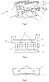
- FIG. 1 and Fig. 2 specifically show a CMC turbine outer annular component 1, a connector 2 and a metal intermediate casing 3.
- Fig. 1 and Fig. 2 also show CMC connecting holes 11, metal connecting holes 31, outer convex annular rib plates 12, inner convex annular rib plates 13, limit rings 32 and a cap part 23 of the connector 2.
- Fig. 1 and Fig. 2 only show a part of the CMC turbine outer annular component 1 and metal intermediate casing 3, cut along a radial direction of the turbine.
- the outer convex annular rib plates 12 and the inner convex annular rib plates 13 are both annular parts around the center of the turbine.
- the CMC turbine outer annular component 1 provides two outer convex annular rib plates 12, and the metal intermediate casing 3 provides three inner convex annular rib plates 13.
- the two outer convex annular rib plates 12 and the three inner convex annular rib plates 13 are staggered along an axial direction of the engine, so that any one of the two outer convex annular rib plates 12 is located between two of the inner convex annular rib plates 13.
- the connection configuration shown in Fig. 1 and Fig. 2 provides a plurality of connecting points connected by the connector 2 to provide a uniform and reliable connection.
- the metal intermediate casing 3 provides two limit rings 32, which can be continuous annular structures or a plurality of support points distributed along the metal intermediate casing 3.
- the two outer convex annular rib plates 12 are located between the two limit rings 32, and the outer edges of the two outer convex annular rib plates 12 respectively abut against an adjacent limit ring 32, thereby limiting the degree of freedom of the CMC turbine outer annular component 1 in the axial direction of the engine.
- the limit rings 32 can also be placed at other positions on the metal intermediate casing 3 in other geometric forms. It only needs to play an axial limiting and positioning role for the CMC turbine outer annular component 1.
- Fig. 3 shows a structural diagram of the CMC turbine outer annular component 1.
- the CMC connecting holes 11 on the outer convex annular rib plates 12 on the CMC turbine outer annular component 1 are all round holes.
- Fig. 4 shows a schematic diagram of the structure of the metal intermediate casing 3.
- the metal intermediate casing 3 provides a plurality of inner convex annular rib plates 13.
- the plurality of the inner convex annular rib plates 13 respectively provide metal connecting holes 31, which form a group and can be passed through by the metal connector 2. Therefore, a plurality of groups of the metal connecting holes 31 are distributed along the whole circumference of the metal intermediate casing 3.
- Fig. 1 to Fig. 4 only two groups of the metal connecting holes 31 are shown.
- one group of the metal connecting holes 31 are round holes 311, and the other groups of the metal connecting holes 31 are runway shaped connecting holes 312.
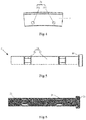
- Fig. 5 and Fig. 6 show a first embodiment of the connector 2, which has an integrated processing structure.
- the connector 2 comprises a rod part 24.
- the connector 2 also comprises a cap part 23, which is used to limit an axial degree of freedom of the connector 2.
- the axial degree of freedom of the connector 2 is not limited by the cap part, but is limited and fixed by a feature of screw fit nut, or a form of end butting with adjacent parts.
- the rod part 24 comprises a subtractive hollow section 21 and a cylindrical section 22.
- the cylindrical section 22 can be hollow or solid.
- the integrated processing structure is suitable to be processed and produced by a processing method such as precision casting or 3D printing.
- Fig. 7 and Fig. 8 show a second embodiment of the connector 2, which has a segmented processing structure.
- the subtractive hollow section 21 and the cylindrical section 22 are produced by separate processing, and the subtractive hollow section 21 can also be processed by a processing method such as wire cutting with high speed and low cost.
- the adjacent subtractive hollow section 21 and the cylindrical section 22 can be connected by a threaded connection structure shown in Fig. 8 , or by welding.
- the subtractive hollow section 21 comprises a central shaft 211, a plurality of supporting rib plates 212, a plurality of outer annular plates 213 and a plurality of circumferential gaps 214.
- the supporting rib plates 212 extends outwards from a peripheral surface of the central shaft 211 and is inclined radially to the central shaft 211, for example, extends in a spiral shape and is rotationally symmetrical along the central shaft 211.
- the outer annular plates 213 are arranged around the central shaft 211, with a circumferential gap 214 between adjacent outer annular plates 213.
- the supporting rib plates 212 are connected with the central shaft 211 and the outer annular plates 213, and the central shaft 211 and the cylindrical section 22 on the connector 2 are connected by a threaded connection structure or welded.
- the diameter of the peripheral surface of the central shaft 211, the extended shape, radial dimension and quantity of the supporting rib plates 212, the cross-sectional shape, surface diameter and quantity of the outer annular plates 213, and the shape, width and quantity of the circumferential gaps 214 can be changed according to the structural design, without maintaining a fixed corresponding relationship with the diameter of the subtractive hollow section 21.
- the dimension relationship to be ensured is that the surface of the outer annular plates 213 and the inner circumferential surface of the CMC connecting holes 11 should be closely attached and generate a certain contact force under a room temperature installation state.
- the numbers of the supporting rib plates 212, the outer annular plates 213 and the circumferential gaps 214 is the same.
- the CMC turbine outer annular component 1 and the metal intermediate casing 3 are assembled.
- the CMC turbine outer annular component 1 provides two outer convex annular rib plates 12, and the metal intermediate casing 3 provides three inner convex annular rib plates 13.
- the two outer convex annular rib plates 12 and the three inner convex annular rib plates 13 are staggered along the axial direction of the engine, so that any one of the two outer convex annular rib plates 12 is located between two of the inner convex annular rib plates 13.
- the metal intermediate casing 3 also provides two limit rings 32.
- Two outer convex annular rib plates 12 on CMC turbine outer annular component 1 are located between the two limit rings 32, and the outer edges of the two outer convex annular rib plates 12 respectively abut against an adjacent limit ring 32, thereby limiting the degree of freedom of the CMC turbine outer annular component 1 in the axial direction of the engine.
- the connectors 2 are alternately passed through the metal connecting holes 31 on the metal intermediate casing 3 and the CMC connecting holes 11 on the CMC turbine outer annular component 1, to install and fix the CMC turbine outer annular component 1 and the metal intermediate casing 3.
- the rod part 24 of the connector 2 comprises a subtractive hollow section 21 and a cylindrical section 22.
- the cylindrical section 22 is connected with the central shaft 211 of the subtractive hollow section 21 by threaded connection or welding.
- the outer surfaces of the subtractive hollow section 21 of the connector 2 are fitted with the CMC connecting holes 11 on the outer convex annular rib plate 12, so that the surfaces of the plurality of the outer annular plates 213, arranged around the central shaft 211 on the subtractive hollow section 21, are closely attached with the inner circumferential surfaces of the CMC connecting holes 11, and a certain contact force and an installation preload are generated, which can avoid the vibration and collision problems caused by a reserved assembly gap.
- a plurality of supporting rib plates 212, extending outwards from the peripheral surface of the central shaft and inclined radially relative to the central shaft, are arranged between the outer annular plates 213 and the central shaft 211, and a plurality of circumferential gaps 214 are provided between adjacent outer annular plates 213.
- the numbers of the supporting rib plates 212, the outer annular plates 213 and the circumferential gaps 214 are the same.
- the thermal expansion of the CMC turbine outer annular component 1 is different from that of the connector 2 and the metal intermediate casing 3, while the outer surface of the subtractive hollow section 21 on the connector 2 has smaller radial deformation stiffness when it contacts with the CMC connecting hole 11, and is prone to radial elastic deformation.
- This allows the expansion deformation of the outer surface of the subtractive hollow section 21, under the limit of the inner circumferential surfaces of the CMC connecting holes 11 during the heating process. Meanwhile, there will be no great contact stress between the two.
- the thermal deformation mismatch during the heating process, between the two, is alleviated, and the strength failure of the structure is avoided.
- the existence of the subtractive hollow section 21 will not significantly reduce the overall deformation stiffness of the connector, thereby ensuring the overall stiffness of the whole anti thermal mismatch connecting device to meet the design needs.
- the outer surface of the cylindrical section 22 of the connector 2 is closely matched with the metal connecting hole 31 on the inner convex annular rib plate 13.
- a kind of round hole 311 of the metal connecting hole 31 is closely matched with the cylindrical section 22 on a first connector 2, which is used to realize the accurate installation and positioning of the CMC outer annular component 1.
- Another kind of raceway shaped connecting hole 312 of the metal connecting hole 31 is closely matched with the cylindrical section 22 on a second connector 2.
- the raceway shaped connecting hole 312 allows the second connector 2 to slide in a specified direction, thereby alleviating the mismatch problem of thermal deformation between the connector 2, which is completely limited and fixed by the CMC connection hole 11, and the metal connecting hole 31 on the metal intermediate casing 3.
- the connector 2 with the subtractive hollow section 21 and the anti thermal mismatch connecting device, the mechanical connection and installation of the CMC turbine outer annular component 1 on a gas turbine engine are realized, and the mismatch problem of thermal deformation of connection structure among the CMC turbine outer annular component, the metal intermediate casing and the connectors, is alleviated, thereby avoiding the problems of structural strength failure or structural relaxation caused by high thermal mismatch stress, and the problems of vibration and collision caused by a reserved gap, which is of great value for the engineering application of the CMC turbine outer annular component.
Landscapes
- Engineering & Computer Science (AREA)
- General Engineering & Computer Science (AREA)
- Mechanical Engineering (AREA)
- Connection Of Plates (AREA)
- Turbine Rotor Nozzle Sealing (AREA)
- Standing Axle, Rod, Or Tube Structures Coupled By Welding, Adhesion, Or Deposition (AREA)
- Mutual Connection Of Rods And Tubes (AREA)
Applications Claiming Priority (2)
| Application Number | Priority Date | Filing Date | Title |
|---|---|---|---|
| CN202010392432.7A CN113638774B (zh) | 2020-05-11 | 2020-05-11 | 一种连接件及防热失配连接装置 |
| PCT/CN2020/132059 WO2021227443A1 (fr) | 2020-05-11 | 2020-11-27 | Élément de liaison et dispositif de liaison anti-décalage thermique |
Publications (3)
| Publication Number | Publication Date |
|---|---|
| EP3936700A1 true EP3936700A1 (fr) | 2022-01-12 |
| EP3936700A4 EP3936700A4 (fr) | 2022-09-07 |
| EP3936700B1 EP3936700B1 (fr) | 2024-05-08 |
Family
ID=78511791
Family Applications (1)
| Application Number | Title | Priority Date | Filing Date |
|---|---|---|---|
| EP20924980.4A Active EP3936700B1 (fr) | 2020-05-11 | 2020-11-27 | Élément de liaison et dispositif de liaison anti-décalage thermique |
Country Status (4)
| Country | Link |
|---|---|
| US (1) | US11692460B2 (fr) |
| EP (1) | EP3936700B1 (fr) |
| JP (1) | JP7256282B2 (fr) |
| CA (1) | CA3126790C (fr) |
Family Cites Families (11)
| Publication number | Priority date | Publication date | Assignee | Title |
|---|---|---|---|---|
| US7416362B2 (en) * | 2002-08-16 | 2008-08-26 | Siemens Power Generation, Inc. | Multidirectionally compliant fastening system |
| CN203822819U (zh) | 2014-05-21 | 2014-09-10 | 乐清市精华紧固件有限公司 | 带弹性垫片的螺栓 |
| CN204553493U (zh) | 2015-04-02 | 2015-08-12 | 温州市鑫泰紧固件有限公司 | 一种用于高铁机车的防松垫圈 |
| US10370997B2 (en) | 2015-05-26 | 2019-08-06 | Rolls-Royce Corporation | Turbine shroud having ceramic matrix composite seal segment |
| US9963990B2 (en) * | 2015-05-26 | 2018-05-08 | Rolls-Royce North American Technologies, Inc. | Ceramic matrix composite seal segment for a gas turbine engine |
| US10132194B2 (en) * | 2015-12-16 | 2018-11-20 | Rolls-Royce North American Technologies Inc. | Seal segment low pressure cooling protection system |
| FR3045715B1 (fr) | 2015-12-18 | 2018-01-26 | Safran Aircraft Engines | Ensemble d'anneau de turbine avec maintien a froid et a chaud |
| US11015613B2 (en) * | 2017-01-12 | 2021-05-25 | General Electric Company | Aero loading shroud sealing |
| US10619514B2 (en) * | 2017-10-18 | 2020-04-14 | Rolls-Royce Corporation | Ceramic matrix composite assembly with compliant pin attachment features |
| US11220930B2 (en) * | 2019-12-03 | 2022-01-11 | Rolls-Royce Corporation | Assembly with pin-mounted ceramic matrix composite material components |
| US11066947B2 (en) * | 2019-12-18 | 2021-07-20 | Rolls-Royce Corporation | Turbine shroud assembly with sealed pin mounting arrangement |
-
2020
- 2020-11-27 CA CA3126790A patent/CA3126790C/fr active Active
- 2020-11-27 EP EP20924980.4A patent/EP3936700B1/fr active Active
- 2020-11-27 JP JP2021548214A patent/JP7256282B2/ja active Active
- 2020-11-27 US US17/432,638 patent/US11692460B2/en active Active
Also Published As
| Publication number | Publication date |
|---|---|
| JP7256282B2 (ja) | 2023-04-11 |
| US11692460B2 (en) | 2023-07-04 |
| EP3936700A4 (fr) | 2022-09-07 |
| JP2022535475A (ja) | 2022-08-09 |
| EP3936700B1 (fr) | 2024-05-08 |
| CA3126790A1 (fr) | 2021-11-11 |
| US20220341348A1 (en) | 2022-10-27 |
| CA3126790C (fr) | 2024-01-16 |
Similar Documents
| Publication | Publication Date | Title |
|---|---|---|
| US10619517B2 (en) | Turbine ring assembly | |
| US11078804B2 (en) | Turbine shroud assembly | |
| US11441434B2 (en) | Turbine ring assembly with curved rectilinear seatings | |
| US11028720B2 (en) | Turbine ring assembly | |
| US11021988B2 (en) | Turbine ring assembly | |
| CN109154208B (zh) | 不具有冷装配间隙的涡轮环组件 | |
| EP2951399B1 (fr) | Virole de turbine et procédé associé d'assemblage | |
| US8511975B2 (en) | Gas turbine shroud arrangement | |
| US20160252252A1 (en) | Line replaceable fuel nozzle apparatus, system and method | |
| US20010031201A1 (en) | Abradable seals | |
| US12158079B2 (en) | Turbine ring assembly mounted on a cross-member | |
| WO2021227443A1 (fr) | Élément de liaison et dispositif de liaison anti-décalage thermique | |
| US11692460B2 (en) | Connector and an anti thermal mismatch connecting device | |
| CN114962338B (zh) | 一种涡喷发动机的分体式静子机匣结构及其装配方法 | |
| CN102537089B (zh) | 一种用于不同材料之间消热应力和热间隙的轴系机械结构 | |
| CN105822364B (zh) | 两个部分关于彼此的定心布置 | |
| RU2781032C1 (ru) | Коннектор и соединительное устройство с защитой от термического несовмещения | |
| CN212251496U (zh) | 航空发动机的管路封严结构和航空发动机 | |
| CN116490683A (zh) | 用于涡轮机的组合件 | |
| US20240093619A1 (en) | Turbine ring assembly mounted on a cross-member | |
| US6962480B2 (en) | Thermally stabilized turbine scroll retention ring for uniform loading application | |
| US20260117664A1 (en) | Turbine ring assembly with a sealing plate | |
| CN113882910A (zh) | 涡轮外环连接组件、燃气涡轮发动机以及连接方法 | |
| CN116075646A (zh) | 用于滚动轴承的插入件 | |
| CN111022492A (zh) | 一种自润滑单环轴承 |
Legal Events
| Date | Code | Title | Description |
|---|---|---|---|
| STAA | Information on the status of an ep patent application or granted ep patent |
Free format text: STATUS: UNKNOWN |
|
| STAA | Information on the status of an ep patent application or granted ep patent |
Free format text: STATUS: THE INTERNATIONAL PUBLICATION HAS BEEN MADE |
|
| PUAI | Public reference made under article 153(3) epc to a published international application that has entered the european phase |
Free format text: ORIGINAL CODE: 0009012 |
|
| STAA | Information on the status of an ep patent application or granted ep patent |
Free format text: STATUS: REQUEST FOR EXAMINATION WAS MADE |
|
| 17P | Request for examination filed |
Effective date: 20210922 |
|
| AK | Designated contracting states |
Kind code of ref document: A1 Designated state(s): AL AT BE BG CH CY CZ DE DK EE ES FI FR GB GR HR HU IE IS IT LI LT LU LV MC MK MT NL NO PL PT RO RS SE SI SK SM TR |
|
| REG | Reference to a national code |
Ref country code: DE Ref legal event code: R079 Free format text: PREVIOUS MAIN CLASS: F01D0009040000 Ipc: F01D0025240000 Ref country code: DE Ref legal event code: R079 Ref document number: 602020030789 Country of ref document: DE Free format text: PREVIOUS MAIN CLASS: F01D0009040000 Ipc: F01D0025240000 |
|
| A4 | Supplementary search report drawn up and despatched |
Effective date: 20220805 |
|
| RIC1 | Information provided on ipc code assigned before grant |
Ipc: F01D 11/08 20060101ALI20220801BHEP Ipc: F16B 39/24 20060101ALI20220801BHEP Ipc: F01D 25/24 20060101AFI20220801BHEP |
|
| GRAP | Despatch of communication of intention to grant a patent |
Free format text: ORIGINAL CODE: EPIDOSNIGR1 |
|
| STAA | Information on the status of an ep patent application or granted ep patent |
Free format text: STATUS: GRANT OF PATENT IS INTENDED |
|
| DAV | Request for validation of the european patent (deleted) | ||
| DAX | Request for extension of the european patent (deleted) | ||
| INTG | Intention to grant announced |
Effective date: 20230630 |
|
| GRAJ | Information related to disapproval of communication of intention to grant by the applicant or resumption of examination proceedings by the epo deleted |
Free format text: ORIGINAL CODE: EPIDOSDIGR1 |
|
| STAA | Information on the status of an ep patent application or granted ep patent |
Free format text: STATUS: REQUEST FOR EXAMINATION WAS MADE |
|
| INTC | Intention to grant announced (deleted) | ||
| GRAP | Despatch of communication of intention to grant a patent |
Free format text: ORIGINAL CODE: EPIDOSNIGR1 |
|
| STAA | Information on the status of an ep patent application or granted ep patent |
Free format text: STATUS: GRANT OF PATENT IS INTENDED |
|
| INTG | Intention to grant announced |
Effective date: 20231211 |
|
| GRAS | Grant fee paid |
Free format text: ORIGINAL CODE: EPIDOSNIGR3 |
|
| GRAA | (expected) grant |
Free format text: ORIGINAL CODE: 0009210 |
|
| STAA | Information on the status of an ep patent application or granted ep patent |
Free format text: STATUS: THE PATENT HAS BEEN GRANTED |
|
| AK | Designated contracting states |
Kind code of ref document: B1 Designated state(s): AL AT BE BG CH CY CZ DE DK EE ES FI FR GB GR HR HU IE IS IT LI LT LU LV MC MK MT NL NO PL PT RO RS SE SI SK SM TR |
|
| REG | Reference to a national code |
Ref country code: GB Ref legal event code: FG4D |
|
| REG | Reference to a national code |
Ref country code: CH Ref legal event code: EP |
|
| REG | Reference to a national code |
Ref country code: DE Ref legal event code: R096 Ref document number: 602020030789 Country of ref document: DE |
|
| REG | Reference to a national code |
Ref country code: IE Ref legal event code: FG4D |
|
| REG | Reference to a national code |
Ref country code: LT Ref legal event code: MG9D |
|
| REG | Reference to a national code |
Ref country code: NL Ref legal event code: MP Effective date: 20240508 |
|
| PG25 | Lapsed in a contracting state [announced via postgrant information from national office to epo] |
Ref country code: IS Free format text: LAPSE BECAUSE OF FAILURE TO SUBMIT A TRANSLATION OF THE DESCRIPTION OR TO PAY THE FEE WITHIN THE PRESCRIBED TIME-LIMIT Effective date: 20240908 |
|
| PG25 | Lapsed in a contracting state [announced via postgrant information from national office to epo] |
Ref country code: BG Free format text: LAPSE BECAUSE OF FAILURE TO SUBMIT A TRANSLATION OF THE DESCRIPTION OR TO PAY THE FEE WITHIN THE PRESCRIBED TIME-LIMIT Effective date: 20240508 |
|
| PG25 | Lapsed in a contracting state [announced via postgrant information from national office to epo] |
Ref country code: FI Free format text: LAPSE BECAUSE OF FAILURE TO SUBMIT A TRANSLATION OF THE DESCRIPTION OR TO PAY THE FEE WITHIN THE PRESCRIBED TIME-LIMIT Effective date: 20240508 Ref country code: HR Free format text: LAPSE BECAUSE OF FAILURE TO SUBMIT A TRANSLATION OF THE DESCRIPTION OR TO PAY THE FEE WITHIN THE PRESCRIBED TIME-LIMIT Effective date: 20240508 |
|
| PG25 | Lapsed in a contracting state [announced via postgrant information from national office to epo] |
Ref country code: GR Free format text: LAPSE BECAUSE OF FAILURE TO SUBMIT A TRANSLATION OF THE DESCRIPTION OR TO PAY THE FEE WITHIN THE PRESCRIBED TIME-LIMIT Effective date: 20240809 |
|
| PG25 | Lapsed in a contracting state [announced via postgrant information from national office to epo] |
Ref country code: PT Free format text: LAPSE BECAUSE OF FAILURE TO SUBMIT A TRANSLATION OF THE DESCRIPTION OR TO PAY THE FEE WITHIN THE PRESCRIBED TIME-LIMIT Effective date: 20240909 |
|
| REG | Reference to a national code |
Ref country code: AT Ref legal event code: MK05 Ref document number: 1685155 Country of ref document: AT Kind code of ref document: T Effective date: 20240508 |
|
| PG25 | Lapsed in a contracting state [announced via postgrant information from national office to epo] |
Ref country code: NL Free format text: LAPSE BECAUSE OF FAILURE TO SUBMIT A TRANSLATION OF THE DESCRIPTION OR TO PAY THE FEE WITHIN THE PRESCRIBED TIME-LIMIT Effective date: 20240508 |
|
| PG25 | Lapsed in a contracting state [announced via postgrant information from national office to epo] |
Ref country code: ES Free format text: LAPSE BECAUSE OF FAILURE TO SUBMIT A TRANSLATION OF THE DESCRIPTION OR TO PAY THE FEE WITHIN THE PRESCRIBED TIME-LIMIT Effective date: 20240508 |
|
| PG25 | Lapsed in a contracting state [announced via postgrant information from national office to epo] |
Ref country code: AT Free format text: LAPSE BECAUSE OF FAILURE TO SUBMIT A TRANSLATION OF THE DESCRIPTION OR TO PAY THE FEE WITHIN THE PRESCRIBED TIME-LIMIT Effective date: 20240508 |
|
| PG25 | Lapsed in a contracting state [announced via postgrant information from national office to epo] |
Ref country code: PL Free format text: LAPSE BECAUSE OF FAILURE TO SUBMIT A TRANSLATION OF THE DESCRIPTION OR TO PAY THE FEE WITHIN THE PRESCRIBED TIME-LIMIT Effective date: 20240508 |
|
| PG25 | Lapsed in a contracting state [announced via postgrant information from national office to epo] |
Ref country code: LV Free format text: LAPSE BECAUSE OF FAILURE TO SUBMIT A TRANSLATION OF THE DESCRIPTION OR TO PAY THE FEE WITHIN THE PRESCRIBED TIME-LIMIT Effective date: 20240508 |
|
| PG25 | Lapsed in a contracting state [announced via postgrant information from national office to epo] |
Ref country code: PT Free format text: LAPSE BECAUSE OF FAILURE TO SUBMIT A TRANSLATION OF THE DESCRIPTION OR TO PAY THE FEE WITHIN THE PRESCRIBED TIME-LIMIT Effective date: 20240909 Ref country code: PL Free format text: LAPSE BECAUSE OF FAILURE TO SUBMIT A TRANSLATION OF THE DESCRIPTION OR TO PAY THE FEE WITHIN THE PRESCRIBED TIME-LIMIT Effective date: 20240508 Ref country code: NO Free format text: LAPSE BECAUSE OF FAILURE TO SUBMIT A TRANSLATION OF THE DESCRIPTION OR TO PAY THE FEE WITHIN THE PRESCRIBED TIME-LIMIT Effective date: 20240808 Ref country code: NL Free format text: LAPSE BECAUSE OF FAILURE TO SUBMIT A TRANSLATION OF THE DESCRIPTION OR TO PAY THE FEE WITHIN THE PRESCRIBED TIME-LIMIT Effective date: 20240508 Ref country code: LV Free format text: LAPSE BECAUSE OF FAILURE TO SUBMIT A TRANSLATION OF THE DESCRIPTION OR TO PAY THE FEE WITHIN THE PRESCRIBED TIME-LIMIT Effective date: 20240508 Ref country code: IS Free format text: LAPSE BECAUSE OF FAILURE TO SUBMIT A TRANSLATION OF THE DESCRIPTION OR TO PAY THE FEE WITHIN THE PRESCRIBED TIME-LIMIT Effective date: 20240908 Ref country code: HR Free format text: LAPSE BECAUSE OF FAILURE TO SUBMIT A TRANSLATION OF THE DESCRIPTION OR TO PAY THE FEE WITHIN THE PRESCRIBED TIME-LIMIT Effective date: 20240508 Ref country code: GR Free format text: LAPSE BECAUSE OF FAILURE TO SUBMIT A TRANSLATION OF THE DESCRIPTION OR TO PAY THE FEE WITHIN THE PRESCRIBED TIME-LIMIT Effective date: 20240809 Ref country code: FI Free format text: LAPSE BECAUSE OF FAILURE TO SUBMIT A TRANSLATION OF THE DESCRIPTION OR TO PAY THE FEE WITHIN THE PRESCRIBED TIME-LIMIT Effective date: 20240508 Ref country code: ES Free format text: LAPSE BECAUSE OF FAILURE TO SUBMIT A TRANSLATION OF THE DESCRIPTION OR TO PAY THE FEE WITHIN THE PRESCRIBED TIME-LIMIT Effective date: 20240508 Ref country code: BG Free format text: LAPSE BECAUSE OF FAILURE TO SUBMIT A TRANSLATION OF THE DESCRIPTION OR TO PAY THE FEE WITHIN THE PRESCRIBED TIME-LIMIT Effective date: 20240508 Ref country code: AT Free format text: LAPSE BECAUSE OF FAILURE TO SUBMIT A TRANSLATION OF THE DESCRIPTION OR TO PAY THE FEE WITHIN THE PRESCRIBED TIME-LIMIT Effective date: 20240508 Ref country code: RS Free format text: LAPSE BECAUSE OF FAILURE TO SUBMIT A TRANSLATION OF THE DESCRIPTION OR TO PAY THE FEE WITHIN THE PRESCRIBED TIME-LIMIT Effective date: 20240808 |
|
| PG25 | Lapsed in a contracting state [announced via postgrant information from national office to epo] |
Ref country code: DK Free format text: LAPSE BECAUSE OF FAILURE TO SUBMIT A TRANSLATION OF THE DESCRIPTION OR TO PAY THE FEE WITHIN THE PRESCRIBED TIME-LIMIT Effective date: 20240508 |
|
| PG25 | Lapsed in a contracting state [announced via postgrant information from national office to epo] |
Ref country code: EE Free format text: LAPSE BECAUSE OF FAILURE TO SUBMIT A TRANSLATION OF THE DESCRIPTION OR TO PAY THE FEE WITHIN THE PRESCRIBED TIME-LIMIT Effective date: 20240508 |
|
| PG25 | Lapsed in a contracting state [announced via postgrant information from national office to epo] |
Ref country code: CZ Free format text: LAPSE BECAUSE OF FAILURE TO SUBMIT A TRANSLATION OF THE DESCRIPTION OR TO PAY THE FEE WITHIN THE PRESCRIBED TIME-LIMIT Effective date: 20240508 |
|
| PG25 | Lapsed in a contracting state [announced via postgrant information from national office to epo] |
Ref country code: RO Free format text: LAPSE BECAUSE OF FAILURE TO SUBMIT A TRANSLATION OF THE DESCRIPTION OR TO PAY THE FEE WITHIN THE PRESCRIBED TIME-LIMIT Effective date: 20240508 Ref country code: SK Free format text: LAPSE BECAUSE OF FAILURE TO SUBMIT A TRANSLATION OF THE DESCRIPTION OR TO PAY THE FEE WITHIN THE PRESCRIBED TIME-LIMIT Effective date: 20240508 |
|
| PG25 | Lapsed in a contracting state [announced via postgrant information from national office to epo] |
Ref country code: SM Free format text: LAPSE BECAUSE OF FAILURE TO SUBMIT A TRANSLATION OF THE DESCRIPTION OR TO PAY THE FEE WITHIN THE PRESCRIBED TIME-LIMIT Effective date: 20240508 |
|
| PG25 | Lapsed in a contracting state [announced via postgrant information from national office to epo] |
Ref country code: SM Free format text: LAPSE BECAUSE OF FAILURE TO SUBMIT A TRANSLATION OF THE DESCRIPTION OR TO PAY THE FEE WITHIN THE PRESCRIBED TIME-LIMIT Effective date: 20240508 Ref country code: SK Free format text: LAPSE BECAUSE OF FAILURE TO SUBMIT A TRANSLATION OF THE DESCRIPTION OR TO PAY THE FEE WITHIN THE PRESCRIBED TIME-LIMIT Effective date: 20240508 Ref country code: RO Free format text: LAPSE BECAUSE OF FAILURE TO SUBMIT A TRANSLATION OF THE DESCRIPTION OR TO PAY THE FEE WITHIN THE PRESCRIBED TIME-LIMIT Effective date: 20240508 Ref country code: EE Free format text: LAPSE BECAUSE OF FAILURE TO SUBMIT A TRANSLATION OF THE DESCRIPTION OR TO PAY THE FEE WITHIN THE PRESCRIBED TIME-LIMIT Effective date: 20240508 Ref country code: DK Free format text: LAPSE BECAUSE OF FAILURE TO SUBMIT A TRANSLATION OF THE DESCRIPTION OR TO PAY THE FEE WITHIN THE PRESCRIBED TIME-LIMIT Effective date: 20240508 Ref country code: CZ Free format text: LAPSE BECAUSE OF FAILURE TO SUBMIT A TRANSLATION OF THE DESCRIPTION OR TO PAY THE FEE WITHIN THE PRESCRIBED TIME-LIMIT Effective date: 20240508 |
|
| PG25 | Lapsed in a contracting state [announced via postgrant information from national office to epo] |
Ref country code: IT Free format text: LAPSE BECAUSE OF FAILURE TO SUBMIT A TRANSLATION OF THE DESCRIPTION OR TO PAY THE FEE WITHIN THE PRESCRIBED TIME-LIMIT Effective date: 20240508 |
|
| REG | Reference to a national code |
Ref country code: DE Ref legal event code: R097 Ref document number: 602020030789 Country of ref document: DE |
|
| PLBE | No opposition filed within time limit |
Free format text: ORIGINAL CODE: 0009261 |
|
| STAA | Information on the status of an ep patent application or granted ep patent |
Free format text: STATUS: NO OPPOSITION FILED WITHIN TIME LIMIT |
|
| 26N | No opposition filed |
Effective date: 20250211 |
|
| PG25 | Lapsed in a contracting state [announced via postgrant information from national office to epo] |
Ref country code: SI Free format text: LAPSE BECAUSE OF FAILURE TO SUBMIT A TRANSLATION OF THE DESCRIPTION OR TO PAY THE FEE WITHIN THE PRESCRIBED TIME-LIMIT Effective date: 20240508 |
|
| REG | Reference to a national code |
Ref country code: CH Ref legal event code: PL |
|
| PG25 | Lapsed in a contracting state [announced via postgrant information from national office to epo] |
Ref country code: MC Free format text: LAPSE BECAUSE OF FAILURE TO SUBMIT A TRANSLATION OF THE DESCRIPTION OR TO PAY THE FEE WITHIN THE PRESCRIBED TIME-LIMIT Effective date: 20240508 |
|
| PG25 | Lapsed in a contracting state [announced via postgrant information from national office to epo] |
Ref country code: LU Free format text: LAPSE BECAUSE OF NON-PAYMENT OF DUE FEES Effective date: 20241127 |
|
| REG | Reference to a national code |
Ref country code: CH Ref legal event code: PL |
|
| PG25 | Lapsed in a contracting state [announced via postgrant information from national office to epo] |
Ref country code: CH Free format text: LAPSE BECAUSE OF NON-PAYMENT OF DUE FEES Effective date: 20241130 |
|
| REG | Reference to a national code |
Ref country code: BE Ref legal event code: MM Effective date: 20241130 |
|
| PG25 | Lapsed in a contracting state [announced via postgrant information from national office to epo] |
Ref country code: SE Free format text: LAPSE BECAUSE OF FAILURE TO SUBMIT A TRANSLATION OF THE DESCRIPTION OR TO PAY THE FEE WITHIN THE PRESCRIBED TIME-LIMIT Effective date: 20240508 |
|
| PG25 | Lapsed in a contracting state [announced via postgrant information from national office to epo] |
Ref country code: BE Free format text: LAPSE BECAUSE OF NON-PAYMENT OF DUE FEES Effective date: 20241130 |
|
| PG25 | Lapsed in a contracting state [announced via postgrant information from national office to epo] |
Ref country code: IE Free format text: LAPSE BECAUSE OF NON-PAYMENT OF DUE FEES Effective date: 20241127 |
|
| PGFP | Annual fee paid to national office [announced via postgrant information from national office to epo] |
Ref country code: DE Payment date: 20251028 Year of fee payment: 6 |
|
| PGFP | Annual fee paid to national office [announced via postgrant information from national office to epo] |
Ref country code: GB Payment date: 20251030 Year of fee payment: 6 |
|
| PGFP | Annual fee paid to national office [announced via postgrant information from national office to epo] |
Ref country code: FR Payment date: 20251110 Year of fee payment: 6 |
|
| PG25 | Lapsed in a contracting state [announced via postgrant information from national office to epo] |
Ref country code: HU Free format text: LAPSE BECAUSE OF FAILURE TO SUBMIT A TRANSLATION OF THE DESCRIPTION OR TO PAY THE FEE WITHIN THE PRESCRIBED TIME-LIMIT; INVALID AB INITIO Effective date: 20201127 |
|
| PG25 | Lapsed in a contracting state [announced via postgrant information from national office to epo] |
Ref country code: CY Free format text: LAPSE BECAUSE OF FAILURE TO SUBMIT A TRANSLATION OF THE DESCRIPTION OR TO PAY THE FEE WITHIN THE PRESCRIBED TIME-LIMIT; INVALID AB INITIO Effective date: 20201127 |