EP3936725B1 - Schraubenradpumpe oder -motor - Google Patents
Schraubenradpumpe oder -motor Download PDFInfo
- Publication number
- EP3936725B1 EP3936725B1 EP19919109.9A EP19919109A EP3936725B1 EP 3936725 B1 EP3936725 B1 EP 3936725B1 EP 19919109 A EP19919109 A EP 19919109A EP 3936725 B1 EP3936725 B1 EP 3936725B1
- Authority
- EP
- European Patent Office
- Prior art keywords
- helical gear
- driving
- pair
- region
- driven
- Prior art date
- Legal status (The legal status is an assumption and is not a legal conclusion. Google has not performed a legal analysis and makes no representation as to the accuracy of the status listed.)
- Active
Links
Images




Classifications
-
- F—MECHANICAL ENGINEERING; LIGHTING; HEATING; WEAPONS; BLASTING
- F04—POSITIVE - DISPLACEMENT MACHINES FOR LIQUIDS; PUMPS FOR LIQUIDS OR ELASTIC FLUIDS
- F04C—ROTARY-PISTON, OR OSCILLATING-PISTON, POSITIVE-DISPLACEMENT MACHINES FOR LIQUIDS; ROTARY-PISTON, OR OSCILLATING-PISTON, POSITIVE-DISPLACEMENT PUMPS
- F04C2/00—Rotary-piston machines or pumps
- F04C2/08—Rotary-piston machines or pumps of intermeshing-engagement type, i.e. with engagement of co-operating members similar to that of toothed gearing
- F04C2/12—Rotary-piston machines or pumps of intermeshing-engagement type, i.e. with engagement of co-operating members similar to that of toothed gearing of other than internal-axis type
- F04C2/14—Rotary-piston machines or pumps of intermeshing-engagement type, i.e. with engagement of co-operating members similar to that of toothed gearing of other than internal-axis type with toothed rotary pistons
- F04C2/16—Rotary-piston machines or pumps of intermeshing-engagement type, i.e. with engagement of co-operating members similar to that of toothed gearing of other than internal-axis type with toothed rotary pistons with helical teeth, e.g. chevron-shaped, screw type
-
- F—MECHANICAL ENGINEERING; LIGHTING; HEATING; WEAPONS; BLASTING
- F04—POSITIVE - DISPLACEMENT MACHINES FOR LIQUIDS; PUMPS FOR LIQUIDS OR ELASTIC FLUIDS
- F04C—ROTARY-PISTON, OR OSCILLATING-PISTON, POSITIVE-DISPLACEMENT MACHINES FOR LIQUIDS; ROTARY-PISTON, OR OSCILLATING-PISTON, POSITIVE-DISPLACEMENT PUMPS
- F04C15/00—Component parts, details or accessories of machines, pumps or pumping installations, not provided for in groups F04C2/00 - F04C14/00
- F04C15/0003—Sealing arrangements in rotary-piston machines or pumps
- F04C15/0023—Axial sealings for working fluid
- F04C15/0026—Elements specially adapted for sealing of the lateral faces of intermeshing-engagement type machines or pumps, e.g. gear machines or pumps
-
- F—MECHANICAL ENGINEERING; LIGHTING; HEATING; WEAPONS; BLASTING
- F04—POSITIVE - DISPLACEMENT MACHINES FOR LIQUIDS; PUMPS FOR LIQUIDS OR ELASTIC FLUIDS
- F04C—ROTARY-PISTON, OR OSCILLATING-PISTON, POSITIVE-DISPLACEMENT MACHINES FOR LIQUIDS; ROTARY-PISTON, OR OSCILLATING-PISTON, POSITIVE-DISPLACEMENT PUMPS
- F04C15/00—Component parts, details or accessories of machines, pumps or pumping installations, not provided for in groups F04C2/00 - F04C14/00
- F04C15/0042—Systems for the equilibration of forces acting on the machines or pump
-
- F—MECHANICAL ENGINEERING; LIGHTING; HEATING; WEAPONS; BLASTING
- F04—POSITIVE - DISPLACEMENT MACHINES FOR LIQUIDS; PUMPS FOR LIQUIDS OR ELASTIC FLUIDS
- F04C—ROTARY-PISTON, OR OSCILLATING-PISTON, POSITIVE-DISPLACEMENT MACHINES FOR LIQUIDS; ROTARY-PISTON, OR OSCILLATING-PISTON, POSITIVE-DISPLACEMENT PUMPS
- F04C15/00—Component parts, details or accessories of machines, pumps or pumping installations, not provided for in groups F04C2/00 - F04C14/00
- F04C15/0088—Lubrication
-
- F—MECHANICAL ENGINEERING; LIGHTING; HEATING; WEAPONS; BLASTING
- F04—POSITIVE - DISPLACEMENT MACHINES FOR LIQUIDS; PUMPS FOR LIQUIDS OR ELASTIC FLUIDS
- F04C—ROTARY-PISTON, OR OSCILLATING-PISTON, POSITIVE-DISPLACEMENT MACHINES FOR LIQUIDS; ROTARY-PISTON, OR OSCILLATING-PISTON, POSITIVE-DISPLACEMENT PUMPS
- F04C18/00—Rotary-piston pumps specially adapted for elastic fluids
- F04C18/08—Rotary-piston pumps specially adapted for elastic fluids of intermeshing-engagement type, i.e. with engagement of co-operating members similar to that of toothed gearing
- F04C18/12—Rotary-piston pumps specially adapted for elastic fluids of intermeshing-engagement type, i.e. with engagement of co-operating members similar to that of toothed gearing of other than internal-axis type
- F04C18/14—Rotary-piston pumps specially adapted for elastic fluids of intermeshing-engagement type, i.e. with engagement of co-operating members similar to that of toothed gearing of other than internal-axis type with toothed rotary pistons
- F04C18/16—Rotary-piston pumps specially adapted for elastic fluids of intermeshing-engagement type, i.e. with engagement of co-operating members similar to that of toothed gearing of other than internal-axis type with toothed rotary pistons with helical teeth, e.g. chevron-shaped, screw type
-
- F—MECHANICAL ENGINEERING; LIGHTING; HEATING; WEAPONS; BLASTING
- F04—POSITIVE - DISPLACEMENT MACHINES FOR LIQUIDS; PUMPS FOR LIQUIDS OR ELASTIC FLUIDS
- F04C—ROTARY-PISTON, OR OSCILLATING-PISTON, POSITIVE-DISPLACEMENT MACHINES FOR LIQUIDS; ROTARY-PISTON, OR OSCILLATING-PISTON, POSITIVE-DISPLACEMENT PUMPS
- F04C2240/00—Components
- F04C2240/30—Casings or housings
-
- F—MECHANICAL ENGINEERING; LIGHTING; HEATING; WEAPONS; BLASTING
- F04—POSITIVE - DISPLACEMENT MACHINES FOR LIQUIDS; PUMPS FOR LIQUIDS OR ELASTIC FLUIDS
- F04C—ROTARY-PISTON, OR OSCILLATING-PISTON, POSITIVE-DISPLACEMENT MACHINES FOR LIQUIDS; ROTARY-PISTON, OR OSCILLATING-PISTON, POSITIVE-DISPLACEMENT PUMPS
- F04C2240/00—Components
- F04C2240/50—Bearings
-
- F—MECHANICAL ENGINEERING; LIGHTING; HEATING; WEAPONS; BLASTING
- F04—POSITIVE - DISPLACEMENT MACHINES FOR LIQUIDS; PUMPS FOR LIQUIDS OR ELASTIC FLUIDS
- F04C—ROTARY-PISTON, OR OSCILLATING-PISTON, POSITIVE-DISPLACEMENT MACHINES FOR LIQUIDS; ROTARY-PISTON, OR OSCILLATING-PISTON, POSITIVE-DISPLACEMENT PUMPS
- F04C2240/00—Components
- F04C2240/60—Shafts
Definitions
- the present invention relates to a gear pump or a motor such as a hydraulic gear pump used as a hydraulic power source in various devices, and more particularly to a helical gear pump or a motor using an external gear pair including a driving-side helical gear and a driven-side helical gear that mesh with each other.
- a gear pump includes: a pair of spur gears housed in a state of meshing with each other in a hole portion formed in a body; a driving shaft and a driven shaft for respectively fixing the spur gears; sliding contact members such as a pair of side plates in sliding contact with the side surfaces of the spur gears; a suction passage provided in a low-pressure region where the spur gears gradually separate from each other and is used for supplying hydraulic oil as a hydraulic fluid to the hole portion; and a discharge passage provided in a high-pressure region where the spur gears come into mesh and is used for discharging the hydraulic fluid from the hole portion.
- a helical gear pump using helical gears has also been proposed because of their continuous tooth contact without creating closed cavity and low-noise quality due to small pulsation.
- the present invention has been made to solve the above problem, and an object of the present invention is to provide a helical gear pump or a motor capable of reducing the magnitude of the force by which a driving-side helical gear is pressed against the sliding contact member with a simple configuration.
- the action of the hydraulic fluid in the high-pressure hydraulic fluid groove formed on the sliding contact member allows the helical gear on the driving side to be pressed in the direction opposite to the direction in which the force in the thrust direction is exerted.
- the tooth bottom seal region of the driving-side helical gear can be made large, and a leakage flow of the hydraulic fluid can be suppressed.
- the tooth bottom seal region of the driving-side helical gear can be made large, and a leakage flow of the hydraulic fluid can be suppressed.
- the tooth bottom seal region of the driving-side helical gear can be made large, and a leakage flow of the hydraulic fluid can be suppressed.
- a configuration of a helical gear pump in which a high-pressure hydraulic oil groove communicating with a high-pressure region of hydraulic oil in a casing is formed in an abutment region with a driving-side helical gear in the sliding contact member receiving a force in the thrust direction in order to press the helical gear on the driving side in a direction opposite to a direction in which the force in the thrust direction is exerted, and the driving-side helical gear is pressed in the direction opposite to the direction in which the force in the thrust direction is exerted due to the action of the hydraulic oil in the high-pressure hydraulic oil groove will be described.
- Fig. 8 is a longitudinal cross-sectional view of a helical gear pump as a comparative example having such a configuration
- Fig. 9 is an A-A cross-sectional arrow view of the helical gear pump.
- the helical gear pump is a helical gear pump that feeds hydraulic oil by the action of a pair of helical gears 123 and 124, and includes a casing including a body 111, a front cover 112, and a rear cover 113, the pair of the helical gears 123 and 124 that mesh with each other housed in a hole portion 119 referred to as a spectacle hole or the like formed on the body 111, and a pair of bearing cases 125 and 126 that sandwich the pair of the helical gears 123 and 124 in the hole portion 119.
- the helical gear 123 is fixed to a driving shaft 121 that is rotated by driving of a motor (not illustrated).
- the helical gear 124 is fixed to a driven shaft 122.
- One ends of the driving shaft 121 and the driven shaft 122 are each pivotally supported by the bearing hole 117 formed on the bearing case 125 via a bush 115, and the other ends of the driving shaft 121 and the driven shaft 122 are each pivotally supported by the bearing hole 118 formed in the bearing case 126 via a bush 116.
- the helical gears 123 and 124 rotate in directions of arrows illustrated in Fig. 9 in a state of being meshed with each other by driving of the driving shaft 121.
- a suction passage 132 for supplying hydraulic oil to the hole portion 119 is formed on the low-pressure region side where teeth of the pair of the helical gears 123 and 124 gradually separate in the hole portion 119 formed on the body 111. Further, a discharge passage 133 for discharging the hydraulic oil from the hole portion 119 is formed on the high-pressure region side where the teeth of the pair of the helical gears 123 and 124 gradually mesh with each other in the hole portion 119 formed on the body 111.
- a high-pressure hydraulic oil groove 127 communicating with a high-pressure region of hydraulic fluid in the casing composed of the body 111, the front cover 112, and the rear cover 113 is formed.
- the high-pressure hydraulic oil groove 127 on the back side of the helical gear 123 is illustrated by a solid line.
- Fig. 10 is an explanatory view illustrating a force in the thrust direction acting on the pair of the helical gears 123 and 124 forming an external gear pair.
- the force in the thrust direction acting on the pair of the helical gears 123 and 124 in the helical gear pump is roughly divided into forces 101A and 101B in the thrust direction by the meshing torque transmission of the pair of the helical gears 123 and 124 and forces 102A and 102B in the thrust direction by the action of the hydraulic oil fed by the pair of the helical gears 123 and 124.
- the forces 101B and 102B in the thrust direction are directed in opposite directions
- the forces 101A and 102A in the thrust direction are directed in the same direction. For this reason, the helical gear 123 is pressed against the bearing case 126 with a large force.
- the high-pressure hydraulic oil groove 127 communicating with the high-pressure region of the hydraulic fluid in the casing including the body 111, the front cover 112, and the rear cover 113 is formed, and high-pressure hydraulic oil is supplied from the high-pressure hydraulic oil groove 127 toward the side surface of the helical gear 123. In this manner, the helical gear 123 is prevented from being pressed against the bearing case 126 with a large force.
- Fig. 11 is an enlarged view illustrating an arrangement relationship between the high-pressure hydraulic oil groove 127 formed in the outer region of the driving shaft 121 in the bearing case 126, the helical gear 123, and the driving shaft 121. Also in this diagram, the high-pressure hydraulic oil groove 127 on the back side of the helical gear 123 is illustrated by a solid line.
- a region on the side where the pair of the helical gears 123 and 124 start to mesh on the side surface of the pair of the helical gears 123 and 124 is the high-pressure region.
- a region of an outer peripheral portion of the driving shaft 121 and the driven shaft 122 on a side surface of the pair of the helical gears 123 and 124 is a low-pressure region.
- the high-pressure region and the low-pressure region are sealed by the tooth bottom seal region of the pair of the helical gears 123 and 124.
- the tooth bottom seal region is a region between the tooth bottom circle of the driving-side helical gear 123 and the bearing hole 118 of the driving shaft 121 on a side surface of the helical gear 123 on the driving side.
- the high-pressure hydraulic oil groove 127 communicating with the high-pressure region is formed in the tooth bottom seal region. For this reason, the distance L1 (seal length) between the high-pressure region formed by the high-pressure hydraulic oil groove 127 and the low-pressure region formed by an outer peripheral portion of the driving shaft 121 becomes extremely small.
- FIG. 1 is a longitudinal cross-sectional view of a helical gear pump according to an embodiment of the present invention
- Fig. 2 is a cross-sectional arrow view taken along line A-A of Fig. 1 .
- the helical gear pump is a hydraulic helical gear pump that uses hydraulic oil as hydraulic fluid and feeds the hydraulic oil by the action of a pair of helical gears 23 and 24.
- the helical gear pump includes a casing including a body 11, a front cover 12, and a rear cover 13, a pair of the helical gears 23 and 24 that mesh with each other housed in a hole portion 19 referred to as a spectacle hole or the like formed on the body 11, and a pair of bearing cases 25 and 26, as sliding contact members, that sandwich the pair of the helical gears 23 and 24 in the hole portion 19.
- the number of teeth of the helical gear 23 is larger than the number of teeth of the helical gear 24.
- the fact that the number of teeth of the helical gear 23 is larger than the number of teeth of the helical gear 24 means that the tooth diameter of the helical gear 23 is larger than the tooth diameter of the helical gear 24. That is, in a case where the helical gear 23 and the helical gear 24 mesh with each other and modules of them are the same, the tooth diameter increases as the number of teeth increases.
- the tooth diameter means, for example, a base circle diameter in a case where the helical gear 23 and the helical gear 24 are an involute gear. In this case, in the helical gear 23 and the helical gear 24, values obtained by dividing the base circle diameter by the number of teeth are the same.
- Sliding contact means contact in a relatively movable state. That is, the sliding contact member means a member that comes into contact with the pair of the helical gears 23 and 24 in a state where the pair of the helical gears 23 and 24 are rotatable.
- the helical gear 23 is fixed to a driving shaft 21 that is rotated by driving of a motor (not illustrated).
- the helical gear 24 is fixed to a driven shaft 22.
- One ends of the driving shaft 21 and the driven shaft 22 are each pivotally supported by the bearing hole 17 formed on the bearing case 25 via a bush 15, and the other ends of the driving shaft 21 and the driven shaft 22 are each pivotally supported by the bearing hole 18 formed in the bearing case 26 via a bush 16.
- the helical gears 23 and 24 rotate in directions of arrows illustrated in Fig. 2 in a state of being meshed with each other by driving of the driving shaft 21.
- the helical gear 23 and the driving shaft 21, or the helical gear 24 and the driven shaft 22 are formed by executing cutting, polishing, quenching, and the like on a single metal member, and the helical gear 23 and the driving shaft 21, or the helical gear 24 and the driven shaft 22 are integrated.
- a helical gear region in these integrally formed members is referred to as the helical gear 23 or the helical gear 24, and a shaft region is referred to as the driving shaft 21 or the driven shaft 22.
- a suction passage 32 for supplying hydraulic oil to the hole portion 19 is formed on the low-pressure region side where teeth of the pair of the helical gears 23 and 24 gradually separate in the hole portion 19 formed on the body 11. Further, a discharge passage 33 for discharging the hydraulic oil from the hole portion 19 is formed on the high-pressure region side where the teeth of the pair of the helical gears 23 and 24 gradually mesh with each other in the hole portion 19 formed on the body 11. Either one or both of the suction passage 32 and the discharge passage 33 may be formed in an X direction (direction perpendicular to the surface of the diagram in Fig. 2 ) which is the axial direction of the driving shaft 21 and the driven shaft 22.
- a high-pressure hydraulic oil groove 27 communicating with a high-pressure region of hydraulic fluid in the casing composed of the body 11, the front cover 12, and the rear cover 13 is formed.
- the high-pressure hydraulic oil groove 27 on the back side of the helical gear 23 is illustrated by a solid line.
- This helical gear pump in which, similarly to the conventional helical gear pump shown in Fig. 10 , the helical gear 23 is pressed against the bearing case 26 with a large force, employs a configuration in which, in the bearing case 26 on the rear cover 13 side, the high-pressure hydraulic oil groove 27 communicating with the high-pressure region of the hydraulic fluid in the casing including the body 11, the front cover 12, and the rear cover 13 is formed, and high-pressure hydraulic oil is supplied from the high-pressure hydraulic oil groove 27 toward a side surface of the helical gear 23.
- Fig. 3 is an enlarged view illustrating an arrangement relationship between the high-pressure hydraulic oil groove 27 formed in the outer region of the driving shaft 21 in the bearing case 26, the helical gear 23, and the driving shaft 21. Also in this diagram, the high-pressure hydraulic oil groove 27 on the back side of the helical gear 23 is illustrated by a solid line.
- a region on the side where the pair of the helical gears 23 and 24 start to mesh on a side surface of the pair of the helical gears 23 and 24 is the high-pressure region.
- a region of an outer peripheral portion of the driving shaft 21 and the driven shaft 22 on a side surface of the pair of the helical gears 23 and 24 is a low-pressure region.
- the high-pressure region and the low-pressure region are sealed by the tooth bottom seal region of the pair of the helical gears 23 and 24.
- the high-pressure hydraulic oil groove 27 is formed in the tooth bottom seal region of the helical gear 23 on the driving side.
- the helical gear 23 on the driving side has a larger number of teeth than the helical gear 24 on the driven side.
- the modules of the helical gear 23 on the driving side and the helical gear 24 on the driven side equally mesh with each other.
- the tooth bottom seal region of the helical gear 23 on the driving side (a region between the tooth bottom circle of the driving-side helical gear 23 and the bearing hole 18 of the driving shaft 21) is an extremely large region as compared with that in the conventional helical gear pump shown in Fig. 11 .
- the distance L2 (seal length) between the high-pressure region by the high-pressure hydraulic oil groove 27 and the low-pressure region by the outer peripheral portion of the driving shaft 21 can be set large.
- a leakage flow rate of hydraulic oil from the high-pressure region to the low-pressure region on the side surface of the pair of the helical gears 23 and 24 can be suppressed.
- an oil groove region of the high-pressure hydraulic oil groove 27 can be set large, and the force by which the helical gear 23 on the driving side is pressed against the bearing case 26 can be easily canceled by the pressure of the hydraulic oil.
- the force in the thrust direction acting on the pair of the helical gears 23 and 24 in the helical gear pump is roughly divided into forces in the thrust direction by the meshing torque transmission of the pair of the helical gears 23 and 24 and forces in the thrust direction by the action of the hydraulic oil fed by the pair of the helical gears 23 and 24.
- the force in the thrust direction by the meshing torque transmission does not depend on the number of teeth of the helical gear 23 on the driving side.
- the tooth bottom seal region of the helical gear 23 on the driving side can be made large, and the leakage flow rate of the hydraulic oil can be suppressed.
- the high-pressure hydraulic oil groove 27 is formed in the outer region of the driving shaft 21 in the bearing case 26 on the rear cover 13 side of the pair of the bearing cases 25 and 26.
- the high-pressure hydraulic oil groove may also be formed in an outer region of the driven shaft 22.
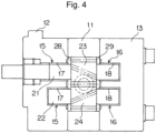
- FIG. 4 is a longitudinal cross-sectional view of a helical gear pump according to another embodiment of the present invention.
- a member similar to that in the embodiment illustrated in Figs. 1 to 3 is denoted by the same reference numeral, and omitted from detailed description.
- the bearing case 25 that houses the bush 15 and the bearing case 26 that houses the bush 16 are used as the pair of sliding contact members that sandwich an external gear pair including the helical gear 23 and the helical gear 24 from both sides.
- a configuration in which, in the bearing case 26 on the rear cover 13 side, the high-pressure hydraulic oil groove 27 communicating with the high-pressure region of the hydraulic fluid in the casing including the body 11, the front cover 12, and the rear cover 13 is formed, and the high-pressure hydraulic oil is supplied from the high-pressure hydraulic oil groove 27 toward the side surface of the helical gear 23 is employed.
- a pair of side plates (side plates) 28 and 29 are used as a pair of sliding contact members that sandwich an external gear pair including the helical gear 23 and the helical gear 24 from both sides.
- a configuration in which, on the side plate 29 on the rear cover 13 side, the high-pressure hydraulic oil groove 27 similar to that in Figs. 2 and 3 communicating with the high-pressure region of the hydraulic fluid in the casing including the body 11, the front cover 12, and the rear cover 13 is formed, and the high-pressure hydraulic oil is supplied from the high-pressure hydraulic oil groove 27 toward the side surface of the helical gear 23 is employed.
- one ends of the driving shaft 21 and the driven shaft 22 are each pivotally supported in the bearing hole 17 formed on the front cover 12 via the bush 15, and the other ends of the driving shaft 21 and the driven shaft 22 are each pivotally supported in the bearing hole 18 formed on the rear cover 13 via the bush 16.
- the pair of the bearing cases 25 and 26 or the pair of the side plates 28 and 29 are used as the sliding contact members.
- the configuration may be such that the pair of the bearing cases 25 and 26 or the pair of the side plates 28 and 29 are omitted, and the front cover 12 and the rear cover 13 are used as the sliding contact members.
- the high-pressure hydraulic oil groove 27 similar to that is Figs. 2 and 3 communicating with the high-pressure region of the hydraulic fluid in the casing including the body 11, the front cover 12, and the rear cover 13 is formed.
- the configuration may be such that, as the sliding contact member, one of the bearing case 25, the side plate 28, and the front cover 12 is used on one side surface of the external gear pair including the helical gear 23 and the helical gear 24, and one that is not used on the one side surface among the bearing case 25, the side plate 28, and the front cover 12 is used on the other side surface, so that they are used in a mixed manner.
- FIG. 5 is a longitudinal cross-sectional view of a helical gear pump according to still another embodiment of the present invention
- Fig. 6 is a cross-sectional arrow view taken along line A-A of Fig. 5
- Fig. 7 is an enlarged view illustrating an arrangement relationship between the high-pressure hydraulic oil groove 27 formed in the outer region of the driving shaft 21 in the bearing case 26, the helical gear 23, and the driving shaft 21.
- the high-pressure hydraulic oil groove 27 on the back side of the helical gear 23 is illustrated by a solid line.
- a member similar to that in the embodiment illustrated in Figs. 1 to 3 is denoted by the same reference numeral, and omitted from detailed description.
- the distance between the tooth bottom circle of the driving-side helical gear 23 and the bearing hole 18 of the driving shaft 21 is made larger than the distance between the tooth bottom circle of the driven-side helical gear 24 and the bearing hole 18 of the driven shaft 22.
- the helical gear pump according to the present embodiment employs a configuration in which the outer diameter of the driving shaft 21 in the region 21a penetrating the bearing case 26 on which the driving-side helical gear 23 is pressed among the bearing cases 25 and 26 as the pair of the sliding contact members is made smaller than the outer diameter of the driven shaft 22, so that the distance between the tooth bottom circle of the driving-side helical gear 23 and the bearing hole 18 in the region 21a of the driving shaft is made larger than the distance between the tooth bottom circle of the driven-side helical gear 24 and the bearing hole 18 of the driven shaft 22.
- the region on the side where the pair of the helical gears 23 and 24 start to mesh on the side surface of the pair of the helical gears 23 and 24 is the high-pressure region.
- the region of the outer peripheral portion of the driving shaft 21 and the driven shaft 22 on the side surface of the pair of the helical gears 23 and 24 is the low-pressure region.
- the high-pressure region and the low-pressure region are sealed by the tooth bottom seal region of the pair of the helical gears 23 and 24.
- the high-pressure hydraulic oil groove 27 is formed in the tooth bottom seal region of the helical gear 23 on the driving side.
- the outer diameter of the driving shaft in the region 21a penetrating the bearing case 26 on which the driving-side helical gear 23 is pressed is smaller than the outer diameter of the driven shaft 22.
- the distance between the tooth bottom circle of the driving-side helical gear 23 and the bearing hole 18 in the region 21a of the driving shaft can be made larger than the distance between the tooth bottom circle of the driven-side helical gear 24 and the bearing hole 18 of the driven shaft 22.
- the tooth bottom seal region of the helical gear 23 on the driving side (the region between the tooth bottom circle of the driving-side helical gear 23 and the bearing hole 18 in the region 21a of the driving shaft) is an extremely large region as compared with that in the conventional helical gear pump shown in Fig.
- the distance L3 (seal length) between the high-pressure region by the high-pressure hydraulic oil groove 27 and the low-pressure region by the outer peripheral portion of the driving shaft 21 can be set large. In this manner, a leakage flow rate of hydraulic oil from the high-pressure region to the low-pressure region on the side surface of the pair of the helical gears 23 and 24 can be suppressed.
- the embodiment illustrated in Figs. 5 to 7 employs the configuration in which the outer diameter of the driving shaft 21 in the region 21a penetrating the bearing case 26 on which the driving-side helical gear 23 is pressed is smaller than the outer diameter of the driven shaft 22.
- the outer diameter of the driving shaft 21 may be smaller than the outer diameter of the driven shaft 22 in the entire region.
- Each of the helical gear pumps according to the above-described embodiments can also function as a helical gear motor that exhibits a motor action of introducing high-pressure hydraulic oil from the discharge passage 33 so as to take out rotational torque from the driving shaft 21 to drive an external load, and discharging hydraulic oil having a constant pressure from the suction passage 32. That is, the helical gear pump in each of the above-described embodiments is also a helical gear motor.
- hydraulic oil is used as hydraulic fluid.
- hydraulic fluid other than hydraulic oil such as another type of liquid, fluid, or semifluid, may be used.
Landscapes
- Engineering & Computer Science (AREA)
- Mechanical Engineering (AREA)
- General Engineering & Computer Science (AREA)
- Rotary Pumps (AREA)
- Details And Applications Of Rotary Liquid Pumps (AREA)
- Hydraulic Motors (AREA)
Claims (5)
- Schrägzahnradpumpe oder -motor, umfassend:ein Paar Außenzahnräder, einschließlich eines antriebsseitigen Schrägzahnrads und eines abtriebsseitigen Schrägzahnrads, die miteinander kämmen;ein Paar Gleitkontaktelemente, an denen Lagerlöcher einer Antriebswelle, die mit dem antriebsseitigen Schrägzahnrad verbunden ist, und Lagerlöcher einer Abtriebswelle, die mit dem abtriebsseitigen Schrägzahnrad verbunden ist, ausgebildet sind, wobei das Paar Gleitkontaktelemente das Paar Außenzahnräder von beiden Seiten einschließt;ein Gehäuse, dazu konfiguriert, das Paar Außenzahnräder und das Paar Gleitkontaktelemente aufzunehmen; undeine Nut für Hochdruckhydraulikfluid, die in einem Anlagebereich zwischen dem antriebsseitigen Schrägzahnrad und einem Gleitkontaktelement ausgebildet ist, auf das das antriebsseitige Schrägzahnrad zwischen dem Paar Gleitkontaktelemente gedrückt wird, wobei die Nut für Hochdruckhydraulikfluid mit einem Hochdruckbereich für Hydraulikfluid im Gehäuse in Verbindung steht, dadurch gekennzeichnet, dassein Abstand zwischen einem Zahngrundkreis des antriebsseitigen Schrägzahnrads und einem Lagerloch der Antriebswelle ist größer eingestellt als ein Abstand zwischen einem Zahngrundkreis des abtriebsseitigen Schrägzahnrads und einem Lagerloch der Abtriebswelle.
- Schrägzahnradpumpe oder-motor nach Anspruch 1, wobei
die Anzahl der Zähne des antriebsseitigen Schrägzahnrads größer gewählt ist als die Anzahl der Zähne des abtriebsseitigen Schrägzahnrads. - Schrägzahnradpumpe oder-motor nach Anspruch 1, wobei
ein Außendurchmesser der Antriebswelle in einem das Gleitkontaktelement durchdringenden Bereich, auf den das antriebsseitige Schrägzahnrad zwischen dem Paar Gleitkontaktelemente gedrückt wird, kleiner ist als ein Außendurchmesser der Abtriebswelle. - Schrägzahnradpumpe oder -motor nach einem der Ansprüche 1 bis 3, wobei das Gleitkontaktelement ein Lagergehäuse oder eine Seitenplatte ist.
- Schrägzahnradpumpe oder-motor nach einem der Ansprüche 1 bis 4, wobei
im Vergleich zu einem Fall, in dem der Abstand zwischen dem Zahngrundkreis des antriebsseitigen Schrägzahnrads und dem Lagerloch der Antriebswelle höchstens so groß eingestellt ist wie der Abstand zwischen dem Zahngrundkreis des abtriebsseitigen Schrägzahnrads und dem Lagerloch der Abtriebswelle, ein Abstand zwischen einem Hochdruckbereich durch die Nut für Hochdruckhydraulikfluid und einem Niederdruckbereich durch einen äußeren Umfangsabschnitt der Antriebswelle groß eingestellt ist.
Applications Claiming Priority (1)
| Application Number | Priority Date | Filing Date | Title |
|---|---|---|---|
| PCT/JP2019/009492 WO2020183546A1 (ja) | 2019-03-08 | 2019-03-08 | はすば歯車ポンプまたはモータ |
Publications (3)
| Publication Number | Publication Date |
|---|---|
| EP3936725A1 EP3936725A1 (de) | 2022-01-12 |
| EP3936725A4 EP3936725A4 (de) | 2022-03-23 |
| EP3936725B1 true EP3936725B1 (de) | 2024-12-04 |
Family
ID=72426956
Family Applications (1)
| Application Number | Title | Priority Date | Filing Date |
|---|---|---|---|
| EP19919109.9A Active EP3936725B1 (de) | 2019-03-08 | 2019-03-08 | Schraubenradpumpe oder -motor |
Country Status (5)
| Country | Link |
|---|---|
| US (1) | US11773845B2 (de) |
| EP (1) | EP3936725B1 (de) |
| JP (1) | JP7124954B2 (de) |
| CN (1) | CN113348303B (de) |
| WO (1) | WO2020183546A1 (de) |
Families Citing this family (1)
| Publication number | Priority date | Publication date | Assignee | Title |
|---|---|---|---|---|
| US11378076B1 (en) * | 2021-01-28 | 2022-07-05 | Shimadzu Corporation | Gear pump or motor |
Citations (6)
| Publication number | Priority date | Publication date | Assignee | Title |
|---|---|---|---|---|
| GB850783A (en) * | 1958-06-23 | 1960-10-05 | Nat Res Dev | Hydrostatic power transmission systems |
| FR2296778A1 (fr) * | 1975-01-03 | 1976-07-30 | Rexroth Sigma | Perfectionnements apportes aux machines a pistons radiaux, notamment aux moteurs ou pompes hydrauliques |
| JP2002206475A (ja) * | 2001-01-09 | 2002-07-26 | Nagatomo Ryutai Kikai Kenkyusho:Kk | 複列型ラジアルピストンポンプ |
| US7204565B2 (en) * | 2004-05-13 | 2007-04-17 | Continental Teves Ag & Co. Ohg | Electrohydraulic assembly for an electronically controlled brake system |
| CN201546889U (zh) * | 2009-08-07 | 2010-08-11 | 佛山市顺德区中意液压有限公司 | 双列径向十柱塞马达 |
| WO2017098250A1 (en) * | 2015-12-08 | 2017-06-15 | Domin Fluid Power Limited | Radial pumps and motors |
Family Cites Families (13)
| Publication number | Priority date | Publication date | Assignee | Title |
|---|---|---|---|---|
| JP3972072B2 (ja) * | 1994-07-07 | 2007-09-05 | デイヴィッド ブラウン ハイドロリックス リミテッド | 流体圧装置 |
| JP3727474B2 (ja) * | 1998-08-28 | 2005-12-14 | 株式会社ノリタケカンパニーリミテド | 振動防止機構及び振動防止機構を備えた工作機械 |
| JP2002070754A (ja) * | 2000-09-01 | 2002-03-08 | Shimadzu Corp | 歯車ポンプ又はモータ |
| JP4200919B2 (ja) * | 2004-02-17 | 2008-12-24 | 株式会社Ihi | ギアポンプ |
| WO2007052332A1 (ja) * | 2005-10-31 | 2007-05-10 | Mayekawa Mfg. Co., Ltd | 液噴射式スクリュー圧縮機 |
| DE102009012916A1 (de) | 2009-03-12 | 2010-09-16 | Robert Bosch Gmbh | Hydraulische Zahnradmaschine |
| DE102009047610A1 (de) * | 2009-12-08 | 2011-06-09 | Robert Bosch Gmbh | Außenzahnradpumpe |
| CN201661316U (zh) * | 2010-02-08 | 2010-12-01 | 中国海洋石油总公司 | 一种高温齿轮液压马达 |
| JP2013234635A (ja) * | 2012-05-11 | 2013-11-21 | Toyota Industries Corp | 外接ギヤポンプ |
| WO2014141377A1 (ja) | 2013-03-12 | 2014-09-18 | 株式会社 島津製作所 | 歯車ポンプ又はモータ |
| KR102453608B1 (ko) * | 2016-05-11 | 2022-10-12 | 현대두산인프라코어(주) | 기어펌프 |
| CN105952637A (zh) * | 2016-06-16 | 2016-09-21 | 江苏国瑞液压机械有限公司 | 一种大排量主、从动轮大小不同的高压齿轮泵 |
| DE102017218315A1 (de) * | 2017-10-13 | 2019-04-18 | Robert Bosch Gmbh | Außenzahnradpumpe für ein Abwärmerückgewinnungssystem |
-
2019
- 2019-03-08 JP JP2021504628A patent/JP7124954B2/ja active Active
- 2019-03-08 EP EP19919109.9A patent/EP3936725B1/de active Active
- 2019-03-08 CN CN201980090385.6A patent/CN113348303B/zh active Active
- 2019-03-08 US US17/428,627 patent/US11773845B2/en active Active
- 2019-03-08 WO PCT/JP2019/009492 patent/WO2020183546A1/ja not_active Ceased
Patent Citations (6)
| Publication number | Priority date | Publication date | Assignee | Title |
|---|---|---|---|---|
| GB850783A (en) * | 1958-06-23 | 1960-10-05 | Nat Res Dev | Hydrostatic power transmission systems |
| FR2296778A1 (fr) * | 1975-01-03 | 1976-07-30 | Rexroth Sigma | Perfectionnements apportes aux machines a pistons radiaux, notamment aux moteurs ou pompes hydrauliques |
| JP2002206475A (ja) * | 2001-01-09 | 2002-07-26 | Nagatomo Ryutai Kikai Kenkyusho:Kk | 複列型ラジアルピストンポンプ |
| US7204565B2 (en) * | 2004-05-13 | 2007-04-17 | Continental Teves Ag & Co. Ohg | Electrohydraulic assembly for an electronically controlled brake system |
| CN201546889U (zh) * | 2009-08-07 | 2010-08-11 | 佛山市顺德区中意液压有限公司 | 双列径向十柱塞马达 |
| WO2017098250A1 (en) * | 2015-12-08 | 2017-06-15 | Domin Fluid Power Limited | Radial pumps and motors |
Also Published As
| Publication number | Publication date |
|---|---|
| JPWO2020183546A1 (ja) | 2021-11-04 |
| CN113348303B (zh) | 2023-02-21 |
| WO2020183546A1 (ja) | 2020-09-17 |
| EP3936725A1 (de) | 2022-01-12 |
| US20220112894A1 (en) | 2022-04-14 |
| US11773845B2 (en) | 2023-10-03 |
| JP7124954B2 (ja) | 2022-08-24 |
| CN113348303A (zh) | 2021-09-03 |
| EP3936725A4 (de) | 2022-03-23 |
Similar Documents
| Publication | Publication Date | Title |
|---|---|---|
| EP2859237B1 (de) | Zahnradpumpe oder hydraulischer zahnradmotor mit spiralverzahnung mit hydraulischem system zur axialschubausgleich | |
| EP2837827B1 (de) | Hydaulische vorrichtung | |
| US2344628A (en) | Gear pump | |
| EP1988290B2 (de) | Zahnradpumpe | |
| EP0749532B1 (de) | Lager für zahnradpumpe | |
| US20050020401A1 (en) | Gear mechanism and reduction planetary gear | |
| EP3936725B1 (de) | Schraubenradpumpe oder -motor | |
| US20040071559A1 (en) | Integrated speed reducer and pump assembly | |
| EP3521622B1 (de) | Zahnradpumpe oder getriebemotor | |
| US20070099747A1 (en) | Gear mechanism and reduction planetary gear | |
| CN118273947A (zh) | 内啮合齿轮泵、集成式电机泵和车辆 | |
| JP6119748B2 (ja) | 歯車ポンプ又はモータ | |
| EP2789854B1 (de) | Flüssigkeitsdruckvorrichtung | |
| EP2447533B1 (de) | Getriebepumpe | |
| EP2581253A1 (de) | Radantriebsdrehzahlreduzierer | |
| WO2014136186A1 (ja) | 歯車ポンプ又はモータ | |
| US20210215240A1 (en) | Differential device | |
| JP2004028005A (ja) | 内接歯車式オイルポンプおよびこれを備えた自動変速機 | |
| JP2007218128A (ja) | ギヤポンプ | |
| CN214403970U (zh) | 一种带补偿的内啮合摆线转子泵或马达 | |
| WO2014141377A1 (ja) | 歯車ポンプ又はモータ | |
| JP6625867B2 (ja) | 液圧装置 | |
| CN216742658U (zh) | 一种小型化摆线减速装置 | |
| US20170335846A1 (en) | Gear Pump | |
| JP2002202070A (ja) | ギヤポンプ |
Legal Events
| Date | Code | Title | Description |
|---|---|---|---|
| STAA | Information on the status of an ep patent application or granted ep patent |
Free format text: STATUS: THE INTERNATIONAL PUBLICATION HAS BEEN MADE |
|
| PUAI | Public reference made under article 153(3) epc to a published international application that has entered the european phase |
Free format text: ORIGINAL CODE: 0009012 |
|
| STAA | Information on the status of an ep patent application or granted ep patent |
Free format text: STATUS: REQUEST FOR EXAMINATION WAS MADE |
|
| 17P | Request for examination filed |
Effective date: 20210715 |
|
| AK | Designated contracting states |
Kind code of ref document: A1 Designated state(s): AL AT BE BG CH CY CZ DE DK EE ES FI FR GB GR HR HU IE IS IT LI LT LU LV MC MK MT NL NO PL PT RO RS SE SI SK SM TR |
|
| A4 | Supplementary search report drawn up and despatched |
Effective date: 20220217 |
|
| RIC1 | Information provided on ipc code assigned before grant |
Ipc: F04C 15/00 20060101ALI20220211BHEP Ipc: F04C 2/16 20060101ALI20220211BHEP Ipc: F04C 18/16 20060101AFI20220211BHEP |
|
| DAV | Request for validation of the european patent (deleted) | ||
| DAX | Request for extension of the european patent (deleted) | ||
| GRAP | Despatch of communication of intention to grant a patent |
Free format text: ORIGINAL CODE: EPIDOSNIGR1 |
|
| STAA | Information on the status of an ep patent application or granted ep patent |
Free format text: STATUS: GRANT OF PATENT IS INTENDED |
|
| INTG | Intention to grant announced |
Effective date: 20240801 |
|
| GRAS | Grant fee paid |
Free format text: ORIGINAL CODE: EPIDOSNIGR3 |
|
| GRAA | (expected) grant |
Free format text: ORIGINAL CODE: 0009210 |
|
| STAA | Information on the status of an ep patent application or granted ep patent |
Free format text: STATUS: THE PATENT HAS BEEN GRANTED |
|
| AK | Designated contracting states |
Kind code of ref document: B1 Designated state(s): AL AT BE BG CH CY CZ DE DK EE ES FI FR GB GR HR HU IE IS IT LI LT LU LV MC MK MT NL NO PL PT RO RS SE SI SK SM TR |
|
| REG | Reference to a national code |
Ref country code: CH Ref legal event code: EP |
|
| REG | Reference to a national code |
Ref country code: DE Ref legal event code: R096 Ref document number: 602019063217 Country of ref document: DE |
|
| REG | Reference to a national code |
Ref country code: IE Ref legal event code: FG4D |
|
| REG | Reference to a national code |
Ref country code: LT Ref legal event code: MG9D |
|
| REG | Reference to a national code |
Ref country code: NL Ref legal event code: MP Effective date: 20241204 |
|
| PG25 | Lapsed in a contracting state [announced via postgrant information from national office to epo] |
Ref country code: HR Free format text: LAPSE BECAUSE OF FAILURE TO SUBMIT A TRANSLATION OF THE DESCRIPTION OR TO PAY THE FEE WITHIN THE PRESCRIBED TIME-LIMIT Effective date: 20241204 |
|
| PG25 | Lapsed in a contracting state [announced via postgrant information from national office to epo] |
Ref country code: FI Free format text: LAPSE BECAUSE OF FAILURE TO SUBMIT A TRANSLATION OF THE DESCRIPTION OR TO PAY THE FEE WITHIN THE PRESCRIBED TIME-LIMIT Effective date: 20241204 |
|
| PG25 | Lapsed in a contracting state [announced via postgrant information from national office to epo] |
Ref country code: BG Free format text: LAPSE BECAUSE OF FAILURE TO SUBMIT A TRANSLATION OF THE DESCRIPTION OR TO PAY THE FEE WITHIN THE PRESCRIBED TIME-LIMIT Effective date: 20241204 |
|
| PG25 | Lapsed in a contracting state [announced via postgrant information from national office to epo] |
Ref country code: ES Free format text: LAPSE BECAUSE OF FAILURE TO SUBMIT A TRANSLATION OF THE DESCRIPTION OR TO PAY THE FEE WITHIN THE PRESCRIBED TIME-LIMIT Effective date: 20241204 |
|
| PG25 | Lapsed in a contracting state [announced via postgrant information from national office to epo] |
Ref country code: NO Free format text: LAPSE BECAUSE OF FAILURE TO SUBMIT A TRANSLATION OF THE DESCRIPTION OR TO PAY THE FEE WITHIN THE PRESCRIBED TIME-LIMIT Effective date: 20250304 |
|
| PG25 | Lapsed in a contracting state [announced via postgrant information from national office to epo] |
Ref country code: GR Free format text: LAPSE BECAUSE OF FAILURE TO SUBMIT A TRANSLATION OF THE DESCRIPTION OR TO PAY THE FEE WITHIN THE PRESCRIBED TIME-LIMIT Effective date: 20250305 Ref country code: LV Free format text: LAPSE BECAUSE OF FAILURE TO SUBMIT A TRANSLATION OF THE DESCRIPTION OR TO PAY THE FEE WITHIN THE PRESCRIBED TIME-LIMIT Effective date: 20241204 |
|
| PG25 | Lapsed in a contracting state [announced via postgrant information from national office to epo] |
Ref country code: RS Free format text: LAPSE BECAUSE OF FAILURE TO SUBMIT A TRANSLATION OF THE DESCRIPTION OR TO PAY THE FEE WITHIN THE PRESCRIBED TIME-LIMIT Effective date: 20250304 |
|
| PG25 | Lapsed in a contracting state [announced via postgrant information from national office to epo] |
Ref country code: NL Free format text: LAPSE BECAUSE OF FAILURE TO SUBMIT A TRANSLATION OF THE DESCRIPTION OR TO PAY THE FEE WITHIN THE PRESCRIBED TIME-LIMIT Effective date: 20241204 |
|
| REG | Reference to a national code |
Ref country code: AT Ref legal event code: MK05 Ref document number: 1748431 Country of ref document: AT Kind code of ref document: T Effective date: 20241204 |
|
| PG25 | Lapsed in a contracting state [announced via postgrant information from national office to epo] |
Ref country code: SM Free format text: LAPSE BECAUSE OF FAILURE TO SUBMIT A TRANSLATION OF THE DESCRIPTION OR TO PAY THE FEE WITHIN THE PRESCRIBED TIME-LIMIT Effective date: 20241204 |
|
| PG25 | Lapsed in a contracting state [announced via postgrant information from national office to epo] |
Ref country code: PL Free format text: LAPSE BECAUSE OF FAILURE TO SUBMIT A TRANSLATION OF THE DESCRIPTION OR TO PAY THE FEE WITHIN THE PRESCRIBED TIME-LIMIT Effective date: 20241204 |
|
| PG25 | Lapsed in a contracting state [announced via postgrant information from national office to epo] |
Ref country code: IS Free format text: LAPSE BECAUSE OF FAILURE TO SUBMIT A TRANSLATION OF THE DESCRIPTION OR TO PAY THE FEE WITHIN THE PRESCRIBED TIME-LIMIT Effective date: 20250404 |
|
| PG25 | Lapsed in a contracting state [announced via postgrant information from national office to epo] |
Ref country code: PT Free format text: LAPSE BECAUSE OF FAILURE TO SUBMIT A TRANSLATION OF THE DESCRIPTION OR TO PAY THE FEE WITHIN THE PRESCRIBED TIME-LIMIT Effective date: 20250404 |
|
| PG25 | Lapsed in a contracting state [announced via postgrant information from national office to epo] |
Ref country code: EE Free format text: LAPSE BECAUSE OF FAILURE TO SUBMIT A TRANSLATION OF THE DESCRIPTION OR TO PAY THE FEE WITHIN THE PRESCRIBED TIME-LIMIT Effective date: 20241204 |
|
| PG25 | Lapsed in a contracting state [announced via postgrant information from national office to epo] |
Ref country code: AT Free format text: LAPSE BECAUSE OF FAILURE TO SUBMIT A TRANSLATION OF THE DESCRIPTION OR TO PAY THE FEE WITHIN THE PRESCRIBED TIME-LIMIT Effective date: 20241204 Ref country code: RO Free format text: LAPSE BECAUSE OF FAILURE TO SUBMIT A TRANSLATION OF THE DESCRIPTION OR TO PAY THE FEE WITHIN THE PRESCRIBED TIME-LIMIT Effective date: 20241204 |
|
| PG25 | Lapsed in a contracting state [announced via postgrant information from national office to epo] |
Ref country code: SK Free format text: LAPSE BECAUSE OF FAILURE TO SUBMIT A TRANSLATION OF THE DESCRIPTION OR TO PAY THE FEE WITHIN THE PRESCRIBED TIME-LIMIT Effective date: 20241204 |
|
| PG25 | Lapsed in a contracting state [announced via postgrant information from national office to epo] |
Ref country code: CZ Free format text: LAPSE BECAUSE OF FAILURE TO SUBMIT A TRANSLATION OF THE DESCRIPTION OR TO PAY THE FEE WITHIN THE PRESCRIBED TIME-LIMIT Effective date: 20241204 |
|
| PG25 | Lapsed in a contracting state [announced via postgrant information from national office to epo] |
Ref country code: IT Free format text: LAPSE BECAUSE OF FAILURE TO SUBMIT A TRANSLATION OF THE DESCRIPTION OR TO PAY THE FEE WITHIN THE PRESCRIBED TIME-LIMIT Effective date: 20241204 |
|
| REG | Reference to a national code |
Ref country code: DE Ref legal event code: R097 Ref document number: 602019063217 Country of ref document: DE |
|
| PG25 | Lapsed in a contracting state [announced via postgrant information from national office to epo] |
Ref country code: SE Free format text: LAPSE BECAUSE OF FAILURE TO SUBMIT A TRANSLATION OF THE DESCRIPTION OR TO PAY THE FEE WITHIN THE PRESCRIBED TIME-LIMIT Effective date: 20241204 |
|
| PG25 | Lapsed in a contracting state [announced via postgrant information from national office to epo] |
Ref country code: DK Free format text: LAPSE BECAUSE OF FAILURE TO SUBMIT A TRANSLATION OF THE DESCRIPTION OR TO PAY THE FEE WITHIN THE PRESCRIBED TIME-LIMIT Effective date: 20241204 |
|
| PLBE | No opposition filed within time limit |
Free format text: ORIGINAL CODE: 0009261 |
|
| STAA | Information on the status of an ep patent application or granted ep patent |
Free format text: STATUS: NO OPPOSITION FILED WITHIN TIME LIMIT |
|
| PG25 | Lapsed in a contracting state [announced via postgrant information from national office to epo] |
Ref country code: MC Free format text: LAPSE BECAUSE OF FAILURE TO SUBMIT A TRANSLATION OF THE DESCRIPTION OR TO PAY THE FEE WITHIN THE PRESCRIBED TIME-LIMIT Effective date: 20241204 |
|
| REG | Reference to a national code |
Ref country code: CH Ref legal event code: L10 Free format text: ST27 STATUS EVENT CODE: U-0-0-L10-L00 (AS PROVIDED BY THE NATIONAL OFFICE) Effective date: 20251015 |
|
| REG | Reference to a national code |
Ref country code: CH Ref legal event code: H13 Free format text: ST27 STATUS EVENT CODE: U-0-0-H10-H13 (AS PROVIDED BY THE NATIONAL OFFICE) Effective date: 20251023 |
|
| 26N | No opposition filed |
Effective date: 20250905 |
|
| PG25 | Lapsed in a contracting state [announced via postgrant information from national office to epo] |
Ref country code: LU Free format text: LAPSE BECAUSE OF NON-PAYMENT OF DUE FEES Effective date: 20250308 |
|
| GBPC | Gb: european patent ceased through non-payment of renewal fee |
Effective date: 20250308 |
|
| REG | Reference to a national code |
Ref country code: BE Ref legal event code: MM Effective date: 20250331 |
|
| PG25 | Lapsed in a contracting state [announced via postgrant information from national office to epo] |
Ref country code: GB Free format text: LAPSE BECAUSE OF NON-PAYMENT OF DUE FEES Effective date: 20250308 |
|
| PG25 | Lapsed in a contracting state [announced via postgrant information from national office to epo] |
Ref country code: FR Free format text: LAPSE BECAUSE OF NON-PAYMENT OF DUE FEES Effective date: 20250331 |
|
| PG25 | Lapsed in a contracting state [announced via postgrant information from national office to epo] |
Ref country code: BE Free format text: LAPSE BECAUSE OF NON-PAYMENT OF DUE FEES Effective date: 20250331 |
|
| PG25 | Lapsed in a contracting state [announced via postgrant information from national office to epo] |
Ref country code: CH Free format text: LAPSE BECAUSE OF NON-PAYMENT OF DUE FEES Effective date: 20250331 |
|
| PG25 | Lapsed in a contracting state [announced via postgrant information from national office to epo] |
Ref country code: IE Free format text: LAPSE BECAUSE OF NON-PAYMENT OF DUE FEES Effective date: 20250308 |
|
| PGFP | Annual fee paid to national office [announced via postgrant information from national office to epo] |
Ref country code: DE Payment date: 20260128 Year of fee payment: 8 |