EP3936770B1 - Système de chauffage à équilibrage hydraulique adaptatif automatique - Google Patents
Système de chauffage à équilibrage hydraulique adaptatif automatique Download PDFInfo
- Publication number
- EP3936770B1 EP3936770B1 EP21020410.3A EP21020410A EP3936770B1 EP 3936770 B1 EP3936770 B1 EP 3936770B1 EP 21020410 A EP21020410 A EP 21020410A EP 3936770 B1 EP3936770 B1 EP 3936770B1
- Authority
- EP
- European Patent Office
- Prior art keywords
- heating
- control unit
- valve
- value
- room temperature
- Prior art date
- Legal status (The legal status is an assumption and is not a legal conclusion. Google has not performed a legal analysis and makes no representation as to the accuracy of the status listed.)
- Active
Links
Images

Classifications
-
- F—MECHANICAL ENGINEERING; LIGHTING; HEATING; WEAPONS; BLASTING
- F24—HEATING; RANGES; VENTILATING
- F24D—DOMESTIC- OR SPACE-HEATING SYSTEMS, e.g. CENTRAL HEATING SYSTEMS; DOMESTIC HOT-WATER SUPPLY SYSTEMS; ELEMENTS OR COMPONENTS THEREFOR
- F24D19/00—Details
- F24D19/10—Arrangement or mounting of control or safety devices
- F24D19/1006—Arrangement or mounting of control or safety devices for water heating systems
- F24D19/1009—Arrangement or mounting of control or safety devices for water heating systems for central heating
- F24D19/1015—Arrangement or mounting of control or safety devices for water heating systems for central heating using a valve or valves
- F24D19/1036—Having differential pressure measurement facilities
-
- G—PHYSICS
- G05—CONTROLLING; REGULATING
- G05D—SYSTEMS FOR CONTROLLING OR REGULATING NON-ELECTRIC VARIABLES
- G05D23/00—Control of temperature
- G05D23/19—Control of temperature characterised by the use of electric means
- G05D23/1917—Control of temperature characterised by the use of electric means using digital means
-
- G—PHYSICS
- G06—COMPUTING OR CALCULATING; COUNTING
- G06N—COMPUTING ARRANGEMENTS BASED ON SPECIFIC COMPUTATIONAL MODELS
- G06N3/00—Computing arrangements based on biological models
- G06N3/02—Neural networks
- G06N3/04—Architecture, e.g. interconnection topology
- G06N3/0499—Feedforward networks
-
- G—PHYSICS
- G06—COMPUTING OR CALCULATING; COUNTING
- G06N—COMPUTING ARRANGEMENTS BASED ON SPECIFIC COMPUTATIONAL MODELS
- G06N3/00—Computing arrangements based on biological models
- G06N3/02—Neural networks
- G06N3/08—Learning methods
- G06N3/09—Supervised learning
-
- F—MECHANICAL ENGINEERING; LIGHTING; HEATING; WEAPONS; BLASTING
- F24—HEATING; RANGES; VENTILATING
- F24D—DOMESTIC- OR SPACE-HEATING SYSTEMS, e.g. CENTRAL HEATING SYSTEMS; DOMESTIC HOT-WATER SUPPLY SYSTEMS; ELEMENTS OR COMPONENTS THEREFOR
- F24D2220/00—Components of central heating installations excluding heat sources
- F24D2220/02—Fluid distribution means
- F24D2220/0264—Hydraulic balancing valves
-
- G—PHYSICS
- G06—COMPUTING OR CALCULATING; COUNTING
- G06N—COMPUTING ARRANGEMENTS BASED ON SPECIFIC COMPUTATIONAL MODELS
- G06N3/00—Computing arrangements based on biological models
- G06N3/02—Neural networks
- G06N3/08—Learning methods
Definitions
- the invention relates to a heating system with an automatic, adaptive, hydraulic balancing as well as a method for carrying out an automatic, adaptive hydraulic balancing in a heating system and a method for training an artificial neural network.
- Each of the documents DE 10 2012 018778 A1 , EP 1 936 288 A2 or DE 10 2011 018698 A1 shows a heating system with automatic adaptive hydraulic balancing according to the state of the art.
- the invention has set itself the task of providing a heating system in which an adaptive hydraulic balance is automatically achieved between the consumers, ie the radiators.
- the heating valve is adjusted by a computer unit and based on the desired target temperature for the respective room in such a way that an adapted, i.e. adaptive, setting of the room temperature can be achieved in an optimized manner via the optimized setting of the heating valve position.
- the balancing is carried out continuously during operation or at defined intervals.
- the balancing systems are automatically adjusted initially and repeatedly/continuously during operation.
- a target value e.g. target water flow
- a continuously acting control device by an algorithm based on measured variables (e.g. differential pressure, flow, temperature), whereby changing operating conditions in the hydraulic system (e.g. differential pressure, temperature) are reacted to during operation, with the aim of avoiding exceeding the target value specified by the algorithm in the design and partial load case.
- measured variables e.g. differential pressure, flow, temperature
- Hydraulic actuator e.g. of the room temperature control circuit and/or balancing system - for influencing the flow of media (blocking, letting through, regulating).
- actuators with corresponding functionality are called valves regardless of their technical structure.
- the present invention relates primarily to heating systems.
- the statements contained therein - in particular temperature-based optimization strategies - can be transferred in part to cooling and heating-cooling hybrid systems, which are thus equally covered by the invention.
- Such cooling systems are, for example, cold transfer devices - in particular surface cooling systems - or hybrid systems that use the same hydraulic system for heating and cooling.
- the heating system according to the invention with an automatic adaptive hydraulic balancing of several apartments comprises at least one central heating source, for example a burner, a solar thermal module or comparable devices for generating heating energy. It is also conceivable that heating energy is made available via a district heating facility that supplies several consumers.
- the heating system also comprises at least one first consumer, for example a radiator or underfloor heating, each with a local flow branch and a local return branch, at least one central circulation pump for conveying a heating medium from the heating source via a central flow line to the first consumer. The heating medium can then flow from the first consumer back to the heating source via a central return line.
- a first heating valve in particular a thermostatic valve, assigned to the first consumer and arranged in the respective flow branch is provided with a first actuator assigned to the first heating valve and equipped with first control and feedback electronics for setting a valve position value for controlling a volume flow of the heating medium in the first consumer, wherein the actuator preferably acts on an actuating pin of the heating valve.
- the heating system also has a recording device for an ACTUAL VALUE of the room temperature and a control unit coupled to the recording device and the first actuator.
- a TARGET value for the room temperature can be stored in the control unit and a control signal for the valve position value can be output to the control and feedback electronics via the control unit, after which the TARGET value for the room temperature can be set by incrementally operating the actuator.
- the control unit is either a decentralized or centralized unit that is able to record the values for the ACTUAL temperature to compare with the values for the target room temperature and to derive a control signal from this, which is then output to the control and feedback electronics.
- the control unit can be provided as a physical element in the room to be heated, in a house or a building complex. At the same time, it is also possible to provide a virtual control unit, for example on a server. Cloud solutions are also included.
- the term TARGET value for the room temperature refers to the room temperature value that is either set by the user or stored in a temperature profile. This temperature profile can, for example, provide for different room temperatures over the course of the day.
- the heating system sets these temperatures independently, automatically and regularly or continuously checks the ACTUAL temperature value in order to compare it with a TARGET value.
- the set valve position value can be returned to the control unit via the control and feedback electronics.
- the adaptive hydraulic balancing can thus be carried out by time-controlled, in particular continuous and preferably automatic adjustment of the valve position value.
- the heating system according to the invention therefore does not require an initial setting of the heating valves. This makes setting up and starting up the heating system much easier.
- the heating system according to the invention is able to react continuously and dynamically to temperature changes and can also continuously set, monitor and, if necessary, readjust temperature profiles stored in the control unit. It is also possible to control different temperatures or temperature profiles in different rooms.
- Adaptive balancing systems adjust the limitation of flow rates to the current demand. Characteristic features are the automatic and continuous or repeated determination of the respective target temperature value to be maintained depending on the current operating status and demand of all balancing devices/transfer devices and the pressure-independent control to ensure that the target value is not exceeded.
- the complete balancing system including measuring and evaluation devices, is permanently installed in the hydraulic Integrated into the system or connected to it.
- the temperature-based adaptive hydraulic balancing is essentially based on the measurement and evaluation of media and/or room temperatures.
- a preferred development of the heating system according to the invention provides that at least one second consumer is provided and the control unit for setting the nominal value for the room temperature outputs control signals for setting the respective valve position value to the control and feedback electronics of the respective consumer. After the valve position values of the first and second consumer have been compared, the control unit outputs individual valve position values to the control and feedback electronics of the first and second consumer for setting the room temperature. In the heating system, a comparison can thus be made between different consumers and the adjustment of the individual consumers can be carried out based on this adjustment. The system is therefore much more flexible overall and can also take other influencing factors into account.
- the control is essentially carried out via the recorded ACTUAL temperature in the room and its adjustment with the desired or required nominal temperature.
- a preferred embodiment of the heating system according to the invention provides that the consumers are arranged in separate rooms and a connection is provided directly with a central control unit or via a control unit assigned to each consumer.
- a decentralized control unit based on rooms that is only connected to one or a few consumers in addition to a central control unit, i.e. one that combines several consumption units. It is also possible to bundle the decentralized control units and to control the heating system of larger complexes at a higher level via a server-based solution for the control unit or control units.
- a special form of the heating system according to the invention is underfloor heating.
- several valves are arranged on a distributor, which regulate the individual heating circuits of the underfloor heating.
- the housing is designed so that the valves of the individual heating circuits adjust to one another and thus the same temperature is set across the board in all connected heating circuits.
- additional temperature sensors can be installed on the return or flow lines. of the individual heating circuits of the underfloor heating, which enable an exact adjustment of the temperature, since further measured values are derived from this, which are returned to the control unit and included there in the adjustment of the valve setting value, taking into account the values from the room thermostats or sensors in the building.
- the control units also enable communication between the individual valves on the distributor.
- Several actuators of valves in an underfloor distributor can be controlled simultaneously via a single control unit.
- a further development of the invention provides that the heating system is integrated into a distribution network having several sections, whereby the sections have independent heating lines, each with at least one heating system. A comparison between the heating systems via the control units in the individual heating lines or individual heating systems is also provided here.
- the distribution network in the heating system according to the invention has at least one network control unit for automatic dynamic hydraulic balancing in the entire distribution network.
- the network control unit can control the heating systems individually, i.e. independently of one another, or after a higher-level balancing, directly or indirectly via the control units of the respective heating systems or via central control units, for example of individual heating lines.
- the heating system is controlled in accordance with the present invention based on temperature.
- a thermal time behavior i.e. a defined course of the room temperature, for example based on daily or seasonal conditions, can be set via retrievable target value profiles for the room temperature in the network control unit, the central control units and/or the control units of individual units of the heating system, and the automatic adaptive hydraulic balancing can be carried out depending on these target value profiles.
- the control unit is able to compare the recorded ACTUAL temperature with the DESIRED temperature, taking into account the additional influencing factors, and then derive a valve position value from this and output it to the individual heating valves of the respective consumers.
- the heating system according to the invention is characterized in a preferred embodiment in that the actuator is designed as a stepper motor.
- This stepper motor preferably has a step resolution of between 0 and 1000 steps, in particular between 0 and 800 steps, preferably between 0 and 600 steps, particularly preferably between 0 and 300 steps, and thus allows incremental adjustment with high resolution.
- the stepper motor can be provided independently of the valve.
- the stepper motor can also be combined with standard valves and can also be subsequently added to existing valves, thus providing the option of retrofitting existing valves.
- the heating valve is designed as a stepper motor valve and the actuator is provided as part of the stepper motor valve.
- a target temperature ramp is provided that specifies the speed within which the target values for the room temperature are reached.
- the actuation speed of the actuator is also controlled depending on the target temperature ramp. This can be particularly useful when comparing several rooms with different initial or actual temperatures, which are to reach the required target temperature at the same time at a defined target time.
- a detection device for the room temperature is provided.
- the detection device is provided as an independent unit, for example as a measuring sensor or room thermostat.
- the detection device can also be arranged directly in the heating valve or in a room thermostat or one or more measuring sensors arranged in the room.
- the detection device is thus either an integrated or as a stand-alone or independent temperature measuring device. designed and either part of the control unit or linked to it for data purposes.
- the detection device it is possible for the detection device to also include a sensor for room usage. This means that the entire system is only activated when the room is being used in a certain, predefined way.
- the room temperature is only regulated by the heating system according to the invention when there is a certain activity in the room. This rules out the possibility that, for example, pets moving around the room act as a trigger for the heating system to activate.
- the heating system is also not activated when people are resting, for example during a sleep phase, because the sensor is able to distinguish between the corresponding activities and, based on these and a stored movement profile, outputs an activation signal to the heating system.
- the coupling of detection devices, actuators and the respective control unit is provided wirelessly, in particular via Wi-Fi, radio, Bluetooth or a telephone or mobile network.
- Wi-Fi Wireless Fidelity
- radio Wireless Fidelity
- Bluetooth Wireless Fidelity
- a direct connection to a router or the connection via a so-called gateway can also be made.
- the respective network control unit, the control unit and/or the central control unit is arranged decentrally and/or integrated into a data network.
- the respective data acquisition, data conversion and output of control signals to take place on a decentralized server, a virtual server or in a web-based cloud function.
- the respective network control unit, the control unit and/or the central control unit is designed to be operated on a server or virtual server. This means that access to several control units can be made from a corresponding control room. It is also possible to network individual control units via this server so that the adaptive hydraulic balancing can be carried out over a larger unit, for example a building or building complex or several interconnected heating lines that are supplied by the same heat source, for example. There is also an improved opportunity for error analysis and troubleshooting. All of this can be done remotely, i.e. via remote maintenance.
- control units determine that it is not possible to set the target values for the room temperature with the amount of heat or flow rate available in the heating system and this cannot be remedied by further comparison between the existing heating systems or consumers, it is advantageous if a control signal for the heat source and/or the circulation pump can be output via the respective network control unit, the control unit and/or the central control unit to increase the respective heating or pump output.
- the control signal can of course also be output to reduce, i.e. throttle, the heating or pump output if it is determined that the pump output is too high and therefore less heating medium is required to achieve the respective target values for the room temperature.
- the heat source, usually the burner, and/or the circulation pump has an interface to the respective control unit.
- the heat source and/or the circulation pump may each have their own or shared control units that are integrated into the heating system and communicate with the overall system.
- the heat source and/or the circulation pump can also output signal values that are used to control the heating system, or the control units can output signals to the heat source or the circulation pump to increase or reduce their output, if this is necessary in the heating system.
- the method according to the invention is further characterized by the fact that the adjustment is carried out continuously or at defined time intervals.
- the control unit controls the actuators of the respective heating valves in such a way that the DESIRED value is achieved by individually setting the valve position values of the respective heating valves, whereby in particular an independent opening and/or closing of the respective heating valves is carried out, which, however, is coordinated across the entire heating system.
- the independent opening and/or closing preferably takes place step by step.
- control or the respective control unit takes into account different loads occurring at the heating valves, in particular pressures, during the adjustment.
- the dimensions of the respective radiator are also taken into account.
- the method is able to detect under- or over-dimensioning of the radiator and report this back to the control unit. The detection takes place via the response behavior of the respective radiator valve and the time until a target temperature value is reached.
- the respective values for the radiators or heat consumers can be stored in the control unit and taken into account as an influencing factor when adjusting the adjustment behavior.
- the pressure in the heating system is automatically regulated indirectly via the temperature control.
- temperature ramps for reaching the target temperature are stored in the control unit and the actuators are controlled depending on the temperature ramps.
- the other factors influencing the room temperature are also taken into account.
- a step-by-step actuation of the actuator takes place with a step resolution of between 0 and 1000 steps, in particular between 0 and 800 steps, preferably between 0 and 600 steps, particularly preferably between 0 and 300 steps.
- An advantageous further development of the method provides for an adaptive hydraulic balancing to be carried out in a building heating system equipped with a distribution network.
- the aforementioned method steps a.) to f.) are each carried out in individual sections of a distribution network and control signals are calculated and output for these.
- the balancing for the entire network is preferably carried out via a network control unit.
- the distribution network has several control units and/or central control units and a data link between the network control unit and the several control units and/or central control units is provided.
- This makes it possible for several control units or central control units that control individual heating lines to be combined in one system and controlled across units by a network control unit.
- the method not only simplifies control and carries out adaptive hydraulic balancing, but also allows a corresponding shift in energy requirements, which leads to a reduction in total energy requirements, since heat energy only needs to be made available when required and the burners and pump outputs can therefore be controlled selectively and as required. This prevents idle times or excess capacity.
- the distribution network and/or the sections have a plurality of heating lines, in particular supplied by a central heating source, and the at least one network control unit and/or a plurality of control units and/or central control units carry out the adjustment across the heating lines.
- the network control unit outputs the control signals either directly or via the control units and/or central control units to the control and feedback electronics of the heating valves.
- a comparison can be made via the central control units by comparing several heating valves and the pressures or loads present there. This makes it possible to optimize the heating control system as a whole and to adjust it as required so that no excess energy is consumed. Overall, the heating system can be operated more economically, efficiently and in a more environmentally friendly way thanks to the method according to the invention.
- the respective network control unit, the control units and/or the central control units in order to reach the target value and depending on the load required for this, issue a control signal for the heat source and/or the circulation pump to increase or decrease the heating and/or pumping output.
- the requirements of various sub-units can be bundled in the control units and passed on to the respective providers of heat energy or the associated pumps. An attempt can therefore first be made to cover the different loads in the system by controlling the heating valves accordingly.
- the control units then send the respective signals to the boiler or pump control, thereby increasing their performance so that all requirements from the control units are taken into account and a target value for the room temperature can be set as intended.
- the control signal to the boiler or pump control takes into account the consumers in the system as well as the respective temperature profiles or requested target temperatures. It is also possible to control different temperatures or temperature profiles in different rooms and to distribute the available amount of heating medium in such a way that the target temperatures in the rooms are reached quickly and maintained for the respective period of time.
- Boilers or pumps can have their own control units that communicate with the overall system. However, it is also possible for the pump(s) or boiler to have an interface and can be integrated into the heating system via this and coupled to the control units provided there.
- the algorithm stored in the control units uses these values to calculate the control signals for adjusting the heating valves and thus adjusting the opening and closing widths of the valves and thus the flow rate and flow speed of the heating medium.
- the heating system can be optimized by comparing all parameters. In addition to avoiding peak loads, this also saves energy because the heating system can be easily adjusted as needed.
- control signals are forwarded wirelessly, in particular via a Wi-Fi connection, radio, Bluetooth or a telephone or mobile network.
- the respective network control unit, the control units and/or the central control units are provided in a decentralized manner and/or integrated into a data network.
- all control units can also be operated on a server or virtual server, so that a web-based or cloud-based implementation of the method and thus the control of a heating system is possible.
- the respective network control unit, the control unit and/or the central control unit are operated on a server or virtual server.
- All relevant parameters of the heating system are continuously recorded and stored.
- information such as usage data, performance data and consumption values about the function of the heating system are displayed on a display device and output to a user so that the user can monitor the heating system.
- the function is also provided that the parameters of the heating system can be adjusted by a user via a software product, for example an app or in a browser interface and fed back into the heating system.
- faults, malfunctions or failures can also be reported to the user and displayed via a graphical interface. This includes, for example, warning messages such as leaks in the heating system, the for example, triggered by a burst pipe or other damage to the pipes.
- the control units can also be used to integrate the heating system into a so-called smart home environment, i.e. into a digital building monitoring or control system. This allows the heating system to be controlled as a component of a higher-level building control system.
- synchronization between browsers, desktop devices and mobile devices, such as cell phones or tablet computers, is also conceivable and planned. The user is thus given the opportunity to monitor and adjust the heating system at any time and from any location.
- the method according to the invention also includes the simultaneous control of several heating systems and/or distribution networks via a server or a network.
- the heating system according to the invention is preferably designed as a self-learning system. Therefore, the invention also includes a method for training an artificial neural network (ANN), in particular for controlling a heating system and for modifying the method described above, which predicts at least one valve position value for achieving a target value of a room temperature in a heating system.
- ANN artificial neural network
- the behavior of the ANN is characterized by a set of parameters, which can, for example, contain the weights with which the inputs fed to a neuron and/or another computing unit are calculated to activate the neuron.
- a set of learning data sets is first provided, with each learning data set for a valve position value comprising a set of parameters that characterizes the achievement of a target value of a room temperature and at least one measure for the incremental actuation of the actuator, which leads to the achievement of an opening value of the heating valve.
- the set of parameters contained therein and the measure for the incremental actuation of the actuator contained therein are fed to the KNN as inputs in order to obtain a prediction and/or classification for the at least one opening value of the heating valve as output.
- the prediction and/or classification for the opening value of the heating valve is then compared with the value for the opening value of the heating valve contained in the learning data set.
- An incremental actuation of the actuator is evaluated, which depends on a deviation determined in the comparison.
- the parameters and/or the learning data sets of the KNN are adjusted with the optimization goal of improving the value of the incremental actuation of the actuator. This predicts or makes the reaction to changed environmental parameters predictable.
- the appropriately trained KNN can thus anticipate changes that result from variations in the respective input parameters and thus react in advance to the changed conditions in order to achieve the target values more quickly and accurately.
- the learning data set additionally comprises an identification of the installation location of the heating valve or heating valves in a heating system and/or an identification of the position of the heating system in a heating circuit or a higher-level heating system and/or a measure of the ambient temperature at the time the opening value of the heating valve is determined and/or information on how the heating system is constructed and/or information on how the load in the heating system behaves and/or at least excerpts of planning data for the heating circuits or the building or room to be heated and/or information on the heating valves present in the heating system and coupled to one another and/or information on the proportion of a total amount of heat or a pressure build-up in the heating system is available or can be made available at the respective heating valve and/or information on the maximum output that the burner assigned to the heating system or the heat pump assigned to the heating system can provide.
- These parameters of the learning data set can be fed into the ANN as additional inputs and thus optimize the training performance during operation of the heating system.
- the invention also includes an artificial neural network (KNN) trained using the method as described above and a data set characterizing the KNN obtained as a result of the aforementioned method.
- KNN artificial neural network
- the invention comprises a method based on the ANN for predicting and/or classifying the valve control value of a respective heating valve in a heating system.
- a set of parameters that characterize the required target value of the room temperature is determined; at least one measure for the valve control value of each heating valve in a heating system and these parameters and the measure for the valve control value of a respective heating valve in a heating system are fed to the trained ANN as inputs.
- at least one prediction and/or classification for a measure of the valve control value for achieving the TARGET value of the temperature in the respective heating system or heating line is retrieved as an output from the ANN and sent via the control unit to the heating valves or the control and feedback electronics provided there.
- the parameters of the ANN develop in the course of such training, so that the ANN more or less accurately predicts the measure for the valve control value of a respective heating valve contained in the learning data set for the parameters contained in each learning data set in conjunction with the respective TARGET value of the temperature and then implements it through the control units.
- the ANN is preferably additionally provided with an identification of the location at which at least one heating valve was installed and/or a measure of the ambient temperature at the location where the heating valve was installed as inputs.
- a further prediction and/or classification for a valve setting value of a second heating valve that is provided at a second installation location is retrieved as an output from a trained ANN and this is output as an adjustment value.
- the KNN can generalize the findings contained therein to the extent that it can then predict the specific setting of the valve control values in a heating system with sufficient accuracy, even for completely unknown combinations of target values and ambient conditions.
- the ability of ANN to generalize is particularly important in connection with the operation of heating systems. If a similar building with the same configuration and arrangement of heat sources is constructed in a different location, it is very likely that the automatic, adaptive hydraulic balancing can be carried out more quickly and accurately.
- the invention also relates to one or more computer programs containing machine-readable instructions which, when executed on one or more computers and/or on one or more control units and/or one or more servers, cause the one or more computers and/or the one or more control units and/or the one or more servers to carry out a method as described above.
- the computer program or programs can be embodied, for example, on a machine-readable data carrier or a download product that can be purchased and loaded via a network.
- Fig. 1 shows a building 100 which has a total of three separate heating lines 20a, b, c.
- a heat generator 11 is provided in the building 100, which provides the heat required for the individual consumers V1.
- Pumps 21a, b, c are assigned to the heating lines 20a, b, c.
- Each of the heating lines 20a, b, c supplies a number of apartments 30a-l with heat.
- the consumers V1 are arranged in the apartments 30a-l, shown as radiators in just one of the apartments 30b.
- Each of these consumers V1 is assigned a control unit 40a-l. This is coupled to a heating valve HV1.
- a detection device EV (cf. Fig. 2 ) for the actual temperature in the respective room.
- the detection device EV detects the current ACTUAL value of the room temperature and passes it on to the control unit 40a-l.
- DESIRED values for the room temperature are stored in the control unit 40a-l.
- the control unit 40a-l compares the measured ACTUAL value with the stored DESIRED value and derives a valve position value from this.
- This valve position value is then output to the heating valve HV1, which then uses a provided control and feedback electronics RE (cf. Fig. 2 ) an adjustment of an actuator S1 also provided in the heating valve HV1 (cf. Fig. 2 ).
- This causes the volume flow of the heating medium that is supplied via the flow line 3 to be either throttled or increased, so that the desired SET value for the temperature is ultimately set.
- the control unit 40a-l calculates the valve position value as a derivation from the deviation between the SET and ACTUAL values.
- the actuator S1 of the heating valve HV1 is operated to set the valve position value on the heating valve HV1 via the control and feedback electronics RE. Once the calculated valve position value has been reached, this is returned to the control unit 40a-l and stored there. The steps described above are repeated until the TARGET value for the room temperature is reached. Continuous adjustment within adjustable time intervals thus ensures that the TARGET value is maintained in the respective room.
- each heating line 20a, b, c acts on the corresponding consumer V1 or is coupled to it.
- the different control units 40a-l are coordinated or adjusted, and thus all consumers V1 in the heating lines 20a, b, c are adjusted.
- the consumers V1 of the individual heating lines 20a, b, c can thus be controlled depending on the temperature, so that the amount of heat provided can be optimally distributed to the consumers V1.
- a uniform temperature profile is thus achieved in all rooms.
- the control units 40a-l can also access control units 41a, b of the pumps 21a, b, c or the heat generator 11 if required, and adjust or reduce the pump output or the amount of heat provided as required. All consumers V1 of a heating line 20a, b, c are connected to one another via the flow line 3 and return line 4.
- the control units 40a-l can also be connected to a central server 50, which takes over the system-wide adjustment and the corresponding control of the heating valves HV1.
- the network control unit NE thus provided processes the values recorded by the respective control units 40a-l of the heating lines 20a, b, c and calculates the valve position values to be output, which are then transmitted via the Control units 40a-l in the respective building units or apartments 30a-l.
- an overall adjustment of the building can be carried out in a simple manner via the network control unit NE and the performance or the load on the individual consumers V1 can be optimized and adjusted in such a way that an automatic, adaptive hydraulic adjustment can be carried out in the entire heating system 10. This can be carried out dynamically and without mechanical adjustment on individual heating valves HV1.
- the control units of the pumps 21a, b, c or the boiler 11 can be used to include the performance of these elements in the adjustment or to adjust the performance.
- an interface 42 can be provided on the pumps 21a, b, c and/or the boiler 11 for integration into the heating system 10 via the control units 40a-l or the network control unit NE.
- influencing factors when carrying out the adaptive hydraulic balancing can include, for example, the installation location of the respective heating valve HV1 or the consumer V1 in the heating system 10, the position of the heating system 10 in a heating line 20a, b, c or a higher-level heating system and/or a measure of the ambient temperature at the time the opening value of the heating valve HV1 is determined.
- information on how the heating system 10 is constructed can also be taken into account. It is also possible to take into account information on how the load in the heating system 10 behaves and/or at least excerpts of planning data for the heating lines 20a, b, c or the building 100 to be heated or the room to be heated and/or information about the heating valves HV1 present in the heating system 10 and coupled to one another.
- the calculation of the valve position value required to achieve a TARGET temperature TS can also take into account the proportion of a total heat quantity or pressure buildup in the heating system 10 that is or can be made available at the respective heating valve HV1 and/or information as to the maximum output that the burner 11 assigned to the heating system 10 or the heat pumps 21a, b, c assigned to the heating system can provide.
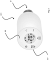
- Fig. 2 shows a design of a heating valve HV1.
- This is located in the example next to the actuator S1 for setting a valve position value for Control of a volume flow of a heating medium to or from the first consumer V1 has a detection device EV for the actual value of the room temperature.
- control and feedback electronics RE are arranged in the heating valve HV1, which is connected to the control unit 40a-k and receives control signals from this for adjusting the actuator S1.
- This actuator S1 acts on an actuating pin of the heating valve HV1, via which the opening and closing width of the heating valve HV1 is set and thus the volume flow of the heating medium is controlled.
- the control and feedback electronics RE is able to return the currently set valve position value to the control unit 40a-k, where it is then used for further adjustment.
- the actuator S1 is in the embodiment according to Fig. 2 designed as a stepper motor which has a step resolution of between 0 and 1000 steps, in particular between 0 and 600 or 0 and 300 steps.
- the amount of heating medium made available to the consumer V1 can be adjusted by operating the actuator S1. Due to the continuous feedback between the heating valve HV1 and the control unit 40a-k, a permanent hydraulic adjustment can be carried out in the respective consumer V1 and, through higher-level recording and processing of the respective valve position values, an adaptive hydraulic adjustment can be carried out in an entire heating system, so that the actuators S1 are always optimally controlled and operated.
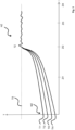
- Fig. 3 shows an example of the coordination of several heating valves HV1 to achieve a target temperature TS.
- the required target temperature TS is 22°C in the example.
- the detection devices EV provided in the individual rooms have determined different ACTUAL temperatures TI 1, TI 2, TI 3, TI 4 in the rooms at the first measurement time MZ.
- the control unit 40a-k now compares the valve position values of the heating valve HV 1 in the individual Rooms in such a way that the TARGET temperature TS is reached in all rooms at the same time by a target time TZ.
- a larger valve opening is set than in the room with the ACTUAL temperature TI 1 at the first measurement time MZ, which is already close to the TARGET temperature TS.
- automatic control can be carried out such that the amount of heat made available is distributed among the rooms in such a way that they have the same TARGET temperature TS at a target time TZ.
- the orientation of the rooms, their use and size, as well as the dimensioning of the radiators in the respective rooms are also taken into account here.
- the valve position values of the heating valve HV in the individual rooms are stored in the control unit 40a-k and continuously compared with the recorded room temperatures. If necessary, the valve position values can be adjusted and thus the volume flow in the heating valve HV1 to the respective consumers V1 can be adjusted and controlled.
- the heating system 10 according to the invention also makes it possible to maintain the temperature once reached in the rooms over a maintenance period HZ by continuously recording the temperature and, if necessary, readjusting the valve position values.
- the recording device EV records the ACTUAL temperature of the room continuously or in defined time intervals ZI 1 - ZI 4 of, for example, 1, 5 and 10 minutes, preferably between 1 and 10 or 15 minutes or in time intervals that can be set by the user.
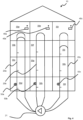
- FIG. 4 A special application of a heating system 10 in a building with several apartments 30a-l, which is not part of the invention, is Fig. 4 While in conventional systems with several heating lines 20a, b, c each heating line 20a, b, c is assigned its own circulation pump 21, Fig. 4 the special case in which three heating lines 20a, b, c of different lengths are provided, which have a common pump 21.
- digital line regulating valves 50a, b, c are provided in the heating lines 20a, b, c, which also communicate with control units 40a, b, c and are controlled by them. receive control signals.
- the heating system 10 or the control unit 40a, b, c assigned to it first simulates a heating system 10 with equally long lines (shown as dashed lines) and automatically carries out an adjustment via the control of the digital line regulating valves 50a, b, c. This achieves an even pressure distribution throughout the system and a corresponding load on the consumers (not shown) in the individual apartments 30a-l.
- the room temperature is then set using the method or heating system 10 described above. This involves coordination between the control units 40a, b, c, the respective consumers (not shown) and the line regulating valves 50a, b, c and the pump 21, and to create uniform conditions throughout the heating system 10.
- the control or adjustment between the individual units or apartments 30a-l then takes place in the manner described above.
Landscapes
- Engineering & Computer Science (AREA)
- Physics & Mathematics (AREA)
- Theoretical Computer Science (AREA)
- General Engineering & Computer Science (AREA)
- General Physics & Mathematics (AREA)
- Computing Systems (AREA)
- Life Sciences & Earth Sciences (AREA)
- Computational Linguistics (AREA)
- Data Mining & Analysis (AREA)
- Evolutionary Computation (AREA)
- General Health & Medical Sciences (AREA)
- Molecular Biology (AREA)
- Biomedical Technology (AREA)
- Artificial Intelligence (AREA)
- Biophysics (AREA)
- Mathematical Physics (AREA)
- Software Systems (AREA)
- Health & Medical Sciences (AREA)
- Mechanical Engineering (AREA)
- Thermal Sciences (AREA)
- Chemical & Material Sciences (AREA)
- Combustion & Propulsion (AREA)
- Automation & Control Theory (AREA)
- Steam Or Hot-Water Central Heating Systems (AREA)
Claims (14)
- Système de chauffage (10) a équilibrage hydraulique adaptatif automatique :• au moins une source de chauffage central, par exemple un brûleur (11)• au moins un premier consommateur (V1), chacun disposant d'une branche locale d'approvisionnement (3) et d'une branche locale de retour (4),• au moins une pompe à chaleur ou à circulation centrale (21a, b, c) pour transporter un fluide chauffant de la source de chaleur (11) au premier consommateur via une conduite d'alimentation centrale (3), le fluide chauffant pouvant retourner du premier consommateur (V1) à la source de chaleur via une conduite de retour centrale (4),• une première vanne de chauffage (HV1), en particulier une vanne thermostatique, affectée au premier consommateur (V1) et disposée dans la branche d'écoulement respective (3),• un premier actionneur (S1) associé à la première vanne de chauffage (HV1) et équipé d'une première électronique de commande et de rétroaction (RE) pour régler une valeur de position de la vanne afin de contrôler un débit volumétrique du fluide chauffant dans le premier consommateur (V1), l'actionneur (S1) agissant de préférence sur un axe d'actionnement de la vanne de chauffage (HV1),• un dispositif de détection (EV) de la valeur réelle de la température ambiante (TI1-4),• une unité de commande (40a-l) couplée au dispositif de détection (EV) et au premier actionneur (S1),dans lequel une valeur de consigne pour la température ambiante (TS) peut être stockée dans l'unité de commande (40a-l) et un signal de commande pour la valeur de position de la vanne peut être émis vers l'électronique de commande et de retour (RE) via l'unité de commande (40a-l) et la valeur de consigne pour la température ambiante (TS) peut être réglée par l'actionnement incrémental de l'actionneur (S1) et, lorsque la valeur de consigne pour la température ambiante (TS) est atteinte, la valeur de position de la vanne réglée respective peut être transmise à l'unité de commande (40a-l) via l'électronique de commande et de retour (RE), la valeur de consigne de la température ambiante (TS) peut être réglée et la valeur de position de vanne réglée respective peut être renvoyée à l'unité de commande (40a-l) via l'électronique de commande et de rétroaction (RE) lorsque la valeur de consigne de la température ambiante (TS) est atteinte et l'équilibrage hydraulique adaptatif peut être réalisé par un réglage commandé dans le temps, en particulier continu, de la valeur de position de vanne au moyen de l'unité de commande (40a-l), en particulier un réglage continu de la valeur de position de vanne, caractérisé par le fait que intègre le système de chauffage dans un réseau de distribution comprenant plusieurs sections, les sections ayant des lignes de chauffage indépendantes (20a, b, c) chacune avec au moins un consommateur (V1), les lignes de chauffage alimentent chacune un certain nombre d'appartements (30a-l) et le réseau de distribution a au moins une unité de contrôle de réseau (NE) pour l'équilibrage hydraulique dynamique dans l'ensemble du réseau de distribution, dans lequel l'unité de contrôle de réseau (NE) contrôle le système de chauffage directement via les unités de contrôle (40a-l) ou via les unités de contrôle centrales.
- Système de chauffage (10) selon la revendication 1, caractérisé par le fait qu'au moins un deuxième consommateur est prévu et que l'unité de commande (40a-l) pour le réglage de la valeur de consigne de la température ambiante (TS) émet des signaux de commande pour le réglage de la valeur de position de vanne respective à l'électronique de commande et de rétroaction (RE) des consommateurs respectifs (V1) et, dans l'unité de commande (40a-l), après égalisation des valeurs de position des vannes du premier et du deuxième consommateur (V1), une sortie des valeurs individuelles de position des vannes vers l'électronique de commande et de retour (RE) du premier et du deuxième consommateur (V1) est fournie pour le réglage de la température ambiante et les consommateurs (V1), en particulier dans l'électronique de commande et de retour (RE) du premier et du deuxième consommateur (V1), sont fournis pour le réglage de la température ambiante. Les consommateurs (V1) sont disposés en particulier dans des pièces séparées et un couplage est prévu directement avec une unité de commande centrale ou par l'intermédiaire d'une unité de commande (40a-l) respectivement affectée aux consommateurs et dans laquelle dans l'unité de commande du réseau (NE), les unités de commande centrales ou les unités de commande (40a-l), un comportement thermique temporel peut de préférence être mémorisé, un comportement thermique temporel peut de préférence être stocké via des profils de valeurs de consigne récupérables pour la température ambiante et l'équilibrage hydraulique adaptatif peut être effectué en fonction des profils de valeurs de consigne pour la température ambiante et une adaptation du comportement thermique temporel est prévue en fonction de l'heure de la journée, de l'utilisation de la pièce, de la température extérieure, des courbes de température saisonnières, de l'orientation de la pièce et/ou de la conception.
- Système de chauffage (10) selon l'une des revendications précédentes, caractérisé en ce que l'actionneur (S1) est conçu comme un moteur pas à pas qui a une résolution de pas comprise entre 0 et 1000 pas, en particulier entre 0 et 800 pas, de préférence entre 0 et 600 pas, de préférence encore entre 0 et 300 pas, dans lequel la vanne de chauffage (HV1) est conçue en particulier comme une vanne à moteur pas à pas et l'actionneur (S1) est fourni en tant que partie de la vanne à moteur pas à pas.
- Système de chauffage (10) selon l'une des revendications précédentes, caractérisé par le fait qu'en plus des profils de valeurs de consigne pour la température ambiante, une rampe de température de consigne est prévue et une vitesse d'actionnement de l'actionneur (S1) est prévue en fonction de la rampe de température de consigne et/ou le dispositif de détection (EV) est de préférence conçu comme un dispositif de mesure de la température indépendant ou comme un dispositif de mesure de la température intégré dans la vanne de chauffage (HV1) ou dans un thermostat d'ambiance.
- Système de chauffage (10) selon l'une des revendications précédentes, caractérisé par le fait que l'unité de commande du réseau (NE), l'unité de commande (40a-l) et/ou l'unité de commande centrale sont disposées de manière décentralisée et sont intégrées dans un réseau de données ou que l'unité de commande du réseau (NE), l'unité de commande (40a-l) et/ou l'unité de commande centrale sont conçues pour être opérationnelles sur un serveur (50) ou un serveur virtuel et sont transmises via l'unité de commande du réseau (NE) respective, l'unité de commande (40a-l) et/ou l'unité de commande centrale, l'unité de commande (40a-l) et/ou l'unité de commande centrale sont conçues pour fonctionner sur un serveur (50) ou un serveur virtuel et un signal de commande pour la source de chauffage et/ou la pompe de circulation ou de chaleur (21a, b, c) peut être émis selon les besoins via l'unité de commande du réseau (NE), l'unité de commande (40a-l) ou l'unité de commande centrale afin d'augmenter ou de réduire la puissance d'un chauffage ou d'une pompe respectif.
- Procédé de réalisation d'un équilibrage hydraulique automatique et adaptatif dans un système de chauffage (10) selon l'une des revendications 1 à 5, comprenant les étapes suivantes :a. Détection d'une valeur réelle actuelle de la température ambiante (TI 1-4) et transmission de la valeur réelle de la température ambiante (TI 1-4) à une unité de commande (40a-l),b. Comparaison de la valeur réelle de la température ambiante (TI 1-4) avec une valeur de consigne de la température ambiante (TS) enregistrée dans l'unité de commande (40a-l),c. Dérivation d'une valeur de position de la vanne à partir de l'écart entre la valeur de consigne de la température ambiante (TS) et la valeur réelle de la température ambiante (TI 1-4),d. Sortie d'un signal de commande vers une électronique de commande et de rétroaction (RE) affectée à une vanne de chauffage (HV1),e. Actionnement d'un actionneur (S1) de la vanne de chauffage (HV1) par l'électronique de commande et de rétroaction (RE) pour régler la valeur de la position de la vanne sur la vanne de chauffage (HV1),f. Retour de la valeur de la position de la vanne à l'unité de contrôle (40aI),g. Répéter les étapes a.) à f.) jusqu'à ce que la valeur de consigne de la température ambiante (TS) soit atteinte,dans lequel, en particulier, la valeur de consigne de la température ambiante (TS) représente un comportement thermique dans le temps, notamment en fonction de l'heure de la journée, de l'utilisation de la pièce, de la température extérieure, des courbes de température saisonnières, de l'orientation et/ou de la conception de la pièce, et/ou le réglage s'effectue en continu ou à des intervalles de temps définis (ZI1-4) et/ou, de préférence, plusieurs vannes de chauffage interconnectées (HV1) sont prévues, et l'unité de commande (HV2) commande les actionneurs (S1) des vannes de chauffage respectives (HV1) de manière à ce que la valeur de consigne de la température ambiante (TS) soit atteinte par un ajustement individuel des valeurs de position des vannes de chauffage respectives (HV1), dans lequel une ouverture et/ou une fermeture indépendante des vannes de chauffage respectives (HV1) est effectuée et/ou le système de commande prend en compte différents incidents de charge survenant aux vannes de chauffage (HV1) au cours de l'équilibrage, caractérisé en ce qu'un équilibrage hydraulique adaptatif est effectué dans un système de chauffage de bâtiment équipé d'un réseau de distribution comprenant plusieurs sections, dans lequel les sections ont des lignes de chauffage indépendantes (20a, b, c) chacune avec au moins un consommateur (V1) et les lignes de chauffage alimentent chacune un certain nombre d'appartements (30a-l) et dans lequel les étapes a.) à f.) sont chacune effectuées dans des sections individuelles d'un réseau de distribution et l'équilibrage pour l'ensemble du réseau est effectué par une unité de contrôle du réseau (NE), dans laquelle le réseau de distribution comporte en particulier plusieurs unités de contrôle (40a-l) ou des unités de contrôle centrales de niveau supérieur et un couplage de données de l'unité de contrôle du réseau (NE) avec plusieurs unités de contrôle (40a-l) et/ou des unités de contrôle centrales est prévu et dans laquelle le réseau de distribution ou les sections comportent plusieurs lignes de chauffage (20a, b, c) alimentées en particulier par une source de chauffage central, et l'au moins une unité de contrôle du réseau (NE) et une pluralité d'unités de contrôle (40a-l) ou d'unités de contrôle central effectuent l'équilibrage à travers les lignes de chauffage (20a, b, c) et l'unité de contrôle du réseau (NE) émet les signaux de contrôle soit directement, soit par l'intermédiaire des unités de contrôle (40a-l) et/ou des unités de contrôle centrales, à l'électronique de contrôle et de rétroaction (RE) des vannes de chauffage (HV1), dans laquelle l'unité de contrôle du réseau (NE), les unités de contrôle (40a-l) ou les unités de contrôle centrales afin d'atteindre les valeurs de consigne pour la température ambiante (TS) et, en fonction de la charge requise dans chaque cas, émet un signal de contrôle pour la source de chauffage et/ou la (les) pompe(s) de circulation ou de chaleur (21a, b, c) selon les besoins afin d'augmenter ou de réduire la puissance du chauffage et/ou de la pompe.
- Procédé selon la revendication 6, caractérisé par le fait que les rampes de température permettant d'atteindre les valeurs de consigne de la température ambiante (TS) sont enregistrées dans l'unité de commande (40a-l) et que les actionneurs (S1) sont commandés en fonction des rampes de température et/ou que l'actionneur (S1) est actionné par étapes avec une résolution de pas comprise entre 0 et 1000 pas, en particulier entre 0 et 800 pas, de préférence entre 0 et 600 pas, de manière particulièrement préférée entre 0 et 300 pas.
- Procédé selon l'une des revendications 6 ou 7, caractérisé par le fait que les signaux de commande sont transmis sans fil, en particulier via une connexion W-LAN, la radio, Bluetooth ou un réseau téléphonique ou mobile et/ou l'unité de commande du réseau (NE), les unités de commande (40a-l) et/ou les unités de commande centrales sont fournies de manière décentralisée ou sont intégrées dans un réseau de données ou l'unité de commande du réseau (NE), l'unité de commande (40a-l) et/ou l'unité de commande centrale sont exploitées sur un serveur (50) ou un serveur virtuel, de sorte que la commande simultanée de plusieurs systèmes de chauffage (11) et/ou réseaux de distribution s'effectue par l'intermédiaire d'un serveur (50) du réseau.
- Procédé mis en oeuvre par ordinateur pour l'entraînement d'un réseau neuronal artificiel (RNA) pour l'exécution d'un réglage hydraulique adaptatif selon l'une quelconque des revendications 6 à 8 dans un système de chauffage selon l'une quelconque des revendications 1 à 5, qui prédit au moins une valeur de position de vanne pour atteindre une valeur de consigne d'une température ambiante (TS) dans un système de chauffage (10), dans lequel une intégration du système de chauffage dans un réseau de distribution comprenant une pluralité de sections est prévue et les sections comprennent des lignes de chauffage indépendantes (20a, b, c) ayant chacune au moins un consommateur (V1) et les lignes de chauffage alimentant chacune un certain nombre d'appartements (30a-l), le comportement de l'RNA étant caractérisé par un ensemble de paramètres, avec les étapes suivantes• un ensemble d'ensembles de données d'apprentissage est fourni, dans lequel chaque ensemble de données d'apprentissage pour une valeur de position de vanne comprend un ensemble de paramètres caractérisant la réalisation d'une valeur de consigne d'une température ambiante (TS), au moins une mesure pour l'actionnement incrémentiel de l'actionneur (S1), qui est nécessaire pour atteindre une valeur d'ouverture de la vanne de chauffage (HV1) ;• Pour chaque ensemble de données d'apprentissage, l'ensemble de paramètres qu'il contient et la mesure de l'actionnement incrémental de l'actionneur (S1) qu'il contient sont transmis à l'RNA en tant qu'entrées afin d'obtenir une prédiction et/ou une classification pour au moins une valeur d'ouverture de la vanne de chauffage (HV1) en tant que sortie ;• la prédiction et/ou la classification de la valeur d'ouverture de la vanne de chauffage (HV1) est comparée à la valeur de la valeur d'ouverture de la vanne de chauffage (HV1) contenue dans l'ensemble de données d'apprentissage ;• Un actionnement incrémental de l'actionneur (S1) est évalué, qui dépend d'un écart déterminé dans la comparaison ;
les paramètres et/ou les ensembles de données d'apprentissage de l'RNA sont adaptés à l'objectif d'optimisation consistant à améliorer la valeur de l'actionnement incrémentiel de l'actionneur (S1) et par conséquent l'ensemble de données d'apprentissage contient en outre, à titre facultatif, les éléments suivants• une identification du lieu d'installation de la vanne de chauffage (HV1) dans le système de chauffage (10) et/ou• une identification de la position du consommateur (V1) dans une ligne de chauffage (20a, b, c) et/ou• une mesure de la température ambiante au moment du réglage de la valeur d'ouverture de la vanne de chauffage (HV1), et/ou• une information sur la façon dont le système de chauffage (10) est construit, et/ou• une information sur le comportement de la charge dans le système de chauffage (10) et/ou• au moins des extraits de données de planification pour les lignes de chauffage (20a, b, c) ou le bâtiment (100) à chauffer, un nombre d'appartements (30a-l) ou le local à chauffer, et/ou• une information sur les vannes de chauffage (HV1) présentes dans le système de chauffage (10) et couplées les unes aux autres, et/ou• une information sur la proportion d'une quantité totale de chaleur ou d'une pression dans le système de chauffage (10) qui est disponible à la vanne de chauffage respective (HV1) et/ou• une information sur la puissance maximale que peut fournir le générateur de chaleur affecté au système de chauffage (10), en particulier le brûleur (11) ou la pompe de circulation ou de chaleur (21a, b, c) affectée au système de chauffage (10), en tant qu'autres données à fournir au CN. - Réseau de neurones artificiels, RNA, entraîné avec la méthode selon la revendication 9.
- Ensemble de données de paramètres caractérisant un RNA obtenu par la méthode selon la revendication 9.
- Méthode mise en oeuvre par ordinateur pour prédire et/ou classer la valeur de réglage d'une vanne de chauffage (HV1) dans un système de chauffage (10) selon l'une des revendications 1 à 5, dans laquelle l'intégration du système de chauffage dans un réseau de distribution ayant une pluralité de sections est prévue avec les sections ayant des lignes de chauffage indépendantes (20a, b, c) ayant chacune au moins un consommateur (V1), avec les lignes de chauffage (20a, b, c) alimentant chacune un certain nombre d'appartements (30a-l), avec les étapes suivantes :• Un ensemble de paramètres caractérisant la valeur SET requise de la température ambiante (TS) est déterminé ;• au moins une mesure de la valeur de commande de chaque vanne de chauffage (HV1) dans le système de chauffage (10) est déterminée ;• les paramètres et la mesure de la valeur d'actionnement d'une vanne de chauffage respective (HV1) dans le système de chauffage (10) sont transmis à un RNA entraîné en tant qu'entrées ;au moins une prédiction et/ou une classification pour une mesure de la valeur de réglage de la vanne pour atteindre la valeur de consigne de la température ambiante (TS) dans le système de chauffage (10) ou la ligne de chauffage (20a, b, c) est récupérée en tant que sortie de l'RNA, dans laquelle l'RNA est éventuellement fourni avec les informations suivantes :• une identification de l'endroit où au moins une vanne de chauffage (HV1) a été installée, et/ou• une mesure de la température ambiante ou de la valeur réelle de la température ambiante (TI1-4) sur le lieu d'installation de la vanne de chauffage (HV1) est fournie en entrée et/ou, de préférence, en réponse au fait que la valeur de consigne de la température ambiante (TS) n'est pas atteinte avec une valeur de réglage de la vanne d'une première vanne de chauffage (HV1) prédite pour un premier lieu d'installation, une autre prédiction et/ou classification pour une valeur de position de la vanne d'une deuxième vanne de chauffage (HV1), qui est fournie sur un deuxième lieu d'installation, est récupérée en tant que sortie d'un RNA entraîné.
- Un ou plusieurs programmes d'ordinateur comprenant des instructions lisibles par machine qui, lorsqu'elles sont exécutées sur un ou plusieurs ordinateurs et/ou sur une ou plusieurs unités de contrôle (40a-l) et/ou sur un ou plusieurs serveurs (50), amènent le ou les ordinateurs et/ou la ou les unités de contrôle (40a-l) et/ou le ou les serveurs (50) à exécuter une méthode selon la revendication 12.
- Support de données lisible par machine et/ou produit de téléchargement comprenant un ou plusieurs programmes informatiques selon la revendication 13.
Applications Claiming Priority (2)
| Application Number | Priority Date | Filing Date | Title |
|---|---|---|---|
| DE102020117945 | 2020-07-07 | ||
| DE102020120043.9A DE102020120043A1 (de) | 2020-07-07 | 2020-07-29 | Heizungssystem mit automatischem adaptivem hydraulischem Abgleich |
Publications (3)
| Publication Number | Publication Date |
|---|---|
| EP3936770A1 EP3936770A1 (fr) | 2022-01-12 |
| EP3936770C0 EP3936770C0 (fr) | 2024-11-27 |
| EP3936770B1 true EP3936770B1 (fr) | 2024-11-27 |
Family
ID=77316806
Family Applications (1)
| Application Number | Title | Priority Date | Filing Date |
|---|---|---|---|
| EP21020410.3A Active EP3936770B1 (fr) | 2020-07-07 | 2021-08-11 | Système de chauffage à équilibrage hydraulique adaptatif automatique |
Country Status (1)
| Country | Link |
|---|---|
| EP (1) | EP3936770B1 (fr) |
Families Citing this family (8)
| Publication number | Priority date | Publication date | Assignee | Title |
|---|---|---|---|---|
| DE102022101313A1 (de) * | 2022-01-20 | 2023-07-20 | Vaillant Gmbh | Verfahren zur Konfiguration eines Klimasystems, Computerprogramm, Regel- und Steuerge-rät, Klimagerät und Verwendung von Daten |
| CN114704873A (zh) * | 2022-01-25 | 2022-07-05 | 河海大学 | 一种建筑适应性供暖方法 |
| CN114704874B (zh) * | 2022-03-25 | 2023-12-19 | 内蒙古思铂睿特节能科技有限公司 | 一种基于柔性供热系统的热力站供热参数的精准控制方法 |
| DE102022001628A1 (de) * | 2022-05-10 | 2023-11-16 | KSB SE & Co. KGaA | Verfahren zur Überwachung und/oder Steuerung einer Heizungsanlage |
| DE102022001630A1 (de) * | 2022-05-10 | 2023-11-16 | KSB SE & Co. KGaA | Verfahren zur Steuerung und/oder Regelung einer Heizungsanlage zum Beheizen wenigstens eines Raumes sowie Heizungsanlage |
| EP4556800A1 (fr) | 2023-11-20 | 2025-05-21 | BDR Thermea Group B.V. | Mode d'équilibrage hydronique dans un système de chauffage multi-source |
| CN117968143B (zh) * | 2024-04-01 | 2024-06-04 | 陕西德联新能源有限公司 | 一种供热系统的节能优化方法及系统 |
| CN119289760B (zh) * | 2024-09-12 | 2025-11-21 | 中国船舶集团有限公司第七○八研究所 | 一种船舶区域海水冷却系统流量平衡控制方法 |
Family Cites Families (5)
| Publication number | Priority date | Publication date | Assignee | Title |
|---|---|---|---|---|
| DE102006060324A1 (de) * | 2006-12-20 | 2008-07-03 | Techem Energy Services Gmbh | Verfahren und System zur Detektion des hydraulischen Abgleichs einer Heizungsanlage |
| DE102011018698A1 (de) * | 2011-04-26 | 2012-10-31 | Rwe Effizienz Gmbh | Verfahren und System zum automatischen hydraulischen Abgleichen von Heizkörpern |
| DE102012018778B4 (de) * | 2012-09-24 | 2015-02-05 | Huu-Thoi Le | Verfahren zum Betrieb einer Heizungsanlage, Verfahren zum Betrieb einer Kühlanlage sowie Regeleinheit |
| CA2946117A1 (fr) * | 2016-10-21 | 2018-04-21 | John Faiczak | Methode, appareil et systeme d'equilibrage de la pression de fluide des systemes de distribution de fluide |
| CN111811016B (zh) * | 2020-07-20 | 2021-10-29 | 瑞纳智能设备股份有限公司 | 一种供暖机组单元间水力平衡调节方法及系统 |
-
2021
- 2021-08-11 EP EP21020410.3A patent/EP3936770B1/fr active Active
Also Published As
| Publication number | Publication date |
|---|---|
| EP3936770C0 (fr) | 2024-11-27 |
| EP3936770A1 (fr) | 2022-01-12 |
Similar Documents
| Publication | Publication Date | Title |
|---|---|---|
| EP3936770B1 (fr) | Système de chauffage à équilibrage hydraulique adaptatif automatique | |
| EP3665542B1 (fr) | Dispositif de réglage autorégulé pour une vanne de régulation de fluide, système de thermorégulation et un système de distribution comprenant celui-ci, ainsi que procédé associé | |
| EP3602229B1 (fr) | Procédé et dispositif d'optimisation, basée sur internet, de paramètres d'une régulation de chauffage | |
| EP3593055B1 (fr) | Procédé pour faire fonctionner une installation de chauffage | |
| EP3179173B1 (fr) | Procédé et système d'équilibrage hydraulique automatique de consommateurs dans une installation de chauffage ou de réfrigération | |
| DE102007030492B4 (de) | Gebäudemodellbasiertes prädiktives Verfahren zur Generierung und Weitergabe von Informationen über Auswirkungen von Sollwert-Änderungen | |
| EP0729086B1 (fr) | Procédé et dispositif pour réguler un système de chauffage par température basse | |
| EP1645928B1 (fr) | Procédé de détermination de l'état d'alimentation d'une surface chauffante et régulateur d'état d'alimentation | |
| EP2896895B1 (fr) | Procédé de réglage adaptatif d'un système de chauffage | |
| DE102008057730A1 (de) | Verfahren zum Betreiben eines Systems zum Transport thermischer Energie über ein flüssiges Medium | |
| EP4522924A1 (fr) | Procédé de commande en boucle ouverte et/ou boucle fermée d'un système de chauffage pour chauffer au moins un espace et système de chauffage | |
| DE102020120043A1 (de) | Heizungssystem mit automatischem adaptivem hydraulischem Abgleich | |
| EP3473939B1 (fr) | Procédé de fonctionnement d'une installation de chauffage et installation de chauffage | |
| EP3739267B1 (fr) | Procédé et unité de réglage d'un circuit de chauffage | |
| EP3647899A1 (fr) | Procédé de fonctionnement d'une soupape, unité de commande électronique associée et entraînement de soupape | |
| EP4071414B1 (fr) | Procédé, système et programme informatique de commande d'un générateur de chaleur | |
| EP3168540A1 (fr) | Procédé d'exécution d'un équilibrage hydraulique automatisé, soupape et installation de chauffage associées | |
| WO2003023288A1 (fr) | Installation de chauffage central | |
| EP4015918B1 (fr) | Procédé et dispositif de commande d'un circuit primaire d'une installation de chauffage | |
| DE102010055080A1 (de) | Verfahren zur Optimierung der Vorlaufsolltemperatur eines Heizfluids und Heizsystem zur Beheizung von zumindest zwei separaten Räumen | |
| DE102015113340A1 (de) | Heizungsanlage und Verfahren zum Betreiben einer Heizungsanlage | |
| DE102023103643A1 (de) | Vorrichtung für ein Heizsystem sowie Heizsystem und Verfahren zu dessen Betrieb | |
| EP1837729A2 (fr) | Procédé et dispositif destinés à la mise à disposition de la chaleur selon les besoins dans une installation de chauffage | |
| DE102010047913A1 (de) | Intelligenter Heizkreisverteiler und Verfahren zum Betrieb desselben | |
| DE9415749U1 (de) | Einrichtung zur Regelung von Heiz- und Kesselkreisen einer Heizungsanlage |
Legal Events
| Date | Code | Title | Description |
|---|---|---|---|
| PUAI | Public reference made under article 153(3) epc to a published international application that has entered the european phase |
Free format text: ORIGINAL CODE: 0009012 |
|
| STAA | Information on the status of an ep patent application or granted ep patent |
Free format text: STATUS: THE APPLICATION HAS BEEN PUBLISHED |
|
| AK | Designated contracting states |
Kind code of ref document: A1 Designated state(s): AL AT BE BG CH CY CZ DE DK EE ES FI FR GB GR HR HU IE IS IT LI LT LU LV MC MK MT NL NO PL PT RO RS SE SI SK SM TR |
|
| B565 | Issuance of search results under rule 164(2) epc |
Effective date: 20211202 |
|
| RIN1 | Information on inventor provided before grant (corrected) |
Inventor name: SUIC, ORHAN |
|
| STAA | Information on the status of an ep patent application or granted ep patent |
Free format text: STATUS: REQUEST FOR EXAMINATION WAS MADE |
|
| 17P | Request for examination filed |
Effective date: 20220629 |
|
| RBV | Designated contracting states (corrected) |
Designated state(s): AL AT BE BG CH CY CZ DE DK EE ES FI FR GB GR HR HU IE IS IT LI LT LU LV MC MK MT NL NO PL PT RO RS SE SI SK SM TR |
|
| STAA | Information on the status of an ep patent application or granted ep patent |
Free format text: STATUS: EXAMINATION IS IN PROGRESS |
|
| 17Q | First examination report despatched |
Effective date: 20240304 |
|
| RAP1 | Party data changed (applicant data changed or rights of an application transferred) |
Owner name: BLOSSOM-IC INTELLIGENT CONTROLS AG |
|
| RIC1 | Information provided on ipc code assigned before grant |
Ipc: G05D 23/19 20060101ALI20240603BHEP Ipc: G06N 3/08 20060101ALI20240603BHEP Ipc: G05B 13/02 20060101ALI20240603BHEP Ipc: F24D 19/10 20060101AFI20240603BHEP |
|
| GRAJ | Information related to disapproval of communication of intention to grant by the applicant or resumption of examination proceedings by the epo deleted |
Free format text: ORIGINAL CODE: EPIDOSDIGR1 |
|
| GRAP | Despatch of communication of intention to grant a patent |
Free format text: ORIGINAL CODE: EPIDOSNIGR1 |
|
| GRAP | Despatch of communication of intention to grant a patent |
Free format text: ORIGINAL CODE: EPIDOSNIGR1 |
|
| STAA | Information on the status of an ep patent application or granted ep patent |
Free format text: STATUS: GRANT OF PATENT IS INTENDED |
|
| INTG | Intention to grant announced |
Effective date: 20240725 |
|
| GRAS | Grant fee paid |
Free format text: ORIGINAL CODE: EPIDOSNIGR3 |
|
| GRAA | (expected) grant |
Free format text: ORIGINAL CODE: 0009210 |
|
| STAA | Information on the status of an ep patent application or granted ep patent |
Free format text: STATUS: THE PATENT HAS BEEN GRANTED |
|
| AK | Designated contracting states |
Kind code of ref document: B1 Designated state(s): AL AT BE BG CH CY CZ DE DK EE ES FI FR GB GR HR HU IE IS IT LI LT LU LV MC MK MT NL NO PL PT RO RS SE SI SK SM TR |
|
| REG | Reference to a national code |
Ref country code: GB Ref legal event code: FG4D Free format text: NOT ENGLISH |
|
| REG | Reference to a national code |
Ref country code: CH Ref legal event code: EP |
|
| REG | Reference to a national code |
Ref country code: IE Ref legal event code: FG4D Free format text: LANGUAGE OF EP DOCUMENT: GERMAN |
|
| REG | Reference to a national code |
Ref country code: DE Ref legal event code: R096 Ref document number: 502021005913 Country of ref document: DE |
|
| U01 | Request for unitary effect filed |
Effective date: 20241222 |
|
| U07 | Unitary effect registered |
Designated state(s): AT BE BG DE DK EE FI FR IT LT LU LV MT NL PT RO SE SI Effective date: 20250114 |
|
| PG25 | Lapsed in a contracting state [announced via postgrant information from national office to epo] |
Ref country code: IS Free format text: LAPSE BECAUSE OF FAILURE TO SUBMIT A TRANSLATION OF THE DESCRIPTION OR TO PAY THE FEE WITHIN THE PRESCRIBED TIME-LIMIT Effective date: 20250327 Ref country code: HR Free format text: LAPSE BECAUSE OF FAILURE TO SUBMIT A TRANSLATION OF THE DESCRIPTION OR TO PAY THE FEE WITHIN THE PRESCRIBED TIME-LIMIT Effective date: 20241127 |
|
| PG25 | Lapsed in a contracting state [announced via postgrant information from national office to epo] |
Ref country code: ES Free format text: LAPSE BECAUSE OF FAILURE TO SUBMIT A TRANSLATION OF THE DESCRIPTION OR TO PAY THE FEE WITHIN THE PRESCRIBED TIME-LIMIT Effective date: 20241127 |
|
| PG25 | Lapsed in a contracting state [announced via postgrant information from national office to epo] |
Ref country code: NO Free format text: LAPSE BECAUSE OF FAILURE TO SUBMIT A TRANSLATION OF THE DESCRIPTION OR TO PAY THE FEE WITHIN THE PRESCRIBED TIME-LIMIT Effective date: 20250227 |
|
| PG25 | Lapsed in a contracting state [announced via postgrant information from national office to epo] |
Ref country code: GR Free format text: LAPSE BECAUSE OF FAILURE TO SUBMIT A TRANSLATION OF THE DESCRIPTION OR TO PAY THE FEE WITHIN THE PRESCRIBED TIME-LIMIT Effective date: 20250228 |
|
| PG25 | Lapsed in a contracting state [announced via postgrant information from national office to epo] |
Ref country code: PL Free format text: LAPSE BECAUSE OF FAILURE TO SUBMIT A TRANSLATION OF THE DESCRIPTION OR TO PAY THE FEE WITHIN THE PRESCRIBED TIME-LIMIT Effective date: 20241127 |
|
| PG25 | Lapsed in a contracting state [announced via postgrant information from national office to epo] |
Ref country code: RS Free format text: LAPSE BECAUSE OF FAILURE TO SUBMIT A TRANSLATION OF THE DESCRIPTION OR TO PAY THE FEE WITHIN THE PRESCRIBED TIME-LIMIT Effective date: 20250227 |
|
| PG25 | Lapsed in a contracting state [announced via postgrant information from national office to epo] |
Ref country code: SM Free format text: LAPSE BECAUSE OF FAILURE TO SUBMIT A TRANSLATION OF THE DESCRIPTION OR TO PAY THE FEE WITHIN THE PRESCRIBED TIME-LIMIT Effective date: 20241127 |
|
| PG25 | Lapsed in a contracting state [announced via postgrant information from national office to epo] |
Ref country code: SK Free format text: LAPSE BECAUSE OF FAILURE TO SUBMIT A TRANSLATION OF THE DESCRIPTION OR TO PAY THE FEE WITHIN THE PRESCRIBED TIME-LIMIT Effective date: 20241127 |
|
| PG25 | Lapsed in a contracting state [announced via postgrant information from national office to epo] |
Ref country code: CZ Free format text: LAPSE BECAUSE OF FAILURE TO SUBMIT A TRANSLATION OF THE DESCRIPTION OR TO PAY THE FEE WITHIN THE PRESCRIBED TIME-LIMIT Effective date: 20241127 |
|
| U20 | Renewal fee for the european patent with unitary effect paid |
Year of fee payment: 5 Effective date: 20250826 |
|
| PLBE | No opposition filed within time limit |
Free format text: ORIGINAL CODE: 0009261 |
|
| STAA | Information on the status of an ep patent application or granted ep patent |
Free format text: STATUS: NO OPPOSITION FILED WITHIN TIME LIMIT |
|
| PGFP | Annual fee paid to national office [announced via postgrant information from national office to epo] |
Ref country code: TR Payment date: 20250808 Year of fee payment: 5 |
|
| PGFP | Annual fee paid to national office [announced via postgrant information from national office to epo] |
Ref country code: GB Payment date: 20250822 Year of fee payment: 5 |
|
| PGFP | Annual fee paid to national office [announced via postgrant information from national office to epo] |
Ref country code: CH Payment date: 20250901 Year of fee payment: 5 |
|
| 26N | No opposition filed |
Effective date: 20250828 |
|
| PG25 | Lapsed in a contracting state [announced via postgrant information from national office to epo] |
Ref country code: MC Free format text: LAPSE BECAUSE OF FAILURE TO SUBMIT A TRANSLATION OF THE DESCRIPTION OR TO PAY THE FEE WITHIN THE PRESCRIBED TIME-LIMIT Effective date: 20241127 |