EP3936829A1 - Induktiver positionssensor mit mindestens einer sendespule, einem absolutpositionempfangsspulenpaar, einem hochauflösenden positionsbestimmungsspulenpaar und einem leitfähigen geber - Google Patents
Induktiver positionssensor mit mindestens einer sendespule, einem absolutpositionempfangsspulenpaar, einem hochauflösenden positionsbestimmungsspulenpaar und einem leitfähigen geber Download PDFInfo
- Publication number
- EP3936829A1 EP3936829A1 EP21178772.6A EP21178772A EP3936829A1 EP 3936829 A1 EP3936829 A1 EP 3936829A1 EP 21178772 A EP21178772 A EP 21178772A EP 3936829 A1 EP3936829 A1 EP 3936829A1
- Authority
- EP
- European Patent Office
- Prior art keywords
- position sensor
- receive coil
- inductive position
- inductive
- coil pair
- Prior art date
- Legal status (The legal status is an assumption and is not a legal conclusion. Google has not performed a legal analysis and makes no representation as to the accuracy of the status listed.)
- Granted
Links
Images




Classifications
-
- G—PHYSICS
- G01—MEASURING; TESTING
- G01B—MEASURING LENGTH, THICKNESS OR SIMILAR LINEAR DIMENSIONS; MEASURING ANGLES; MEASURING AREAS; MEASURING IRREGULARITIES OF SURFACES OR CONTOURS
- G01B7/00—Measuring arrangements characterised by the use of electric or magnetic techniques
- G01B7/003—Measuring arrangements characterised by the use of electric or magnetic techniques for measuring position, not involving coordinate determination
-
- G—PHYSICS
- G01—MEASURING; TESTING
- G01D—MEASURING NOT SPECIALLY ADAPTED FOR A SPECIFIC VARIABLE; ARRANGEMENTS FOR MEASURING TWO OR MORE VARIABLES NOT COVERED IN A SINGLE OTHER SUBCLASS; TARIFF METERING APPARATUS; MEASURING OR TESTING NOT OTHERWISE PROVIDED FOR
- G01D5/00—Mechanical means for transferring the output of a sensing member; Means for converting the output of a sensing member to another variable where the form or nature of the sensing member does not constrain the means for converting; Transducers not specially adapted for a specific variable
- G01D5/12—Mechanical means for transferring the output of a sensing member; Means for converting the output of a sensing member to another variable where the form or nature of the sensing member does not constrain the means for converting; Transducers not specially adapted for a specific variable using electric or magnetic means
- G01D5/14—Mechanical means for transferring the output of a sensing member; Means for converting the output of a sensing member to another variable where the form or nature of the sensing member does not constrain the means for converting; Transducers not specially adapted for a specific variable using electric or magnetic means influencing the magnitude of a current or voltage
- G01D5/20—Mechanical means for transferring the output of a sensing member; Means for converting the output of a sensing member to another variable where the form or nature of the sensing member does not constrain the means for converting; Transducers not specially adapted for a specific variable using electric or magnetic means influencing the magnitude of a current or voltage by varying inductance, e.g. by a movable armature
-
- G—PHYSICS
- G01—MEASURING; TESTING
- G01D—MEASURING NOT SPECIALLY ADAPTED FOR A SPECIFIC VARIABLE; ARRANGEMENTS FOR MEASURING TWO OR MORE VARIABLES NOT COVERED IN A SINGLE OTHER SUBCLASS; TARIFF METERING APPARATUS; MEASURING OR TESTING NOT OTHERWISE PROVIDED FOR
- G01D5/00—Mechanical means for transferring the output of a sensing member; Means for converting the output of a sensing member to another variable where the form or nature of the sensing member does not constrain the means for converting; Transducers not specially adapted for a specific variable
- G01D5/12—Mechanical means for transferring the output of a sensing member; Means for converting the output of a sensing member to another variable where the form or nature of the sensing member does not constrain the means for converting; Transducers not specially adapted for a specific variable using electric or magnetic means
- G01D5/14—Mechanical means for transferring the output of a sensing member; Means for converting the output of a sensing member to another variable where the form or nature of the sensing member does not constrain the means for converting; Transducers not specially adapted for a specific variable using electric or magnetic means influencing the magnitude of a current or voltage
- G01D5/20—Mechanical means for transferring the output of a sensing member; Means for converting the output of a sensing member to another variable where the form or nature of the sensing member does not constrain the means for converting; Transducers not specially adapted for a specific variable using electric or magnetic means influencing the magnitude of a current or voltage by varying inductance, e.g. by a movable armature
- G01D5/204—Mechanical means for transferring the output of a sensing member; Means for converting the output of a sensing member to another variable where the form or nature of the sensing member does not constrain the means for converting; Transducers not specially adapted for a specific variable using electric or magnetic means influencing the magnitude of a current or voltage by varying inductance, e.g. by a movable armature by influencing the mutual induction between two or more coils
- G01D5/2053—Mechanical means for transferring the output of a sensing member; Means for converting the output of a sensing member to another variable where the form or nature of the sensing member does not constrain the means for converting; Transducers not specially adapted for a specific variable using electric or magnetic means influencing the magnitude of a current or voltage by varying inductance, e.g. by a movable armature by influencing the mutual induction between two or more coils by a movable non-ferromagnetic conductive element
-
- G—PHYSICS
- G01—MEASURING; TESTING
- G01D—MEASURING NOT SPECIALLY ADAPTED FOR A SPECIFIC VARIABLE; ARRANGEMENTS FOR MEASURING TWO OR MORE VARIABLES NOT COVERED IN A SINGLE OTHER SUBCLASS; TARIFF METERING APPARATUS; MEASURING OR TESTING NOT OTHERWISE PROVIDED FOR
- G01D5/00—Mechanical means for transferring the output of a sensing member; Means for converting the output of a sensing member to another variable where the form or nature of the sensing member does not constrain the means for converting; Transducers not specially adapted for a specific variable
- G01D5/12—Mechanical means for transferring the output of a sensing member; Means for converting the output of a sensing member to another variable where the form or nature of the sensing member does not constrain the means for converting; Transducers not specially adapted for a specific variable using electric or magnetic means
- G01D5/14—Mechanical means for transferring the output of a sensing member; Means for converting the output of a sensing member to another variable where the form or nature of the sensing member does not constrain the means for converting; Transducers not specially adapted for a specific variable using electric or magnetic means influencing the magnitude of a current or voltage
- G01D5/20—Mechanical means for transferring the output of a sensing member; Means for converting the output of a sensing member to another variable where the form or nature of the sensing member does not constrain the means for converting; Transducers not specially adapted for a specific variable using electric or magnetic means influencing the magnitude of a current or voltage by varying inductance, e.g. by a movable armature
- G01D5/204—Mechanical means for transferring the output of a sensing member; Means for converting the output of a sensing member to another variable where the form or nature of the sensing member does not constrain the means for converting; Transducers not specially adapted for a specific variable using electric or magnetic means influencing the magnitude of a current or voltage by varying inductance, e.g. by a movable armature by influencing the mutual induction between two or more coils
- G01D5/2073—Mechanical means for transferring the output of a sensing member; Means for converting the output of a sensing member to another variable where the form or nature of the sensing member does not constrain the means for converting; Transducers not specially adapted for a specific variable using electric or magnetic means influencing the magnitude of a current or voltage by varying inductance, e.g. by a movable armature by influencing the mutual induction between two or more coils by movement of a single coil with respect to two or more coils
-
- H—ELECTRICITY
- H01—ELECTRIC ELEMENTS
- H01F—MAGNETS; INDUCTANCES; TRANSFORMERS; SELECTION OF MATERIALS FOR THEIR MAGNETIC PROPERTIES
- H01F5/00—Coils
- H01F5/003—Printed circuit coils
Definitions
- the invention relates to an inductive position sensor comprising at least one transmit coil, an absolute position receive coil pair, a high-resolution position receive coil pair and a conductive moving target.
- the invention further relates to a use of such an inductive position sensor.
- Inductive position sensors are very popular because of their robustness against environmental influences. Especially for through-shaft applications the inductive sensors are attractive because of the design flexibility in coil design which easily allows to adapt for example on-axis and off-axis position sensing applications.
- An inductive position sensor setup usually consists of a sensor printed circuit board (PCB) inside a housing and a conductive target moving near to the sensor.
- PCB sensor printed circuit board
- the sensor PCB includes a signal conditioning and processing unit which is usually an application-specific integrated circuit (ASIC) and a sensor coil system connected to the ASIC.
- ASIC application-specific integrated circuit
- the sensor coil system consisting of one or more transmit coils and one or more receive coils.
- the two receiver coils are arranged such that one generates a sine and the other a cosine signal every 360° mechanical rotation of the target for a rotational position sensor.
- This configuration provides the absolute position of the target (absolute embodiment).
- By increasing the number of receiver coil pattern over the 360° and an appropriate target configuration it is possible to increase the mechanical accuracy and resolution of the measurement per rotation by generating a number of signal repetition equal to the number of physical repetition of the sine and cosine signal repetitions (multi-period embodiment). In contrast by using such a method the absolute position of the target gets lost
- state of the art sensor can be implemented by using two separate absolute and incremental sensors and separate targets or by using two separate coil systems next to each other, but such implementation has quite high space requirement.
- the drawbacks of separate sensors are for example: Thicker sensor, 2xPCB, 2xtarget, additional wiring to connect to the evaluation unit - MCU, leads to higher cost.
- the drawbacks of separate coils next to each other are for example: size of the PCB (cost), limited chances to scale it down.
- an inductive position sensor comprising at least one transmit coil, an absolute position receive coil pair, a high-resolution position receive coil pair and a conductive moving target, wherein the absolute position receive coil pair and the high-resolution receive coil pair together define a measurement area of the inductive position sensor and the moving target can move in this measurement area, wherein the absolute position coil pair has a first sine receive coil and a first cosine receive coil, both having one period over the measurement area of the inductive position sensor, wherein the high-resolution position receive coil pair has a second sine receive coil and a second cosine receive coil, both having at least two periods over the measurement area of the inductive position sensor, which is characterized in that the absolute position receive coil pair and the high-resolution position receive coil pair are arranged in the same area of a printed-circuit board of the inductive position sensor.
- the invention describes a new way of combining a lower resolution absolute sensor with a high-resolution incremental sensor. Generally, it is simply possible by just using a combination of an absolute inductive position sensor next to an incremental high-resolution position sensor, but this approach needs a lot of space which is typically not available.
- This invention is about an innovative embodiment which consists of overlapping the absolute position sensor with the multi-period high-resolution sensor to increase the mechanical accuracy and resolution without losing the absolute position. As a result a high-accuracy, high-resolution absolute sensor can be designed.
- the new implementation according to the invention incorporates both absolute and high-resolution coil at the same PCB area.
- the inductive position sensor is a radial position sensor and the measurement area is a 360° circle.
- the inductive sensor is a linear position sensor and the measurement area is a straight line.
- the inductive position sensor comprises a signal processing unit, for providing a signal to the at least one transmit coil and/or for processing the signals of the absolute position receive coil pair and the high-resolution receive coil pair.
- the signal processing unit is arranged on the same printed-circuit board as the inductive position sensor or externally connected to the printed-circuit board of the inductive position sensor.
- the sensor configuration can be used with different target configuration.
- the performance of the implementation strongly depends on the target configuration.
- the conductive target comprises multiple sections spaced apart from each other.
- the multiple sections of the conductive moving target have the same shape and/or spacing.
- the moving target comprises at least one first target element and at least one second target element, wherein the shape of the at least one first target element is different to the shape of the at least one second target element.
- the at least one first target element and the at least one second target element are preferably arranged on a common substrate, like a printed-circuit board.
- the first target element and/or the second target element comprise multiple sections.
- the radial area covered by the at least one first target element, particularly of each section of the at least one first target element, is constant in the radial direction, i.e. the width of each section increases constantly from the center to the radial outside.
- the at least one first target element covers the complete measurement area of the inductive position sensor or the measurement area of the inductive position sensor not covered by the at least one second target element.
- the at least one second target element covers a part of the measurement area of the inductive position sensor.
- the at least one second target element has a semi-circular shape, an arc segment of a full ring shape, a rectangular shape or an arrow shape.
- the radial area covered by the at least one second target element changes in the radial direction, i.e. for example the width of the at least one second target element is constant in the radial direction (rectangular) or changes in a rate different than the radially covered area (arrow).
- the at least one first target element and the at least one second target element are arranged next to each other or are at least partially overlapping each other.
- the at least one first target element and the at least one second target element are totally overlapping but having different sizes.
- one target element is bigger than the other target element, so that the bigger target element completely covers the smaller target element.
- the invention further relates to a use of an inductive position sensor according to the invention together with another inductive position sensor according to the invention or any other position sensor to calculate further output signals such as torque, diagnostic information or error compensation.
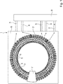
- Fig. 1 shows a schematic view of a first embodiment of an inductive position sensor 1 according to the invention.
- the inductive position sensor 1 comprises a transmit coil 2, an absolute position receive coil pair 3, 4, a high-resolution receive coil pair 5,6 and a conductive moving target 7.
- the absolute position receive coil pair 3, 4 and the high-resolution receive coil pair 5, 6 together define a measurement area of the inductive position sensor 1 and the moving target 7 can move in this measurement area.
- the first embodiment shown in Fig.1 refers to a radial inductive position sensor 1 and the measurement area is a 360° circle.
- the absolute position coil pair 3, 4 has a first sine receive coil 3 and a first cosine receive coil 4, both 3, 4 having one period over the measurement area of the inductive position sensor 1.
- the high-resolution position receive coil pair 5, 6 has a second sine receive coil 5 and a second cosine receive coil 6, both 5, 6 having at least two periods over the measurement area of the inductive position sensor 1. According to the embodiment shown in Fig. 1 the second sine receive coil 5 and a second cosine receive coil 6 each have 8-periods over the measurement area.
- the absolute position receive coil pair 3, 4 and the high-resolution position receive coil pair 5, 6 are arranged in the same area of a printed-circuit board 8 of the inductive position sensor 1.
- the inductive position sensor 1 shown in Fig. 1 further comprises a signal processing unit 9, for providing a signal to the at least one transmit coil 2 and for processing the signals of the absolute position receive coil pair 3, 4 and the high-resolution receive coil pair 5, 6.
- the signal processing unit 9 is externally connected to the printed-circuit board 8 of the inductive position sensor 1.
- the signal processing unit 9 is arranged on the same printed-circuit board 8 as the inductive position sensor 1. The connections between the signal processing unit 9 and the transmit coil 2, the absolute position receive coil pair 3, 4 and the high-resolution receive coil pair 5, 6 have been numbered identically to the respective coil.
- the signal processing unit 9 provides an excitation current to the transmit coil 2, which creates an electro-magnetic field due to the excitation current.
- the conductive moving target 7 is located inside this created electro-magnetic field of the transmit coil 2 and therefore modifies the electro-magnetic field due to eddy currents induced into the conductive moving target 7.
- the absolute position receive coil pair 3, 4 and the high-resolution receive coil pair 5, 6 can sense the modifications in the electro-magnetic field due to the conductive moving target 7 and the position of the conductive moving target 7.
- the signals of the absolute position receive coil pair 3, 4 and the high-resolution receive coil pair 5, 6 are used by the signal processing unit 9 to determine the absolute position and the high-resolution position of the conductive moving target 7 in the measurement area.
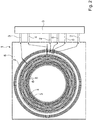
- Fig. 2 shows a schematic view of a second embodiment of an inductive position sensor 1 according to the invention.
- the second embodiment shown in Fig. 2 differs from the first embodiment shown in Fig.1 in that the inductive position sensor comprises two transmit coils 2 and in that the second sine receive coil 5 and a second cosine receive coil 6 each have 32-periods over the measurement area. Otherwise, the second embodiment corresponds to the first embodiment.
- the implementation of the high-resolution absolute sensor 1 with a 32-periodic receive coil pair 5, 6, a 1x360 absolute receive coil pair 3,4 and one shared signal processing unit 9 is shown in Fig. 2 .
- the target must be designed to generate signal for both high-resolution receive coil pair 5, 6 and absolute position receive coil pair 3, 4.
- the accuracy and robustness over tolerances will depend on the target configuration. Below are some implementation examples.
- Fig. 3 shows a first embodiment of a conductive moving target 7.
- the conductive moving target 7 comprises multiple sections 12 spaced apart from each other.
- the multiple sections 12 of the conductive moving target 7 have the same shape and spacing.
- One or more portions of the incremental n-period sensor target 7 are removed to generate sufficient signal on the 1-periodic absolute position receive coil pair 3, 4.
- Fig. 4 shows a second embodiment of a conductive moving target 7.
- Fig. 4 shows the upper and lower side of a substrate, wherein one side comprises a first target element 10 and the other side comprises a second target element 11, wherein the shape of the first target element 10 is different to the shape of the at least one second target element 11.
- the first target element 10 comprises multiple sections 12, spaced apart from each other.
- the multiple sections 12 of the conductive moving target 7 have the same shape and spacing and cover the complete circumference of the circular substrate building the conductive moving target 7.
- the multiple sections 12 of the first target element 10 cover the complete measurement area of the inductive position sensor 1.
- the second target element 11 has a semi-circular shape and overs a half-circle of the circular substrate of the conductive moving target 7.
- Fig. 4 shows the two sides of the same substrate of the same conductive moving target 7.
- Fig. 4 shows high-resolution segments 12 for the n-periodic receive coil pair 5, 6 and stacked target 11 for the 1-periodic absolute position receive coil pair 3, 4.
- Fig. 5 shows a third embodiment of a conductive moving target 7.
- the third embodiment of the conductive moving target 7 shown in Fig. 5 differs from the second embodiment of the conductive moving target 7 shown in Fig. 4 in that the second element 11 has the shape of an arc segment of a full ring, which is arranged on the same side as the first element 10 comprising the segments 12. Furthermore, the first element 10 and the second element 11 of the conductive moving target 7 are arranged next to each other, particularly the second element 11 is arranged inside the first element 10, and the first element 10 and the second element 11 do not overlap.
- Fig. 6 shows a fourth embodiment of a conductive moving target 7.
- the fourth embodiment of the conductive moving target 7 shown in Fig. 6 differs from the third embodiment of the conductive moving target 7 shown in Fig. 5 in that the second element 11 has a rectangular shape and overlaps with the first element 10.
- the first element 10 comprising the segments 12 completely overlaps the second element 11 if the gaps between the segments 12 are considered to belong to the first element 10.
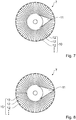
- Fig. 7 shows a fifth embodiment of a conductive moving target 7.
- the fifth embodiment of the conductive moving target 7 shown in Fig. 7 differs from the fourth embodiment of the conductive moving target 7 shown in Fig. 6 in that the second element 11 has the shape of an arrow.
- Fig. 8 shows a sixth embodiment of a conductive moving target 7, wherein the second element 11 has a bigger arrow shape compared to the fifth embodiment shown in Fig. 7 .
- Figs. 9a and 9b show a target configuration comparisons for:
- Fig. 9a and 9b show a performance comparison based on 32X coil.
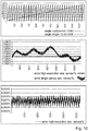
- Fig. 10 shows a high-resolution output after processing, particularly signal plot of 32 periodic high-resolution sensor and processed high resolution absolute sensor.
- Fig. 11 shows a schematic view of a third embodiment of an inductive position sensor 1 according to the invention.
- the inductive position sensor 1 shown in Fig. 11 is a linear position sensor with a straight measurement area, along which the conductive target 7 moves. Otherwise, the third embodiment of the inductive position sensor 1 shown in Fig. 11 corresponds to the first embodiment of the inductive position sensor 1 shown in Fig. 1 .
Landscapes
- Physics & Mathematics (AREA)
- General Physics & Mathematics (AREA)
- Engineering & Computer Science (AREA)
- Power Engineering (AREA)
- Transmission And Conversion Of Sensor Element Output (AREA)
Priority Applications (4)
| Application Number | Priority Date | Filing Date | Title |
|---|---|---|---|
| JP2021114325A JP2022016420A (ja) | 2020-07-10 | 2021-07-09 | 少なくとも1つの送信コイル、絶対位置受信コイル対、高分解能位置受信コイル対、および導電性移動ターゲットを備えた誘導位置センサ |
| US17/371,908 US20220011085A1 (en) | 2020-07-10 | 2021-07-09 | Inductive position sensor comprising at least one transmit coil, an absolute position receive coil pair, a high-resolution position receive coil pair and a conductive moving target |
| CN202110776584.1A CN113984093B (zh) | 2020-07-10 | 2021-07-09 | 电感式位置传感器 |
| US18/618,193 US12474154B2 (en) | 2020-07-10 | 2024-03-27 | Inductive position sensor comprising at least one transmit coil, an absolute position receive coil pair, a high-resolution position receive coil pair and a conductive moving target |
Applications Claiming Priority (1)
| Application Number | Priority Date | Filing Date | Title |
|---|---|---|---|
| EP20185164 | 2020-07-10 |
Publications (2)
| Publication Number | Publication Date |
|---|---|
| EP3936829A1 true EP3936829A1 (de) | 2022-01-12 |
| EP3936829B1 EP3936829B1 (de) | 2023-08-30 |
Family
ID=71575134
Family Applications (1)
| Application Number | Title | Priority Date | Filing Date |
|---|---|---|---|
| EP21178772.6A Active EP3936829B1 (de) | 2020-07-10 | 2021-06-10 | Induktiver positionssensor mit mindestens einer sendespule, einem absolutpositionsempfangsspulenpaar, einem hochauflösenden positionsbestimmungsspulenpaar und einem leitfähigen geber |
Country Status (4)
| Country | Link |
|---|---|
| US (2) | US20220011085A1 (de) |
| EP (1) | EP3936829B1 (de) |
| JP (1) | JP2022016420A (de) |
| CN (1) | CN113984093B (de) |
Cited By (1)
| Publication number | Priority date | Publication date | Assignee | Title |
|---|---|---|---|---|
| EP4632328A1 (de) * | 2024-04-11 | 2025-10-15 | Robert Bosch GmbH | Induktive sensoranordnung zur erfassung einer bewegung eines beweglichen körpers |
Families Citing this family (7)
| Publication number | Priority date | Publication date | Assignee | Title |
|---|---|---|---|---|
| CN114838655B (zh) * | 2022-04-12 | 2023-04-07 | 北京科技大学 | 一种多周期双极型电磁感应式角度传感器 |
| CN115060159B (zh) * | 2022-06-02 | 2025-08-05 | 道芯科技(南京)有限公司 | 电感式角度传感器 |
| CN115435669A (zh) * | 2022-09-13 | 2022-12-06 | Oppo广东移动通信有限公司 | 测量装置及电子设备 |
| CN115435668A (zh) * | 2022-09-13 | 2022-12-06 | Oppo广东移动通信有限公司 | 测量装置及电子设备 |
| GB2626041A (en) * | 2023-01-09 | 2024-07-10 | Cambridge Integrated Circuits Ltd | Position sensing |
| JP2026009506A (ja) * | 2024-07-08 | 2026-01-21 | 多摩川精機株式会社 | インダクティブエンコーダ |
| US20260049848A1 (en) * | 2024-08-15 | 2026-02-19 | Schneider Electric USA, Inc. | Contact-less linear displacement measurement pcb system for electrical protective devices |
Citations (5)
| Publication number | Priority date | Publication date | Assignee | Title |
|---|---|---|---|---|
| US6111402A (en) * | 1996-11-29 | 2000-08-29 | Dr. Johannes Heidenhain Gmbh | Position measuring instrument having a scanning element with multiple scanning tracks |
| US20040227644A1 (en) * | 2003-05-15 | 2004-11-18 | Yingjie Lin | Linear position sensor |
| US20160169717A1 (en) * | 2013-08-12 | 2016-06-16 | Victor Zhitomirsky | Position sensor |
| CN104061854B (zh) * | 2014-05-11 | 2016-08-24 | 浙江大学 | 用于电磁感应式角度传感器的pcb线圈及角度测量方法 |
| US20190331541A1 (en) * | 2016-12-12 | 2019-10-31 | Integrated Device Technology, Inc. | Ultra-thin combined inductive torque and angle sensor for steering wheel position sensing |
Family Cites Families (15)
| Publication number | Priority date | Publication date | Assignee | Title |
|---|---|---|---|---|
| DE19941464A1 (de) * | 1999-09-01 | 2001-03-15 | Hella Kg Hueck & Co | Induktiver Positionssensor |
| JP4615955B2 (ja) * | 2004-10-12 | 2011-01-19 | 株式会社ミツトヨ | 誘導型変位検出装置 |
| DE102006046531A1 (de) * | 2006-09-29 | 2008-04-03 | Dr. Johannes Heidenhain Gmbh | Drehgeber und Verfahren zu dessen Betrieb |
| JP4997213B2 (ja) * | 2008-11-11 | 2012-08-08 | 愛三工業株式会社 | レゾルバ |
| GB2500522B (en) * | 2010-12-24 | 2014-07-16 | Cambridge Integrated Circuits Ltd | Position Sensing Transducer |
| US9157768B2 (en) * | 2013-03-04 | 2015-10-13 | Texas Instruments Incorporated | Inductive sensing including inductance multiplication with series connected coils |
| US9677913B2 (en) * | 2014-04-28 | 2017-06-13 | Microsemi Corporation | Inductive displacement sensor |
| FR3031588B1 (fr) * | 2015-01-13 | 2018-11-16 | Hutchinson | Capteurs inductifs de deplacement |
| FR3031589B1 (fr) * | 2015-01-13 | 2018-11-16 | Hutchinson | Capteurs inductifs de deplacement |
| FR3031586B1 (fr) * | 2015-01-13 | 2017-02-10 | Dymeo | Capteurs inductifs de deplacement |
| DE102015220645A1 (de) * | 2015-10-22 | 2017-04-27 | Robert Bosch Gmbh | Drehwinkelsensor |
| CN108571986A (zh) * | 2017-03-07 | 2018-09-25 | 赛卓电子科技(上海)有限公司 | 位移传感器 |
| US11079291B2 (en) * | 2018-04-10 | 2021-08-03 | Semiconductor Components Industries, Llc | Inductive position sensor |
| US20200149927A1 (en) * | 2018-11-14 | 2020-05-14 | Yanchen Zhang | Inductive displacement sensor |
| CN110487162B (zh) * | 2019-09-29 | 2020-09-08 | 桂林广陆数字测控有限公司 | 混合定位电磁感应式位移传感器 |
-
2021
- 2021-06-10 EP EP21178772.6A patent/EP3936829B1/de active Active
- 2021-07-09 JP JP2021114325A patent/JP2022016420A/ja active Pending
- 2021-07-09 US US17/371,908 patent/US20220011085A1/en not_active Abandoned
- 2021-07-09 CN CN202110776584.1A patent/CN113984093B/zh active Active
-
2024
- 2024-03-27 US US18/618,193 patent/US12474154B2/en active Active
Patent Citations (5)
| Publication number | Priority date | Publication date | Assignee | Title |
|---|---|---|---|---|
| US6111402A (en) * | 1996-11-29 | 2000-08-29 | Dr. Johannes Heidenhain Gmbh | Position measuring instrument having a scanning element with multiple scanning tracks |
| US20040227644A1 (en) * | 2003-05-15 | 2004-11-18 | Yingjie Lin | Linear position sensor |
| US20160169717A1 (en) * | 2013-08-12 | 2016-06-16 | Victor Zhitomirsky | Position sensor |
| CN104061854B (zh) * | 2014-05-11 | 2016-08-24 | 浙江大学 | 用于电磁感应式角度传感器的pcb线圈及角度测量方法 |
| US20190331541A1 (en) * | 2016-12-12 | 2019-10-31 | Integrated Device Technology, Inc. | Ultra-thin combined inductive torque and angle sensor for steering wheel position sensing |
Cited By (1)
| Publication number | Priority date | Publication date | Assignee | Title |
|---|---|---|---|---|
| EP4632328A1 (de) * | 2024-04-11 | 2025-10-15 | Robert Bosch GmbH | Induktive sensoranordnung zur erfassung einer bewegung eines beweglichen körpers |
Also Published As
| Publication number | Publication date |
|---|---|
| US20220011085A1 (en) | 2022-01-13 |
| JP2022016420A (ja) | 2022-01-21 |
| US12474154B2 (en) | 2025-11-18 |
| CN113984093A (zh) | 2022-01-28 |
| CN113984093B (zh) | 2026-01-13 |
| US20240230307A1 (en) | 2024-07-11 |
| EP3936829B1 (de) | 2023-08-30 |
Similar Documents
| Publication | Publication Date | Title |
|---|---|---|
| EP3936829B1 (de) | Induktiver positionssensor mit mindestens einer sendespule, einem absolutpositionsempfangsspulenpaar, einem hochauflösenden positionsbestimmungsspulenpaar und einem leitfähigen geber | |
| US7190158B2 (en) | Inductive angle-of-rotation sensor and rotary transducer equipped with the same | |
| US9470505B2 (en) | Position sensing transducer | |
| US8278911B2 (en) | Inductive angle-of-rotation sensor and method for operating an inductive angle-of-rotation sensor | |
| US9383184B2 (en) | Inductive position-measuring device | |
| US20250093183A1 (en) | Position sensor system | |
| EP1931946B1 (de) | Positionsdetektion unter verwendung eines magnetsensorarrays | |
| US8129985B2 (en) | Position encoder | |
| JP7152280B2 (ja) | 電磁誘導式エンコーダ | |
| US20230152075A1 (en) | Radial inductive position sensor for detecting a rotational movement, high-resolution position sensor system and torque sensor system | |
| CN101421589B (zh) | 转向装置位置检测系统和方法 | |
| CN116635696B (zh) | 高分辨率角感应传感器及相关联的使用方法 | |
| EP3479072B1 (de) | Induktiver positionsgeber | |
| US20130257417A1 (en) | Position sensing transducer | |
| US12111220B2 (en) | Sensor assembly for sensing a steering torque and an absolute angular position, and sensor device having said sensor assembly | |
| US9835476B2 (en) | Scanning element for an inductive angle-measuring device | |
| CN116026231A (zh) | 感应式角度测量装置 | |
| CN112740000B (zh) | 用于机动车辆转向系统的感应角度传感器 | |
| EP4086586B1 (de) | Positionscodierer | |
| KR20200063071A (ko) | 전자식 스로틀 컨트롤을 위한 인덕티브 포지션 센서 | |
| US20240053171A1 (en) | Inductive sensor assembly | |
| US12163807B2 (en) | Reliable position sensor | |
| US20210348952A1 (en) | Sensor Unit for a Sensor/Transmitter System and a Sensor/Transmitter System Having Such a Sensor Unit | |
| CN121488141A (zh) | 具有优化尺寸的感应传感器 |
Legal Events
| Date | Code | Title | Description |
|---|---|---|---|
| PUAI | Public reference made under article 153(3) epc to a published international application that has entered the european phase |
Free format text: ORIGINAL CODE: 0009012 |
|
| STAA | Information on the status of an ep patent application or granted ep patent |
Free format text: STATUS: THE APPLICATION HAS BEEN PUBLISHED |
|
| AK | Designated contracting states |
Kind code of ref document: A1 Designated state(s): AL AT BE BG CH CY CZ DE DK EE ES FI FR GB GR HR HU IE IS IT LI LT LU LV MC MK MT NL NO PL PT RO RS SE SI SK SM TR |
|
| B565 | Issuance of search results under rule 164(2) epc |
Effective date: 20211105 |
|
| STAA | Information on the status of an ep patent application or granted ep patent |
Free format text: STATUS: REQUEST FOR EXAMINATION WAS MADE |
|
| 17P | Request for examination filed |
Effective date: 20220711 |
|
| RBV | Designated contracting states (corrected) |
Designated state(s): AL AT BE BG CH CY CZ DE DK EE ES FI FR GB GR HR HU IE IS IT LI LT LU LV MC MK MT NL NO PL PT RO RS SE SI SK SM TR |
|
| GRAP | Despatch of communication of intention to grant a patent |
Free format text: ORIGINAL CODE: EPIDOSNIGR1 |
|
| STAA | Information on the status of an ep patent application or granted ep patent |
Free format text: STATUS: GRANT OF PATENT IS INTENDED |
|
| INTG | Intention to grant announced |
Effective date: 20230331 |
|
| GRAS | Grant fee paid |
Free format text: ORIGINAL CODE: EPIDOSNIGR3 |
|
| GRAA | (expected) grant |
Free format text: ORIGINAL CODE: 0009210 |
|
| STAA | Information on the status of an ep patent application or granted ep patent |
Free format text: STATUS: THE PATENT HAS BEEN GRANTED |
|
| AK | Designated contracting states |
Kind code of ref document: B1 Designated state(s): AL AT BE BG CH CY CZ DE DK EE ES FI FR GB GR HR HU IE IS IT LI LT LU LV MC MK MT NL NO PL PT RO RS SE SI SK SM TR |
|
| REG | Reference to a national code |
Ref country code: GB Ref legal event code: FG4D |
|
| REG | Reference to a national code |
Ref country code: CH Ref legal event code: EP |
|
| REG | Reference to a national code |
Ref country code: DE Ref legal event code: R096 Ref document number: 602021004630 Country of ref document: DE |
|
| REG | Reference to a national code |
Ref country code: IE Ref legal event code: FG4D |
|
| REG | Reference to a national code |
Ref country code: LT Ref legal event code: MG9D |
|
| REG | Reference to a national code |
Ref country code: NL Ref legal event code: MP Effective date: 20230830 |
|
| REG | Reference to a national code |
Ref country code: AT Ref legal event code: MK05 Ref document number: 1605984 Country of ref document: AT Kind code of ref document: T Effective date: 20230830 |
|
| PG25 | Lapsed in a contracting state [announced via postgrant information from national office to epo] |
Ref country code: GR Free format text: LAPSE BECAUSE OF FAILURE TO SUBMIT A TRANSLATION OF THE DESCRIPTION OR TO PAY THE FEE WITHIN THE PRESCRIBED TIME-LIMIT Effective date: 20231201 |
|
| PG25 | Lapsed in a contracting state [announced via postgrant information from national office to epo] |
Ref country code: IS Free format text: LAPSE BECAUSE OF FAILURE TO SUBMIT A TRANSLATION OF THE DESCRIPTION OR TO PAY THE FEE WITHIN THE PRESCRIBED TIME-LIMIT Effective date: 20231230 |
|
| PG25 | Lapsed in a contracting state [announced via postgrant information from national office to epo] |
Ref country code: SE Free format text: LAPSE BECAUSE OF FAILURE TO SUBMIT A TRANSLATION OF THE DESCRIPTION OR TO PAY THE FEE WITHIN THE PRESCRIBED TIME-LIMIT Effective date: 20230830 Ref country code: RS Free format text: LAPSE BECAUSE OF FAILURE TO SUBMIT A TRANSLATION OF THE DESCRIPTION OR TO PAY THE FEE WITHIN THE PRESCRIBED TIME-LIMIT Effective date: 20230830 Ref country code: NO Free format text: LAPSE BECAUSE OF FAILURE TO SUBMIT A TRANSLATION OF THE DESCRIPTION OR TO PAY THE FEE WITHIN THE PRESCRIBED TIME-LIMIT Effective date: 20231130 Ref country code: LV Free format text: LAPSE BECAUSE OF FAILURE TO SUBMIT A TRANSLATION OF THE DESCRIPTION OR TO PAY THE FEE WITHIN THE PRESCRIBED TIME-LIMIT Effective date: 20230830 Ref country code: LT Free format text: LAPSE BECAUSE OF FAILURE TO SUBMIT A TRANSLATION OF THE DESCRIPTION OR TO PAY THE FEE WITHIN THE PRESCRIBED TIME-LIMIT Effective date: 20230830 Ref country code: IS Free format text: LAPSE BECAUSE OF FAILURE TO SUBMIT A TRANSLATION OF THE DESCRIPTION OR TO PAY THE FEE WITHIN THE PRESCRIBED TIME-LIMIT Effective date: 20231230 Ref country code: HR Free format text: LAPSE BECAUSE OF FAILURE TO SUBMIT A TRANSLATION OF THE DESCRIPTION OR TO PAY THE FEE WITHIN THE PRESCRIBED TIME-LIMIT Effective date: 20230830 Ref country code: GR Free format text: LAPSE BECAUSE OF FAILURE TO SUBMIT A TRANSLATION OF THE DESCRIPTION OR TO PAY THE FEE WITHIN THE PRESCRIBED TIME-LIMIT Effective date: 20231201 Ref country code: FI Free format text: LAPSE BECAUSE OF FAILURE TO SUBMIT A TRANSLATION OF THE DESCRIPTION OR TO PAY THE FEE WITHIN THE PRESCRIBED TIME-LIMIT Effective date: 20230830 Ref country code: AT Free format text: LAPSE BECAUSE OF FAILURE TO SUBMIT A TRANSLATION OF THE DESCRIPTION OR TO PAY THE FEE WITHIN THE PRESCRIBED TIME-LIMIT Effective date: 20230830 |
|
| PG25 | Lapsed in a contracting state [announced via postgrant information from national office to epo] |
Ref country code: PL Free format text: LAPSE BECAUSE OF FAILURE TO SUBMIT A TRANSLATION OF THE DESCRIPTION OR TO PAY THE FEE WITHIN THE PRESCRIBED TIME-LIMIT Effective date: 20230830 Ref country code: NL Free format text: LAPSE BECAUSE OF FAILURE TO SUBMIT A TRANSLATION OF THE DESCRIPTION OR TO PAY THE FEE WITHIN THE PRESCRIBED TIME-LIMIT Effective date: 20230830 |
|
| PG25 | Lapsed in a contracting state [announced via postgrant information from national office to epo] |
Ref country code: ES Free format text: LAPSE BECAUSE OF FAILURE TO SUBMIT A TRANSLATION OF THE DESCRIPTION OR TO PAY THE FEE WITHIN THE PRESCRIBED TIME-LIMIT Effective date: 20230830 |
|
| PG25 | Lapsed in a contracting state [announced via postgrant information from national office to epo] |
Ref country code: SM Free format text: LAPSE BECAUSE OF FAILURE TO SUBMIT A TRANSLATION OF THE DESCRIPTION OR TO PAY THE FEE WITHIN THE PRESCRIBED TIME-LIMIT Effective date: 20230830 Ref country code: RO Free format text: LAPSE BECAUSE OF FAILURE TO SUBMIT A TRANSLATION OF THE DESCRIPTION OR TO PAY THE FEE WITHIN THE PRESCRIBED TIME-LIMIT Effective date: 20230830 Ref country code: ES Free format text: LAPSE BECAUSE OF FAILURE TO SUBMIT A TRANSLATION OF THE DESCRIPTION OR TO PAY THE FEE WITHIN THE PRESCRIBED TIME-LIMIT Effective date: 20230830 Ref country code: EE Free format text: LAPSE BECAUSE OF FAILURE TO SUBMIT A TRANSLATION OF THE DESCRIPTION OR TO PAY THE FEE WITHIN THE PRESCRIBED TIME-LIMIT Effective date: 20230830 Ref country code: DK Free format text: LAPSE BECAUSE OF FAILURE TO SUBMIT A TRANSLATION OF THE DESCRIPTION OR TO PAY THE FEE WITHIN THE PRESCRIBED TIME-LIMIT Effective date: 20230830 Ref country code: CZ Free format text: LAPSE BECAUSE OF FAILURE TO SUBMIT A TRANSLATION OF THE DESCRIPTION OR TO PAY THE FEE WITHIN THE PRESCRIBED TIME-LIMIT Effective date: 20230830 Ref country code: SK Free format text: LAPSE BECAUSE OF FAILURE TO SUBMIT A TRANSLATION OF THE DESCRIPTION OR TO PAY THE FEE WITHIN THE PRESCRIBED TIME-LIMIT Effective date: 20230830 Ref country code: PT Free format text: LAPSE BECAUSE OF FAILURE TO SUBMIT A TRANSLATION OF THE DESCRIPTION OR TO PAY THE FEE WITHIN THE PRESCRIBED TIME-LIMIT Effective date: 20240102 |
|
| PG25 | Lapsed in a contracting state [announced via postgrant information from national office to epo] |
Ref country code: IT Free format text: LAPSE BECAUSE OF FAILURE TO SUBMIT A TRANSLATION OF THE DESCRIPTION OR TO PAY THE FEE WITHIN THE PRESCRIBED TIME-LIMIT Effective date: 20230830 |
|
| REG | Reference to a national code |
Ref country code: DE Ref legal event code: R097 Ref document number: 602021004630 Country of ref document: DE |
|
| PLBE | No opposition filed within time limit |
Free format text: ORIGINAL CODE: 0009261 |
|
| STAA | Information on the status of an ep patent application or granted ep patent |
Free format text: STATUS: NO OPPOSITION FILED WITHIN TIME LIMIT |
|
| PG25 | Lapsed in a contracting state [announced via postgrant information from national office to epo] |
Ref country code: SI Free format text: LAPSE BECAUSE OF FAILURE TO SUBMIT A TRANSLATION OF THE DESCRIPTION OR TO PAY THE FEE WITHIN THE PRESCRIBED TIME-LIMIT Effective date: 20230830 |
|
| 26N | No opposition filed |
Effective date: 20240603 |
|
| PG25 | Lapsed in a contracting state [announced via postgrant information from national office to epo] |
Ref country code: BG Free format text: LAPSE BECAUSE OF FAILURE TO SUBMIT A TRANSLATION OF THE DESCRIPTION OR TO PAY THE FEE WITHIN THE PRESCRIBED TIME-LIMIT Effective date: 20230830 |
|
| PG25 | Lapsed in a contracting state [announced via postgrant information from national office to epo] |
Ref country code: BG Free format text: LAPSE BECAUSE OF FAILURE TO SUBMIT A TRANSLATION OF THE DESCRIPTION OR TO PAY THE FEE WITHIN THE PRESCRIBED TIME-LIMIT Effective date: 20230830 |
|
| PG25 | Lapsed in a contracting state [announced via postgrant information from national office to epo] |
Ref country code: MC Free format text: LAPSE BECAUSE OF FAILURE TO SUBMIT A TRANSLATION OF THE DESCRIPTION OR TO PAY THE FEE WITHIN THE PRESCRIBED TIME-LIMIT Effective date: 20230830 |
|
| REG | Reference to a national code |
Ref country code: CH Ref legal event code: PL |
|
| PG25 | Lapsed in a contracting state [announced via postgrant information from national office to epo] |
Ref country code: LU Free format text: LAPSE BECAUSE OF NON-PAYMENT OF DUE FEES Effective date: 20240610 |
|
| PG25 | Lapsed in a contracting state [announced via postgrant information from national office to epo] |
Ref country code: IE Free format text: LAPSE BECAUSE OF NON-PAYMENT OF DUE FEES Effective date: 20240610 |
|
| PG25 | Lapsed in a contracting state [announced via postgrant information from national office to epo] |
Ref country code: BE Free format text: LAPSE BECAUSE OF NON-PAYMENT OF DUE FEES Effective date: 20240630 Ref country code: CH Free format text: LAPSE BECAUSE OF NON-PAYMENT OF DUE FEES Effective date: 20240630 |
|
| PG25 | Lapsed in a contracting state [announced via postgrant information from national office to epo] |
Ref country code: FR Free format text: LAPSE BECAUSE OF NON-PAYMENT OF DUE FEES Effective date: 20240630 |
|
| REG | Reference to a national code |
Ref country code: BE Ref legal event code: MM Effective date: 20240630 |
|
| PGFP | Annual fee paid to national office [announced via postgrant information from national office to epo] |
Ref country code: DE Payment date: 20250626 Year of fee payment: 5 |
|
| PG25 | Lapsed in a contracting state [announced via postgrant information from national office to epo] |
Ref country code: CY Free format text: LAPSE BECAUSE OF FAILURE TO SUBMIT A TRANSLATION OF THE DESCRIPTION OR TO PAY THE FEE WITHIN THE PRESCRIBED TIME-LIMIT; INVALID AB INITIO Effective date: 20210610 |
|
| GBPC | Gb: european patent ceased through non-payment of renewal fee |
Effective date: 20250610 |
|
| PG25 | Lapsed in a contracting state [announced via postgrant information from national office to epo] |
Ref country code: HU Free format text: LAPSE BECAUSE OF FAILURE TO SUBMIT A TRANSLATION OF THE DESCRIPTION OR TO PAY THE FEE WITHIN THE PRESCRIBED TIME-LIMIT; INVALID AB INITIO Effective date: 20210610 |
|
| PG25 | Lapsed in a contracting state [announced via postgrant information from national office to epo] |
Ref country code: GB Free format text: LAPSE BECAUSE OF NON-PAYMENT OF DUE FEES Effective date: 20250610 |