EP3936882A1 - Système d'imagerie par résonance magnétique et procédé avec un calibrage de fréquence basé sur un signal d'un système de positionnement par géo-satellite - Google Patents
Système d'imagerie par résonance magnétique et procédé avec un calibrage de fréquence basé sur un signal d'un système de positionnement par géo-satellite Download PDFInfo
- Publication number
- EP3936882A1 EP3936882A1 EP20184482.6A EP20184482A EP3936882A1 EP 3936882 A1 EP3936882 A1 EP 3936882A1 EP 20184482 A EP20184482 A EP 20184482A EP 3936882 A1 EP3936882 A1 EP 3936882A1
- Authority
- EP
- European Patent Office
- Prior art keywords
- frequency
- magnetic resonance
- signal
- mri system
- resonance signal
- Prior art date
- Legal status (The legal status is an assumption and is not a legal conclusion. Google has not performed a legal analysis and makes no representation as to the accuracy of the status listed.)
- Withdrawn
Links
Images
Classifications
-
- G—PHYSICS
- G01—MEASURING; TESTING
- G01R—MEASURING ELECTRIC VARIABLES; MEASURING MAGNETIC VARIABLES
- G01R33/00—Arrangements or instruments for measuring magnetic variables
- G01R33/20—Arrangements or instruments for measuring magnetic variables involving magnetic resonance
- G01R33/28—Details of apparatus provided for in groups G01R33/44 - G01R33/64
- G01R33/32—Excitation or detection systems, e.g. using radio frequency signals
- G01R33/36—Electrical details, e.g. matching or coupling of the coil to the receiver
- G01R33/3692—Electrical details, e.g. matching or coupling of the coil to the receiver involving signal transmission without using electrically conductive connections, e.g. wireless communication or optical communication of the MR signal or an auxiliary signal other than the MR signal
-
- G—PHYSICS
- G01—MEASURING; TESTING
- G01R—MEASURING ELECTRIC VARIABLES; MEASURING MAGNETIC VARIABLES
- G01R33/00—Arrangements or instruments for measuring magnetic variables
- G01R33/20—Arrangements or instruments for measuring magnetic variables involving magnetic resonance
- G01R33/28—Details of apparatus provided for in groups G01R33/44 - G01R33/64
- G01R33/32—Excitation or detection systems, e.g. using radio frequency signals
- G01R33/36—Electrical details, e.g. matching or coupling of the coil to the receiver
- G01R33/3607—RF waveform generators, e.g. frequency generators, amplitude-, frequency- or phase modulators or shifters, pulse programmers, digital to analog converters for the RF signal, means for filtering or attenuating of the RF signal
-
- G—PHYSICS
- G01—MEASURING; TESTING
- G01R—MEASURING ELECTRIC VARIABLES; MEASURING MAGNETIC VARIABLES
- G01R33/00—Arrangements or instruments for measuring magnetic variables
- G01R33/20—Arrangements or instruments for measuring magnetic variables involving magnetic resonance
- G01R33/24—Arrangements or instruments for measuring magnetic variables involving magnetic resonance for measuring direction or magnitude of magnetic fields or magnetic flux
-
- G—PHYSICS
- G01—MEASURING; TESTING
- G01R—MEASURING ELECTRIC VARIABLES; MEASURING MAGNETIC VARIABLES
- G01R33/00—Arrangements or instruments for measuring magnetic variables
- G01R33/20—Arrangements or instruments for measuring magnetic variables involving magnetic resonance
- G01R33/28—Details of apparatus provided for in groups G01R33/44 - G01R33/64
- G01R33/32—Excitation or detection systems, e.g. using radio frequency signals
- G01R33/36—Electrical details, e.g. matching or coupling of the coil to the receiver
- G01R33/3621—NMR receivers or demodulators, e.g. preamplifiers, means for frequency modulation of the MR signal using a digital down converter, means for analog to digital conversion [ADC] or for filtering or processing of the MR signal such as bandpass filtering, resampling, decimation or interpolation
-
- G—PHYSICS
- G01—MEASURING; TESTING
- G01R—MEASURING ELECTRIC VARIABLES; MEASURING MAGNETIC VARIABLES
- G01R33/00—Arrangements or instruments for measuring magnetic variables
- G01R33/20—Arrangements or instruments for measuring magnetic variables involving magnetic resonance
- G01R33/44—Arrangements or instruments for measuring magnetic variables involving magnetic resonance using nuclear magnetic resonance [NMR]
- G01R33/48—NMR imaging systems
- G01R33/54—Signal processing systems, e.g. using pulse sequences ; Generation or control of pulse sequences; Operator console
- G01R33/56—Image enhancement or correction, e.g. subtraction or averaging techniques, e.g. improvement of signal-to-noise ratio and resolution
- G01R33/565—Correction of image distortions, e.g. due to magnetic field inhomogeneities
- G01R33/56563—Correction of image distortions, e.g. due to magnetic field inhomogeneities caused by a distortion of the main magnetic field B0, e.g. temporal variation of the magnitude or spatial inhomogeneity of B0
-
- G—PHYSICS
- G01—MEASURING; TESTING
- G01R—MEASURING ELECTRIC VARIABLES; MEASURING MAGNETIC VARIABLES
- G01R33/00—Arrangements or instruments for measuring magnetic variables
- G01R33/20—Arrangements or instruments for measuring magnetic variables involving magnetic resonance
- G01R33/44—Arrangements or instruments for measuring magnetic variables involving magnetic resonance using nuclear magnetic resonance [NMR]
- G01R33/48—NMR imaging systems
- G01R33/58—Calibration of imaging systems, e.g. using test probes, Phantoms; Calibration objects or fiducial markers such as active or passive RF coils surrounding an MR active material
- G01R33/583—Calibration of signal excitation or detection systems, e.g. for optimal RF excitation power or frequency
Definitions
- the invention relates to magnetic resonance imagining, MRI, systems, and in particular the measurement of, and setting of, the RF resonance frequency.
- Magnetic resonance imaging is a medical imaging technique used in radiology to form pictures of the anatomy and the physiological processes of the body.
- MRI scanners use strong magnetic fields, magnetic field gradients, and radio waves to generate images of the organs in the body.
- MRI is widely used in hospitals and clinics for medical diagnosis and staging and follow-up of disease without exposing the body to radiation.
- MRI is based on the ability of certain atomic nuclei to absorb radio frequency energy when placed in an external magnetic field.
- the resultant evolving spin polarization can induce an RF signal in a radio frequency coil and thereby be detected.
- Hydrogen atoms are most often used to generate a macroscopic polarization that is detected by antennas close to the subject being examined. Hydrogen atoms are naturally abundant in humans and other biological organisms, particularly in water and fat. For this reason, most MRI scans essentially map the location of water and fat in the body.
- Pulses of radio waves excite the nuclear spin energy transition, and magnetic field gradients localize the polarization in space.
- Pulses of radio waves excite the nuclear spin energy transition, and magnetic field gradients localize the polarization in space.
- different contrasts may be generated between tissues based on the relaxation properties of the hydrogen atoms therein.
- a primary candidate is an altered bulk magnetic susceptibility of the tissue being imaged.
- the resonance frequency (F0) to be used (for RF field synthesis and detection) during an MRI procedure is determined in a dedicated preparation phase (the so-called “F0 preparation phase") by analyzing the free induction decay (FID) of a sub-volume of the patient inside the imaging bore.
- the F0 preparation phase is often repeated even if the patient position stays the same. This makes F0 determination the most time-consuming of all preparation phases.
- a method of setting an RF operating frequency of an MRI system comprising:
- This method enables calibration of the master clock (e.g. a 10MHz clock) which is used to set the RF operating frequency corresponding to the Larmor frequency, F0 (e.g. 63.87MHz for a 1.5T field or 127.74MHz for a 3T field).
- Obtained calibration information basically involves determining the true frequency.
- a 10MHz signal source (the second frequency source) has an intended 10MHz clock signal output.
- the true clock signal output may differ from this.
- the generation of the RF operating frequency using the master clock signal can be adapted such that it has a known, desired, frequency, regardless of the actual frequency of the clock signal.
- the first reference frequency signal is for example obtained from a GPS system. This is a readily available source of a long term stable clock signal with off-the-shelf receiving circuitry. However, other geo-satellite systems may be used such as Galileo, DORIS, Glonass, Baidou).
- the second frequency source for example comprises an oven controlled crystal oscillator. This provides a stable short term (e.g. at least for the full duration of a scan) clock signal source.
- the calibration enables the actual frequency of the second frequency source to be known, and it can remain constant for the required duration. Longer term drifts in the second frequency source can thus be compensated by the external more long term stable source.
- the method may further comprise measuring a frequency of operation of the MRI system, comprising:
- This provides a measurement of the Larmor frequency using a source which is not controlled by the electronics of the MRI imaging system. Thus, it can be used to detect independently a drift in the main field (the B0 field) within the MR bore.
- the magnetic resonance signal probe may comprise a frequency reference which is calibrated by a signal obtained from a geo-satellite positioning system. This provides accurate measurement of the Larmor frequency.
- the method may comprise measuring a free induction decay with a subject in the imaging bore of the MRI system and also without a subject in an imaging bore of the MRI system. In this way, the effect of the subject on the field may also be determined. In this way, the three possible sources of drift in F0 are separated, and the way the frequency is influenced by the different factors can be better understood, and then better factored into an imaging workflow.
- the method may comprise placing an array of magnetic resonance signal probes into the imaging bore of the MRI system and measuring a free induction decay using each magnetic resonance signal probe. In this way, a distribution in 3D space may be obtained. This may be compared with the characteristics of the subject (e.g. their size and density distribution) to model the impact of the presence of the subject on the field strength and hence frequency.
- the method may comprise monitoring the temporal characteristics of the field detected by the probe thereby to detect subject-induced variations.
- the method may further comprise performing a resonant frequency calibration using the MRI system, and determining the master clock frequency based on the resonant frequency calibration and the measurement of the free induction decay using the magnetic resonance signal probe.
- the master clock frequency can be determined based on the both the internal system measurements and the external probe measurements.
- the required resonance frequency (e.g. as a multiple of the actual frequency generated by the second frequency source) can then be predicted and set very accurately.
- the invention also provides a method of measuring a frequency of operation of an MRI system, comprising:
- the frequency calibration described above may be used to provide a signal probe for accurately measuring an MRI operating frequency.
- the invention also provides a system for setting an operating frequency of an MRI system, comprising:
- the antenna may comprise a GPS antenna.
- the second frequency source may comprise an oven controlled crystal oscillator.
- the system may further comprise a magnetic resonance signal probe for insertion into the imaging bore of the MRI system for measuring a free induction decay.
- the probe for example comprises an MR-active substance and an RF coil to excite the magnetization and detect the magnetic resonance signal.
- the invention also provides a magnetic resonance signal probe for measuring a frequency of operation of an MRI system by measuring a free induction decay, comprising:
- the invention provides a method of setting an RF operating frequency of an MRI system which uses a first reference frequency signal, obtained from a geo-satellite positioning system, as a long term frequency reference.
- a second frequency source is calibrated using the first frequency reference signal and the second frequency reference source is then used as the master clock for the MRI system, for setting the RF operating frequency.
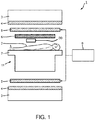
- Fig. 1 shows a conventional a MRI system 1 as well as an additional MR sensor 30.
- This MRI system 1 is used for MRI examination of a patient 2 in an examination area 18 within the bore of a superconducting magnet 3, which is used for generating a high static magnetic field.
- the patient 2 is positioned on a patient support 7, which may be driven into and out of the examination area 18 within the bore of the superconducting magnet 3.
- the MRI system 1 is only shown with its most fundamental components, i.e. components which are of relevance for the present invention.
- the MRI system 1 comprises a gradient coil 4 within the bore of the superconducting magnet 3 as well as RF transmit coils 5 and a RF receiver coil 6.
- the RF transmit coils 5 emit RF pulses, which are supplied from a RF transmitter 8, and generate a radio frequency magnetic field within the bore of the superconducting magnet 3.
- the received magnetic resonance signals are time-based amplitude signals, which are further Fourier transformed to frequency-based magnetic resonance spectrum signals and further processed for generating a magnetic resonance image of the nucleons of interest.
- the RF transmitter 8 comprises an RF amplifier for generating RF pulses and for forwarding these RF pulses to the RF transmit coil 5 of the MRI system 1. Further, the RF transmitter 8 typically comprises a capacitor bank which is coupled to the RF amplifier, for storing electric energy and for providing the RF amplifier with a current for generating the RF pulses. A mains power supply is coupled to the capacitor bank 10, for generating a charging current for charging the capacitor bank with electric energy.
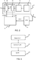
- Fig. 2 shows an example of the RF transmitter 8, comprising the RF amplifier 9 and the capacitor bank 10 coupled to the mains power supply 11.
- the RF amplifier 9 for example comprises an oven controlled crystal oscillator (OCXO) 24.
- OCXO oven controlled crystal oscillator
- Suitable oven controlled oscillators as integrated devices are available such as the Farnell (Trade Mark) model LFOCXO067293BULK. This provides a single component giving a 10 MHz reference with approximately a relative stability of 10 to 12.
- This level of stability is sufficient to rule out electronics drift as source for any observed F0 changes over a long time frame such as over weeks.
- the invention makes use of a geo-satellite receiver 20 such as a GPS receiver and its associated antenna 21.
- the antenna 21 is for example incorporated into the quench pipe.
- the GPS signal is used to extract a first reference frequency signal CLK1, obtained from the geo-satellite positioning system, as a long term frequency reference.
- the ranging codes and navigation messages which travel from the satellite to the receiver are modulated onto a carrier wave.
- a carrier wave In the case of the original GPS design, two frequencies are utilized; one at 1575.42 MHz (10.23 MHz ⁇ 154) called L1; and a second at 1227.60 MHz (10.23 MHz ⁇ 120), called L2. Either one of these carrier frequencies can be used as the long term frequency reference. Of course other geo-satellite systems may use different frequencies.
- the RF amplifier comprises the oscillator 24 for generating the master clock signal F_MC and a conversion unit 26 for generating the required Larmor frequency from the master clock signal.
- the oscillator 24 functions as a second frequency source.
- the master clock signal is for example a (desired/nominal) 10MHz clock signal.
- This master clock signal F_MC is an external clock reference for a digital phase locked loop transmitter. It allows the main output reference frequency F0 to have almost any value between 42 MHz and 300 MHz (1T - 7T), and any phase.
- a controller 22 is provided for calibrating the second frequency source using the first frequency reference signal. This calibration involves determining the actual frequency of the master clock signal F_MC (thus taking into account any affects of electronic drift) by using the reference signal of known frequency CLK1 as a reference. This provides calibration information which is then used to determine how the output signal F_MC is processed to derive the RF frequency F0.
- the second frequency reference source is used as the master clock for the MRI system, which master clock is used for setting the RF operating frequency F0, i.e. for RF synthesis and reception.
- the control signal "Control" for the conversion unit 26 is determined by the controller such that the correct operating frequency, i.e. the Larmor frequency, is generated from the master clock signal, based on the known the main field B0.
- the conversion unit 26 receives the 10 MHz reference clock frequency for the MRI complex transmit pulse F0 (frequency, time and phase).
- the phase, time and frequency of the signal F0 is obtained using a signal generation circuit which applies digital and/or analog amplification.
- the controller 22 provides timing signals, digital time codes, and digital and/or analog signals as the input control for the conversion unit 26 to process F_MC. Calculation of the control signals is performed in the digital domain using software.
- the frequency F0 is generated in the conversion unit 26 using a low-jitter high quality reference clock (quartz often) locked to the GPS signal.
- the frequency F0 is generated by a high precision state of the art digital synthesizer.
- This method enables calibration of the master clock (e.g. a 10MHz clock) which is used to set the RF operating frequency corresponding to the Larmor frequency, F0 (e.g. 63.87MHz for a 1.5T field or 127.74MHz for a 3T field).
- the master clock e.g. a 10MHz clock
- F0 e.g. 63.87MHz for a 1.5T field or 127.74MHz for a 3T field.
- the geo satellite system provides a highly stable oscillator which can be used as a frequency reference over a long time scale. This is combined with the short term stability of e.g. oven controlled crystal oscillators (OCXO). This improves the long term stability of measurement and also enables improved modelling and prediction of F0, since a highly probable source of frequency variation is eliminated, namely the electronics drift and ageing. It is currently not known how much the electronic frequency reference drifts over a longer timescale. This drift may not lead to image quality problems, since the MR frequency calibration is performed very often, even at intervals during the period of an individual scan. Nevertheless, it is suspected to be a substantial source of observed long term drifts of the measured resonance frequency.
- OXO oven controlled crystal oscillators
- the frequency calibration measure described above may be combined with the use of a dedicated MR signal probe 30 (shown in Fig. 1 ) placed inside the bore of the MRI system. This can be used to measure an FID signal from the probe independent from the MRI system. This enables measurement of the value of F0 without using exam time. It can also be used to differentiate between magnet drift and patient-induced changes.
- the dedicated probe may also have its frequency source calibrated using the geo-satellite clock signal in exactly the same way as explained above.
- the dedicated probe may comprise a frequency reference which is calibrated by a signal obtained from a geo-satellite positioning system.
- the dedicated signal probe thereby implements a method of measuring a frequency of operation of the MRI system, comprising:
- the MR signal probe 30 mainly consists of a small volume containing an MR-active substance and a RF coil to excite the magnetization and detect the MR signal.
- the control of the RF coil makes use of the frequency source which forms part of the probe.
- There are many known ways to build such a probe for example as discussed in Simon Gross, et al., "Dynamic nuclear magnetic resonance field sensing with part-per-trillion resolution", Nat Commun 7, 13702 (2016) doi:10.1038/ncomms13702 . Such designs can then be enhanced with the frequency calibration as explained above.
- Fluorine compound as active substance because it has a frequency which is close to the water frequency but different enough to allow simultaneous operation with the MRI system without interference.
- the probe could be placed behind the bore cover or under the patient table. Patient induced field variations could be distinguished from magnet drift by comparing measurements with and without the patient inside the bore which are taken within a short time period.
- Placing multiple probes around the imaging volume could be used to generate a model of the spatial variations of the patient-induced field changes. Furthermore, dynamic variations of the field may be used to determine patient physiology signals (respiration and heart beat)
- a first approach, for taking account of dynamic variations comprises:
- a second approach, for taking account of spatial variations, comprises:
- a third approach, for deriving patient physiology information comprises:
- the results of the changes of the measured frequency of the independent probe 30, together with the frequency determined by the conventional calibration "inside" the same patient can be used to model the expected resonance frequency for the measurement.
- the independent probe can predict in combination with the trained model the required resonance frequency for imaging probably very accurately.
- the aim of the model is to determine the resonance frequency F0 without time-consuming measurements.
- the model is for example a trained neural network or decision tree algorithm which predicts the expected F0.
- the training data for the model consist of the resonance frequency, detailed B0 maps of patients, additional patient data typically available during exam (such as weight, sex, etc.). Other parameters of the scan and its setting are also known and may be used such as the table position and field of view.
- Low resolution MR images which are less sensitive to F0 may be acquired for example for coil selection, and to give spatially and temporally resolved data of the field probe(s).
- Additional training data may comprise RF measurement-based data such as coil loading and coil coupling, which is acquired typically much faster than the measurement of the resonance frequency,
- the model may be trained with known datasets.
- the resonance frequency F0 has a spatial resolution since the underling B0 field varies with position. Typically, the resonance frequency is determined within a slice through the patient, and averaging over all slice volumes inside the patient is used to determined to derive the desired frequency. With spatial resolution, the resonance frequency may be measured at locations or areas which are most representative for the scan to be performed, e.g. the scan slice position.
- Fig. 3 shows a method of setting an RF operating frequency of an MRI system, comprising:
Landscapes
- Physics & Mathematics (AREA)
- Condensed Matter Physics & Semiconductors (AREA)
- General Physics & Mathematics (AREA)
- High Energy & Nuclear Physics (AREA)
- Engineering & Computer Science (AREA)
- Computer Networks & Wireless Communication (AREA)
- Health & Medical Sciences (AREA)
- General Health & Medical Sciences (AREA)
- Nuclear Medicine, Radiotherapy & Molecular Imaging (AREA)
- Radiology & Medical Imaging (AREA)
- Signal Processing (AREA)
- Magnetic Resonance Imaging Apparatus (AREA)
Priority Applications (5)
| Application Number | Priority Date | Filing Date | Title |
|---|---|---|---|
| EP20184482.6A EP3936882A1 (fr) | 2020-07-07 | 2020-07-07 | Système d'imagerie par résonance magnétique et procédé avec un calibrage de fréquence basé sur un signal d'un système de positionnement par géo-satellite |
| EP21732346.8A EP4179343B1 (fr) | 2020-07-07 | 2021-06-22 | Système d'imagerie par résonance magnétique et procédé avec un calibrage de fréquence basé sur un signal d'un système de positionnement par géo-satellite |
| CN202180048513.8A CN115803657B (zh) | 2020-07-07 | 2021-06-22 | Mri系统,特别是用于设置其rf工作频率的方法和系统 |
| US18/014,563 US12222411B2 (en) | 2020-07-07 | 2021-06-22 | Magnetic resonance imaging system and method using frequency calibration based on a signal from a geo-satellite positioning system |
| PCT/EP2021/066896 WO2022008223A1 (fr) | 2020-07-07 | 2021-06-22 | Système et procédé d'imagerie par résonance magnétique utilisant un étalonnage en fréquence sur la base d'un signal provenant d'un système de géo-positionnement par satellite |
Applications Claiming Priority (1)
| Application Number | Priority Date | Filing Date | Title |
|---|---|---|---|
| EP20184482.6A EP3936882A1 (fr) | 2020-07-07 | 2020-07-07 | Système d'imagerie par résonance magnétique et procédé avec un calibrage de fréquence basé sur un signal d'un système de positionnement par géo-satellite |
Publications (1)
| Publication Number | Publication Date |
|---|---|
| EP3936882A1 true EP3936882A1 (fr) | 2022-01-12 |
Family
ID=71523052
Family Applications (2)
| Application Number | Title | Priority Date | Filing Date |
|---|---|---|---|
| EP20184482.6A Withdrawn EP3936882A1 (fr) | 2020-07-07 | 2020-07-07 | Système d'imagerie par résonance magnétique et procédé avec un calibrage de fréquence basé sur un signal d'un système de positionnement par géo-satellite |
| EP21732346.8A Active EP4179343B1 (fr) | 2020-07-07 | 2021-06-22 | Système d'imagerie par résonance magnétique et procédé avec un calibrage de fréquence basé sur un signal d'un système de positionnement par géo-satellite |
Family Applications After (1)
| Application Number | Title | Priority Date | Filing Date |
|---|---|---|---|
| EP21732346.8A Active EP4179343B1 (fr) | 2020-07-07 | 2021-06-22 | Système d'imagerie par résonance magnétique et procédé avec un calibrage de fréquence basé sur un signal d'un système de positionnement par géo-satellite |
Country Status (4)
| Country | Link |
|---|---|
| US (1) | US12222411B2 (fr) |
| EP (2) | EP3936882A1 (fr) |
| CN (1) | CN115803657B (fr) |
| WO (1) | WO2022008223A1 (fr) |
Family Cites Families (9)
| Publication number | Priority date | Publication date | Assignee | Title |
|---|---|---|---|---|
| US5440313A (en) | 1993-05-27 | 1995-08-08 | Stellar Gps Corporation | GPS synchronized frequency/time source |
| JP4076490B2 (ja) * | 2003-10-30 | 2008-04-16 | ジーイー・メディカル・システムズ・グローバル・テクノロジー・カンパニー・エルエルシー | 直交検波方法および装置並びにmri装置 |
| EP1999480B1 (fr) * | 2006-03-24 | 2015-07-08 | The Medical College of Wisconsin, Inc. | Système et procédé de numérisation directe de signaux rmn |
| CN101688906B (zh) | 2007-06-19 | 2013-07-17 | 皇家飞利浦电子股份有限公司 | 核磁共振成像射频接收器 |
| US8605543B2 (en) * | 2007-09-21 | 2013-12-10 | Fairfield Industries Incorporated | Method and apparatus for correcting the timing function in a nodal seismic data acquisition unit |
| US8643444B2 (en) * | 2012-06-04 | 2014-02-04 | Broadcom Corporation | Common reference crystal systems |
| CN103955004B (zh) * | 2014-03-19 | 2017-04-12 | 吉林大学 | 四通道核磁共振信号全波采集系统及采集方法 |
| KR102376725B1 (ko) * | 2017-11-08 | 2022-03-21 | 삼성전자 주식회사 | Rf 칩을 연결하는 전송선로의 위상 측정 방법 및 이를 위한 장치 |
| US11175367B2 (en) * | 2018-08-10 | 2021-11-16 | General Electric Company | Methods and systems for estimating transmit attenuation for a magnetic resonance imaging scan |
-
2020
- 2020-07-07 EP EP20184482.6A patent/EP3936882A1/fr not_active Withdrawn
-
2021
- 2021-06-22 CN CN202180048513.8A patent/CN115803657B/zh active Active
- 2021-06-22 US US18/014,563 patent/US12222411B2/en active Active
- 2021-06-22 WO PCT/EP2021/066896 patent/WO2022008223A1/fr not_active Ceased
- 2021-06-22 EP EP21732346.8A patent/EP4179343B1/fr active Active
Non-Patent Citations (5)
| Title |
|---|
| "PULSEBLASTERDDS: PROGRAMMABLE TTL AND DDS RF PULSE GENERATOR", INTERNET CITATION, 10 March 2005 (2005-03-10), XP002361616, Retrieved from the Internet <URL:http://web.archive.org/web/20050310092154/http://www.spincore.com/pbdds_index.html> [retrieved on 20060105] * |
| FAN X ET AL: "Gaseous3He nuclear magnetic resonance probe for cryogenic environments", REVIEW OF SCIENTIFIC INSTRUMENTS, AIP, MELVILLE, NY, US, vol. 90, no. 8, 21 August 2019 (2019-08-21), XP012240173, ISSN: 0034-6748, [retrieved on 20190821], DOI: 10.1063/1.5099379 * |
| KLAUS BAHNER ET AL: "Multichannel magnetic resonance sounding with wirelessly operated coils - A design study", 3 March 2015 (2015-03-03), XP055761296, Retrieved from the Internet <URL:https://www.researchgate.net/profile/Jakob_Larsen8/publication/278685101_Multichannel_magnetic_resonance_sounding_with_wirelessly_operated_coils_-_A_design_study/links/5583e13508ae4738295bae5c/Multichannel-magnetic-resonance-sounding-with-wirelessly-operated-coils-A-design-study.pdf> [retrieved on 20201218] * |
| MARJANOVIC JOSIP ET AL: "A Reconfigurable Platform for Magnetic Resonance Data Acquisition and Processing", IEEE TRANSACTIONS ON MEDICAL IMAGING, IEEE SERVICE CENTER, PISCATAWAY, NJ, US, vol. 39, no. 4, 28 September 2019 (2019-09-28), pages 1138 - 1148, XP011781004, ISSN: 0278-0062, [retrieved on 20200401], DOI: 10.1109/TMI.2019.2944696 * |
| SIMON GROSS ET AL.: "Dynamic nuclear magnetic resonance field sensing with part-per-trillion resolution", NAT COMMUN, vol. 7, 2016, pages 13702 |
Also Published As
| Publication number | Publication date |
|---|---|
| EP4179343A1 (fr) | 2023-05-17 |
| CN115803657B (zh) | 2026-03-06 |
| US12222411B2 (en) | 2025-02-11 |
| US20230258750A1 (en) | 2023-08-17 |
| CN115803657A (zh) | 2023-03-14 |
| EP4179343B1 (fr) | 2024-10-02 |
| WO2022008223A1 (fr) | 2022-01-13 |
Similar Documents
| Publication | Publication Date | Title |
|---|---|---|
| US9977106B2 (en) | MR imaging with B1 mapping | |
| US5378987A (en) | Method and apparatus for non-invasive measurement of temperature distribution within target body using nuclear magnetic resonance imaging | |
| US9977108B2 (en) | Metal resistant MR imaging reference scan | |
| US8478380B2 (en) | Magnetic resonance thermometry in the presence of water and fat | |
| RU2716870C2 (ru) | Система магнитно-резонансных исследований, имеющая зонды для исследования поля | |
| US6768917B1 (en) | Magnetic resonance imaging method and system | |
| US10156625B2 (en) | MR imaging with B1 mapping | |
| US8314616B2 (en) | Magnetic resonance method and apparatus for determining the magnetization transfer constant in spin echo imaging sequences | |
| CN1312631C (zh) | 对随时间变化的诊断过程的评估 | |
| EP4179343B1 (fr) | Système d'imagerie par résonance magnétique et procédé avec un calibrage de fréquence basé sur un signal d'un système de positionnement par géo-satellite | |
| US6734672B2 (en) | Method for the automatic measurement of acoustic resonance of a magnetic resonance tomography apparatus | |
| Han et al. | Preliminary Research on Calibration Equipment for Measuring Inhomogeneity of Magnetic Field of Medical Nuclear Magnetic Resonance | |
| JP2021529026A (ja) | B0マッピング方法 | |
| Kerr et al. | 5499629 Slice profile stabilization for segmented K-space magnetic resonance imaging | |
| JPH0572811B2 (fr) | ||
| Deshmukh et al. | Qualitative analysis of Fruits and Vegetables using Earth’s Field Nuclear Magnetic Resonance (EFNMR) and Magnetic Resonance Imaging (MRI) |
Legal Events
| Date | Code | Title | Description |
|---|---|---|---|
| PUAI | Public reference made under article 153(3) epc to a published international application that has entered the european phase |
Free format text: ORIGINAL CODE: 0009012 |
|
| STAA | Information on the status of an ep patent application or granted ep patent |
Free format text: STATUS: THE APPLICATION HAS BEEN PUBLISHED |
|
| AK | Designated contracting states |
Kind code of ref document: A1 Designated state(s): AL AT BE BG CH CY CZ DE DK EE ES FI FR GB GR HR HU IE IS IT LI LT LU LV MC MK MT NL NO PL PT RO RS SE SI SK SM TR |
|
| B565 | Issuance of search results under rule 164(2) epc |
Effective date: 20210118 |
|
| STAA | Information on the status of an ep patent application or granted ep patent |
Free format text: STATUS: THE APPLICATION IS DEEMED TO BE WITHDRAWN |
|
| 18D | Application deemed to be withdrawn |
Effective date: 20220713 |