EP3936892A1 - Dispositif et procédé de compensation des élargissements doppler - Google Patents
Dispositif et procédé de compensation des élargissements doppler Download PDFInfo
- Publication number
- EP3936892A1 EP3936892A1 EP20184520.3A EP20184520A EP3936892A1 EP 3936892 A1 EP3936892 A1 EP 3936892A1 EP 20184520 A EP20184520 A EP 20184520A EP 3936892 A1 EP3936892 A1 EP 3936892A1
- Authority
- EP
- European Patent Office
- Prior art keywords
- weather
- doppler
- designed
- radar
- representation
- Prior art date
- Legal status (The legal status is an assumption and is not a legal conclusion. Google has not performed a legal analysis and makes no representation as to the accuracy of the status listed.)
- Pending
Links
- 238000000034 method Methods 0.000 title claims description 26
- 239000011159 matrix material Substances 0.000 claims abstract description 26
- 238000011156 evaluation Methods 0.000 claims description 17
- 230000033001 locomotion Effects 0.000 claims description 14
- 230000001419 dependent effect Effects 0.000 claims description 3
- 238000006243 chemical reaction Methods 0.000 claims description 2
- 230000008021 deposition Effects 0.000 claims 1
- 230000000694 effects Effects 0.000 description 11
- 239000013598 vector Substances 0.000 description 10
- 238000001514 detection method Methods 0.000 description 7
- 238000004088 simulation Methods 0.000 description 6
- 230000000875 corresponding effect Effects 0.000 description 4
- 238000005259 measurement Methods 0.000 description 4
- 238000012545 processing Methods 0.000 description 4
- 238000012937 correction Methods 0.000 description 3
- 230000008901 benefit Effects 0.000 description 2
- 230000006872 improvement Effects 0.000 description 2
- 230000008569 process Effects 0.000 description 2
- 230000005855 radiation Effects 0.000 description 2
- RZVHIXYEVGDQDX-UHFFFAOYSA-N 9,10-anthraquinone Chemical compound C1=CC=C2C(=O)C3=CC=CC=C3C(=O)C2=C1 RZVHIXYEVGDQDX-UHFFFAOYSA-N 0.000 description 1
- 238000013459 approach Methods 0.000 description 1
- 230000005540 biological transmission Effects 0.000 description 1
- 238000004364 calculation method Methods 0.000 description 1
- 230000008859 change Effects 0.000 description 1
- 230000002596 correlated effect Effects 0.000 description 1
- 238000011161 development Methods 0.000 description 1
- 230000018109 developmental process Effects 0.000 description 1
- 230000000977 initiatory effect Effects 0.000 description 1
- 238000011835 investigation Methods 0.000 description 1
- 238000005457 optimization Methods 0.000 description 1
- 238000007781 pre-processing Methods 0.000 description 1
- 230000035945 sensitivity Effects 0.000 description 1
- 238000000926 separation method Methods 0.000 description 1
- 230000009466 transformation Effects 0.000 description 1
- 238000000844 transformation Methods 0.000 description 1
Images




Classifications
-
- G—PHYSICS
- G01—MEASURING; TESTING
- G01S—RADIO DIRECTION-FINDING; RADIO NAVIGATION; DETERMINING DISTANCE OR VELOCITY BY USE OF RADIO WAVES; LOCATING OR PRESENCE-DETECTING BY USE OF THE REFLECTION OR RERADIATION OF RADIO WAVES; ANALOGOUS ARRANGEMENTS USING OTHER WAVES
- G01S7/00—Details of systems according to groups G01S13/00, G01S15/00, G01S17/00
- G01S7/02—Details of systems according to groups G01S13/00, G01S15/00, G01S17/00 of systems according to group G01S13/00
- G01S7/41—Details of systems according to groups G01S13/00, G01S15/00, G01S17/00 of systems according to group G01S13/00 using analysis of echo signal for target characterisation; Target signature; Target cross-section
- G01S7/415—Identification of targets based on measurements of movement associated with the target
-
- G—PHYSICS
- G01—MEASURING; TESTING
- G01S—RADIO DIRECTION-FINDING; RADIO NAVIGATION; DETERMINING DISTANCE OR VELOCITY BY USE OF RADIO WAVES; LOCATING OR PRESENCE-DETECTING BY USE OF THE REFLECTION OR RERADIATION OF RADIO WAVES; ANALOGOUS ARRANGEMENTS USING OTHER WAVES
- G01S13/00—Systems using the reflection or reradiation of radio waves, e.g. radar systems; Analogous systems using reflection or reradiation of waves whose nature or wavelength is irrelevant or unspecified
- G01S13/02—Systems using reflection of radio waves, e.g. primary radar systems; Analogous systems
- G01S13/06—Systems determining position data of a target
- G01S13/42—Simultaneous measurement of distance and other co-ordinates
- G01S13/44—Monopulse radar, i.e. simultaneous lobing
- G01S13/449—Combined with MTI or Doppler processing circuits
-
- G—PHYSICS
- G01—MEASURING; TESTING
- G01S—RADIO DIRECTION-FINDING; RADIO NAVIGATION; DETERMINING DISTANCE OR VELOCITY BY USE OF RADIO WAVES; LOCATING OR PRESENCE-DETECTING BY USE OF THE REFLECTION OR RERADIATION OF RADIO WAVES; ANALOGOUS ARRANGEMENTS USING OTHER WAVES
- G01S13/00—Systems using the reflection or reradiation of radio waves, e.g. radar systems; Analogous systems using reflection or reradiation of waves whose nature or wavelength is irrelevant or unspecified
- G01S13/02—Systems using reflection of radio waves, e.g. primary radar systems; Analogous systems
- G01S13/06—Systems determining position data of a target
- G01S13/08—Systems for measuring distance only
- G01S13/10—Systems for measuring distance only using transmission of interrupted, pulse modulated waves
- G01S13/18—Systems for measuring distance only using transmission of interrupted, pulse modulated waves wherein range gates are used
-
- G—PHYSICS
- G01—MEASURING; TESTING
- G01S—RADIO DIRECTION-FINDING; RADIO NAVIGATION; DETERMINING DISTANCE OR VELOCITY BY USE OF RADIO WAVES; LOCATING OR PRESENCE-DETECTING BY USE OF THE REFLECTION OR RERADIATION OF RADIO WAVES; ANALOGOUS ARRANGEMENTS USING OTHER WAVES
- G01S13/00—Systems using the reflection or reradiation of radio waves, e.g. radar systems; Analogous systems using reflection or reradiation of waves whose nature or wavelength is irrelevant or unspecified
- G01S13/02—Systems using reflection of radio waves, e.g. primary radar systems; Analogous systems
- G01S13/06—Systems determining position data of a target
- G01S13/42—Simultaneous measurement of distance and other co-ordinates
- G01S13/44—Monopulse radar, i.e. simultaneous lobing
- G01S13/4454—Monopulse radar, i.e. simultaneous lobing phase comparisons monopulse, i.e. comparing the echo signals received by an interferometric antenna arrangement
-
- G—PHYSICS
- G01—MEASURING; TESTING
- G01S—RADIO DIRECTION-FINDING; RADIO NAVIGATION; DETERMINING DISTANCE OR VELOCITY BY USE OF RADIO WAVES; LOCATING OR PRESENCE-DETECTING BY USE OF THE REFLECTION OR RERADIATION OF RADIO WAVES; ANALOGOUS ARRANGEMENTS USING OTHER WAVES
- G01S13/00—Systems using the reflection or reradiation of radio waves, e.g. radar systems; Analogous systems using reflection or reradiation of waves whose nature or wavelength is irrelevant or unspecified
- G01S13/02—Systems using reflection of radio waves, e.g. primary radar systems; Analogous systems
- G01S13/06—Systems determining position data of a target
- G01S13/42—Simultaneous measurement of distance and other co-ordinates
- G01S13/44—Monopulse radar, i.e. simultaneous lobing
- G01S13/4463—Monopulse radar, i.e. simultaneous lobing using phased arrays
-
- G—PHYSICS
- G01—MEASURING; TESTING
- G01S—RADIO DIRECTION-FINDING; RADIO NAVIGATION; DETERMINING DISTANCE OR VELOCITY BY USE OF RADIO WAVES; LOCATING OR PRESENCE-DETECTING BY USE OF THE REFLECTION OR RERADIATION OF RADIO WAVES; ANALOGOUS ARRANGEMENTS USING OTHER WAVES
- G01S13/00—Systems using the reflection or reradiation of radio waves, e.g. radar systems; Analogous systems using reflection or reradiation of waves whose nature or wavelength is irrelevant or unspecified
- G01S13/02—Systems using reflection of radio waves, e.g. primary radar systems; Analogous systems
- G01S13/50—Systems of measurement based on relative movement of target
- G01S13/58—Velocity or trajectory determination systems; Sense-of-movement determination systems
- G01S13/581—Velocity or trajectory determination systems; Sense-of-movement determination systems using transmission of interrupted pulse modulated waves and based upon the Doppler effect resulting from movement of targets
- G01S13/582—Velocity or trajectory determination systems; Sense-of-movement determination systems using transmission of interrupted pulse modulated waves and based upon the Doppler effect resulting from movement of targets adapted for simultaneous range and velocity measurements
-
- G—PHYSICS
- G01—MEASURING; TESTING
- G01S—RADIO DIRECTION-FINDING; RADIO NAVIGATION; DETERMINING DISTANCE OR VELOCITY BY USE OF RADIO WAVES; LOCATING OR PRESENCE-DETECTING BY USE OF THE REFLECTION OR RERADIATION OF RADIO WAVES; ANALOGOUS ARRANGEMENTS USING OTHER WAVES
- G01S13/00—Systems using the reflection or reradiation of radio waves, e.g. radar systems; Analogous systems using reflection or reradiation of waves whose nature or wavelength is irrelevant or unspecified
- G01S13/02—Systems using reflection of radio waves, e.g. primary radar systems; Analogous systems
- G01S13/50—Systems of measurement based on relative movement of target
- G01S13/58—Velocity or trajectory determination systems; Sense-of-movement determination systems
- G01S13/60—Velocity or trajectory determination systems; Sense-of-movement determination systems wherein the transmitter and receiver are mounted on the moving object, e.g. for determining ground speed, drift angle, ground track
-
- G—PHYSICS
- G01—MEASURING; TESTING
- G01S—RADIO DIRECTION-FINDING; RADIO NAVIGATION; DETERMINING DISTANCE OR VELOCITY BY USE OF RADIO WAVES; LOCATING OR PRESENCE-DETECTING BY USE OF THE REFLECTION OR RERADIATION OF RADIO WAVES; ANALOGOUS ARRANGEMENTS USING OTHER WAVES
- G01S13/00—Systems using the reflection or reradiation of radio waves, e.g. radar systems; Analogous systems using reflection or reradiation of waves whose nature or wavelength is irrelevant or unspecified
- G01S13/88—Radar or analogous systems specially adapted for specific applications
- G01S13/95—Radar or analogous systems specially adapted for specific applications for meteorological use
- G01S13/953—Radar or analogous systems specially adapted for specific applications for meteorological use mounted on aircraft
-
- G—PHYSICS
- G01—MEASURING; TESTING
- G01S—RADIO DIRECTION-FINDING; RADIO NAVIGATION; DETERMINING DISTANCE OR VELOCITY BY USE OF RADIO WAVES; LOCATING OR PRESENCE-DETECTING BY USE OF THE REFLECTION OR RERADIATION OF RADIO WAVES; ANALOGOUS ARRANGEMENTS USING OTHER WAVES
- G01S7/00—Details of systems according to groups G01S13/00, G01S15/00, G01S17/00
- G01S7/02—Details of systems according to groups G01S13/00, G01S15/00, G01S17/00 of systems according to group G01S13/00
- G01S7/04—Display arrangements
-
- G—PHYSICS
- G01—MEASURING; TESTING
- G01S—RADIO DIRECTION-FINDING; RADIO NAVIGATION; DETERMINING DISTANCE OR VELOCITY BY USE OF RADIO WAVES; LOCATING OR PRESENCE-DETECTING BY USE OF THE REFLECTION OR RERADIATION OF RADIO WAVES; ANALOGOUS ARRANGEMENTS USING OTHER WAVES
- G01S7/00—Details of systems according to groups G01S13/00, G01S15/00, G01S17/00
- G01S7/02—Details of systems according to groups G01S13/00, G01S15/00, G01S17/00 of systems according to group G01S13/00
- G01S7/28—Details of pulse systems
- G01S7/285—Receivers
- G01S7/292—Extracting wanted echo-signals
- G01S7/2921—Extracting wanted echo-signals based on data belonging to one radar period
-
- G—PHYSICS
- G01—MEASURING; TESTING
- G01S—RADIO DIRECTION-FINDING; RADIO NAVIGATION; DETERMINING DISTANCE OR VELOCITY BY USE OF RADIO WAVES; LOCATING OR PRESENCE-DETECTING BY USE OF THE REFLECTION OR RERADIATION OF RADIO WAVES; ANALOGOUS ARRANGEMENTS USING OTHER WAVES
- G01S7/00—Details of systems according to groups G01S13/00, G01S15/00, G01S17/00
- G01S7/02—Details of systems according to groups G01S13/00, G01S15/00, G01S17/00 of systems according to group G01S13/00
- G01S7/40—Means for monitoring or calibrating
- G01S7/4004—Means for monitoring or calibrating of parts of a radar system
- G01S7/4026—Antenna boresight
- G01S7/403—Antenna boresight in azimuth, i.e. in the horizontal plane
-
- Y—GENERAL TAGGING OF NEW TECHNOLOGICAL DEVELOPMENTS; GENERAL TAGGING OF CROSS-SECTIONAL TECHNOLOGIES SPANNING OVER SEVERAL SECTIONS OF THE IPC; TECHNICAL SUBJECTS COVERED BY FORMER USPC CROSS-REFERENCE ART COLLECTIONS [XRACs] AND DIGESTS
- Y02—TECHNOLOGIES OR APPLICATIONS FOR MITIGATION OR ADAPTATION AGAINST CLIMATE CHANGE
- Y02A—TECHNOLOGIES FOR ADAPTATION TO CLIMATE CHANGE
- Y02A90/00—Technologies having an indirect contribution to adaptation to climate change
- Y02A90/10—Information and communication technologies [ICT] supporting adaptation to climate change, e.g. for weather forecasting or climate simulation
Definitions
- the present invention relates to a device and a method for compensating for weather-independent Doppler spreads in radar signals of a weather radar, e.g.
- the invention relates to compensation for beam width-related Doppler expansion of radar signals from fast-flying small radar systems in order to autonomously detect critical rainy areas that should not be flown through.
- a characteristic of critical weather situations are often air movements moving at high speed in different directions (as a result of self-rotation, wind shear, turbulence, etc.).
- the different directions of movement lead to different Doppler shifts and thus to a Doppler broadening for a frequency used.
- the strength of the Doppler broadening can be viewed as an indication of turbulent weather situations, which can be detected, for example, by so-called pulse Doppler radar methods. If a critical value is exceeded, this can be evaluated as a potentially dangerous situation. For example, extreme tornadoes show very high Doppler broadening in very small areas of space, since circulating air currents are moving at high speed towards a radar system on the one hand and moving away from the radar system on the other hand, thus causing opposing Doppler shifts.
- the present invention relates to a device for compensating for weather-independent Doppler spreads in radar signals from a weather radar system.
- the device comprises: a receiving device for receiving a representation of the radar signals, a determination device and a compensation device.
- the representation comprises pixels of a range-doppler matrix.
- the determination device is designed to determine azimuth angles for the pixels (which, for example, belong to different Doppler values) by means of fine bearing.
- the compensation device is designed to correct weather-independent Doppler shifts for the pixels based on the determined azimuth angle and thus to compensate for the weather-independent Doppler expansion and as a compensated provide representation.
- the term the pixels here and in the following in particular includes the case that all pixels are considered in the fine bearing or the compensation. This is usually the preferred embodiment. However, it is not absolutely necessary to consider all pixels, individual pixels can also be irrelevant in a specific case.
- the range-doppler matrix relates local relative velocities (expressed by Doppler shift values) in a beam and range values.
- the value range of the Doppler values is usually not continuous, but divided into discrete areas (so-called Doppler gates). The same can be true for distance, which is discretized in Gates.
- the compensated representation can be transmitted to an evaluation unit (e.g. the weather radar system or another unit) in order to evaluate the situation there.
- an evaluation unit e.g. the weather radar system or another unit
- the determination device is designed to use a phase monopulse method for fine direction finding.
- the weather radar system used can be designed to detect turbulent weather in a spatial area and to carry out a rough bearing.
- the determination device is designed optionally, the azimuth angle for each To determine pixels of the spatial area relative to the coarse bearing via the fine bearing.
- the compensation device is optionally designed to compensate for the self-motion of each pixel of the spatial region (at least for all pixels that lie in a range gate).
- Embodiments also relate to a weather wheel system with a previously defined device and an evaluation unit which is designed to receive radar signals and to generate the representation in the form of the distance-Doppler matrix based on the radar signals.
- the evaluation unit is optionally designed to generate the display using a pulse Doppler method.
- the evaluation unit is further developed to generate the display in such a way that each pixel forms a Doppler value range (e.g. a so-called Doppler gate) and a distance value range (e.g. a so-called range gate).
- Doppler value range e.g. a so-called Doppler gate
- range gate e.g. a so-called range gate
- the weather radar system further includes an antenna system having an antenna FWHM that is greater than 3°, or greater than 5°, or greater than 10°.
- the antenna system is designed in particular as a directional antenna in order to send/receive radar signals in a targeted manner in/from a specific spatial area.
- the antenna system can be swiveled by a maximum swivel angle of 40°.
- the weather radar system is not a stationary system but a weather radar system that can be installed on an aircraft.
- the evaluation unit is optionally designed to carry out a rough bearing based on a current orientation of the antenna system and an antenna characteristic.
- the determination device can then be designed to carry out the fine bearing within the rough bearing.
- the weather radar system also includes the (graphical) display to show turbulent weather in the spatial area based on the compensated representation.
- Embodiments also relate to an aircraft with a weather radar system as described above.
- Exemplary embodiments offer an optimization of the weather warning function of a radar-controlled drone, with essential aspects being summarized as follows. Every weather-observing radar should have a warning function against critical weather situations. A characteristic for the detection of critical weather situations can be a strong Doppler broadening in the detected weather area. However, there are also Doppler broadenings in the radar measurement process itself, which can mask the effect to be detected. To a good approximation, these Doppler spreads are proportional to 1) the aircraft's own movement, 2) the sensitive antenna beam width, and 3) the angular offset of the viewing direction from the drone's speed vector. A conventional ground-based weather radar does not know this measurement-related broadening, since its own speed is zero. A conventional airliner is much less affected because its antenna has a much narrower antenna beam width due to its size and the effect is therefore much smaller.
- Radar-guided drones for which exemplary embodiments are particularly intended, fly quite quickly. They are also small, so they have small radar antennas with a large antenna beam width. The effect of this is that the Doppler of a reflecting area is considerably larger at the front edge of the antenna beam than at the rear edge of the beam. This masks the weather related Doppler broadening to be measured.
- Pulse Doppler radars that are used according to exemplary embodiments have a so-called range Doppler matrix (RD matrix) in the detection area of the radar lobe.
- This RD matrix divides the angular regions of the antenna beam with different Dopplers into approx. 10 different fine-angle areas over the receiving antenna area. According to exemplary embodiments, these are located via monopulse. Due to the known geometry, the measured Doppler change is well compensated for via the antenna beam width by subtraction.
- An essential advantage of exemplary embodiments is therefore that they are better Detection of critical weather situations up to much higher shelves.
- Exemplary embodiments therefore relate in particular to this compensation method, which helps with small, fast drones against measurement-related Doppler expansion problems.
- Exemplary embodiments therefore solve at least some of the problems mentioned at the outset in that the detected radar signals are post-processed pixel by pixel, specifically in such a way that the azimuth angle for the respective pixel is determined via fine bearing. Without fine bearing, all Doppler values are assigned to the azimuth angle of the radar beam (coarse bearing). With the more precise azimuth angle, a correction of weather-independent Doppler spreads can be compensated. In particular, an airspeed component, a deviation (angular ranges to a flight direction) or also a beam width can be compensated for, all of which can otherwise lead to Doppler widening that does not depend on the weather.
- the radar signals can be in the form of a 2-dimensional discrete representation, with each entry (corresponding to a pixel) being assigned a distance range and a frequency range (corresponding to a Doppler shift).
- FIG. 11 illustrates an exemplary embodiment of a device 100 for compensating for weather-independent Doppler spreads in radar signals of a weather radar system 200.
- the radar signals can be received from an antenna system 215 and, after pre-processing, forwarded into a desired representation will.
- the weather radar system 200 can also include antennas 210, 220 which are suitable for fine direction finding (eg using phase monopulse methods).
- the device 100 includes a receiving device 110 for receiving the representation 50 of the radar signals, the representation comprising pixels of a range-doppler matrix.
- the device 100 also includes a determination device 120 for carrying out a fine bearing of the azimuth angle for the pixels, which for this purpose can, for example, control the weather radar system 200 so that it carries out the fine bearings for the pixels and sends corresponding data back to the device 100 . It is also possible that another system or other antennas that are not part of the weather radar system are used for fine direction finding.
- the device 100 includes a compensation device 130, which is designed to correct weather-independent Doppler shifts for the pixels based on the determined azimuth angle and thus to compensate for the weather-independent Doppler expansion. After compensation, a compensated representation 150 can be provided.
- exemplary embodiments can determine the exact azimuth angle for each displayed pixel (e.g. for a distance) via the fine bearing and use formulas to compensate for the airborne object's own speed and the deviation from the straight-ahead direction, so that the Doppler propagations deliver more precise results.
- FIG. 2 shows an example of an application of the device 100 according to an embodiment for an aircraft 300 such as a drone (or in an airplane), which can have a considerable intrinsic speed v in front of a potentially threatening weather scenario 70, which may need to be avoided using radar control (e.g. along a evasive course 350).
- an aircraft 300 such as a drone (or in an airplane)
- radar control e.g. along a evasive course 350
- a radar system 200 with, for example, two or more antennas 210, 220 is installed on an aircraft 300, which antennas are able to determine a correction of the azimuth angle AziBeam via a precision bearing.
- the radar system 200 is initially designed to transmit the AziBeam radar beam with an antenna full width at half maximum 240 to radiate into the space region 70 and to receive signals from there.
- the spatial region 70 includes, for example, a turbulent weather situation which, as a result of the relative speed of the aircraft 300, not only leads to a Doppler shift in the radar signals, but can also lead to broadening (the Doppler widening).
- the flying vehicle 300 moves, for example, at its own speed v and if the detected spatial area 70 should have a dangerous weather situation, the flying object 300 can fly the evasive maneuver 350 based on this in order to avoid flying through.
- the evasive maneuver can be purely automatic and radar-controlled.
- a main feature of critical rainy areas are strongly changing wind speeds in the rainy area, which are referred to as "turbulence" in the following.
- This turbulence can be displayed with some larger on-board weather radar systems due to the different Doppler speeds in the reflections and can be highlighted according to the strength (e.g. in color).
- the FWHM already inherently produces a Doppler broadening of the reflected signals. This makes it difficult to detect the turbulence.
- a Doppler widening also occurs in lateral deflections - due to the proper motion and the beam width (beam width) - and this is only due to the dynamics and not due to the scenario. This unwanted Doppler spread masks the actual effect that is intended to be detected.
- exemplary embodiments use the monopulse capability of modern devices in order to compensate to a certain extent for the above-mentioned Doppler spread that is inherent to the beam width as part of the signal processing. This reduces the undesired effect, so that the Doppler widening due to the weather can be reliably measured even with larger deviation angles and evasive maneuvers can be carried out in good time.
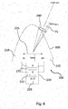
- a fine direction finding is carried out, which determines an exact position of an exemplary pixel 75 within the antenna width at half maximum 240 .
- a phase monopulse method can be used for this purpose, for example, in which one or more transmission pulse(s) are transmitted and at least two reception antennas 210, 220 receive reflected reception signals in order to determine an exact angle AziMopu of the pixel 75 as a fine bearing from a phase difference in the reflected reception signals.
- the line of sight (rough bearing AziBeam) itself is also known.
- the radar signals can be compensated for using the known relative speed v and provided as a compensated representation 150 of the radar signals.
- the radar beam is radiated with a beam width 240 in an azimuth angle AziBeam and can be swiveled with a swivel angle of approximately 40 degrees maximum (or in a range of 30 to 50 degrees measured from the vehicle velocity vector v).
- the received radar signals are analyzed for each beam angle AziBeam and can be displayed in a range Doppler matrix, so that the spatial area covered includes a large number of pixels 75, each of which belongs to a distance range (range gate) and a Doppler range (Doppler gate ) belong and in their entirety form the range Doppler matrix.
- the Doppler range corresponds to the Doppler shift (e.g. frequency shift due to relative movement) for the respective pixel.
- the received signals should more or less form a frequency line in the range Doppler matrix in the forward direction if there is no turbulence.
- a broadening of this line can have various causes and exemplary embodiments compensate for weather-independent effects.
- FIG. 3 shows further details for performing the fine bearing to determine the azimuth angle AziMopu.
- 3 shows a front part of the aircraft 300 with the radar system 200.
- the radar system 200 comprises a first antenna 210 (eg a left antenna AL) and a second antenna 220 (eg right antenna AR), which are spaced apart by a base width 225 from one another.
- Radar system 200 also includes an evaluation unit 230.
- Evaluation unit 230 includes a device 231 for determining differences and a device 232 for summation, which are designed to form sums/differences between the received signals from first antenna 210 and second antenna 220.
- a detection device 233 of the evaluation unit 230 for example, a ratio can be formed from the difference signal and the sum signal, from which the fine bearing angle AziMopu for the pixel 75 can be determined or can be determined by simple mathematical transformations.
- the Doppler effect can be determined based on the intrinsic motion and the position of each pixel in the range Doppler matrix can thus be changed (since the Doppler value changes) and thus compensated (in the respective Doppler value, the weather-independent component is subtracted out). As a result, ideally only a Doppler broadening of the line caused by the weather will remain.
- azi AziBeam + AziMopu , where AziBeam is the angle according to coarse bearing and AziMopu is the correction according to fine bearing.
- fd DGcompensated fd DG ⁇ fd DGVown .
- Azi AlphaBeam + AziMopu phi Half of the phase between the right and left channels or phases between the total antenna center (between the channels) and the individual antenna center [0.90] D doppler [0,prf] [0.3000] DG Doppler gate DGB width Wide Doppler gate 46.875 each (width) DGMax Maximum DG DG Dimension RD Matrix R range [0.12000] RG range gate RGBwidth 150 each (width) RGMax maximum evaluated RG RG Dimension RD Matrix v Velocity amount, e.g.
- errors that occur are compensated for.
- This error estimate provides a tolerance range of e.g. +/- 0.34 degrees for the values as listed in Table 1.
- each Doppler gate has an exemplary frequency range of 46.875 Hz, with the maximum representing the Doppler shift due to the relative movement between the flying object and the rainy area, and the broadening being a measure of this , how strong turbulences are in the respective spatial area, which partly strengthen or weaken the Doppler shift.
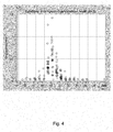
- the weather-independent contributions to Doppler broadening were calculated according to exemplary embodiments.
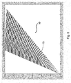
- FIG. 12 shows an exemplary top view (azimuth plane) of the individual pixels in the detected angular spatial region 240 that is illuminated by the antenna (eg +/-3 dB sensitivity range of the antenna).
- the approach geometry can be off 2 and the underlying exemplary values can be taken from Table 1.
- each box is a pixel that is correlated to a particular range and azimuth angle and for which the Doppler shift is determined.
- the number of Doppler cells in the antenna pattern corresponds to the Doppler spread caused by the radar's own movement in the beam. It is similar to a synthetic aperture radar (SAR) system, however it also includes scenarios where weather areas with added velocity vectors of great variability are present.
- SAR synthetic aperture radar
- FIG. 6 shows an example of a range-doppler matrix 50, as is used in exemplary embodiments as a representation 50 of the radar signals.
- the grid pattern of pixels is now not in plan view (as in figure 5 ) but directly related in the range and doppler domains.
- the distance ranges (range gates) are shown on the vertical axis and the Doppler ranges (Doppler gates) are shown on the horizontal axis, with 9 Doppler gates each having a frequency bandwidth of approximately 46 Hz being used, for example.
- the exemplary pixel 75 again has a range value of 32 and a Doppler value of 19. For the example used, this means that the region of space to which the pixel is 32 range gates each 150 m wide (ie approx. 4.8 km distance) and a Doppler shift of 19 Doppler gates of about 46 Hz each (ie a Doppler shift of 874 Hz by way of example), the exemplary radar wavelength being 3 cm.
- the method can include all functionalities as have been described for the device or the weather radar system.
- the critical 2-3 Doppler gates mean that deviation angles of 3 to 4.5 degrees would be allowed. In this area, weather-related broadening could still be reliably detected.
- the compensation according to exemplary embodiments leads to an improvement by a factor of 4 (see above), so that offset angles of 12 to 18 degrees would be permitted with compensation (because of the linearity). This is a significant increase in the deviation angle from the velocity vector v, at which it should be possible to reliably detect a critical weather situation. This also improves the overall success of evasive maneuvers.
- the Doppler expansions due to the turbulent weather can therefore be measured even at higher deviation angles and evasive maneuvers can be flown in good time before the "weather" in order not to damage the exemplary drone 300 flying autonomously.
- the method enables smaller on-board radar systems (e.g. 25 cm antenna size) to perform in the detection of turbulence, which would require an antenna size in the range of more than 50 cm for conventional on-board weather radar systems without monopulse capability.
Landscapes
- Engineering & Computer Science (AREA)
- Radar, Positioning & Navigation (AREA)
- Remote Sensing (AREA)
- Physics & Mathematics (AREA)
- Computer Networks & Wireless Communication (AREA)
- General Physics & Mathematics (AREA)
- Aviation & Aerospace Engineering (AREA)
- Electromagnetism (AREA)
- Radar Systems Or Details Thereof (AREA)
Priority Applications (2)
| Application Number | Priority Date | Filing Date | Title |
|---|---|---|---|
| EP20184520.3A EP3936892A1 (fr) | 2020-07-07 | 2020-07-07 | Dispositif et procédé de compensation des élargissements doppler |
| US17/368,873 US11747460B2 (en) | 2020-07-07 | 2021-07-07 | Apparatus and method for compensating for doppler expansions |
Applications Claiming Priority (1)
| Application Number | Priority Date | Filing Date | Title |
|---|---|---|---|
| EP20184520.3A EP3936892A1 (fr) | 2020-07-07 | 2020-07-07 | Dispositif et procédé de compensation des élargissements doppler |
Publications (1)
| Publication Number | Publication Date |
|---|---|
| EP3936892A1 true EP3936892A1 (fr) | 2022-01-12 |
Family
ID=71523072
Family Applications (1)
| Application Number | Title | Priority Date | Filing Date |
|---|---|---|---|
| EP20184520.3A Pending EP3936892A1 (fr) | 2020-07-07 | 2020-07-07 | Dispositif et procédé de compensation des élargissements doppler |
Country Status (2)
| Country | Link |
|---|---|
| US (1) | US11747460B2 (fr) |
| EP (1) | EP3936892A1 (fr) |
Families Citing this family (1)
| Publication number | Priority date | Publication date | Assignee | Title |
|---|---|---|---|---|
| CN120428192B (zh) * | 2025-07-09 | 2025-09-30 | 安徽迪万科技有限公司 | 一种基于深度学习的目标识别及定位方法 |
Citations (1)
| Publication number | Priority date | Publication date | Assignee | Title |
|---|---|---|---|---|
| CN106054195A (zh) * | 2016-05-31 | 2016-10-26 | 中国民航大学 | 基于空时最优处理器的湍流谱宽估计方法 |
Family Cites Families (3)
| Publication number | Priority date | Publication date | Assignee | Title |
|---|---|---|---|---|
| US20050179579A1 (en) * | 2003-12-29 | 2005-08-18 | Pinder Shane D. | Radar receiver motion compensation system and method |
| US10613212B2 (en) * | 2017-08-14 | 2020-04-07 | Oculii Corp. | Systems and methods for doppler-enhanced radar tracking |
| WO2021177956A1 (fr) * | 2020-03-04 | 2021-09-10 | Google Llc | Système radar basé sur un dispositif intelligent réalisant une détection à portée proximale |
-
2020
- 2020-07-07 EP EP20184520.3A patent/EP3936892A1/fr active Pending
-
2021
- 2021-07-07 US US17/368,873 patent/US11747460B2/en active Active
Patent Citations (1)
| Publication number | Priority date | Publication date | Assignee | Title |
|---|---|---|---|---|
| CN106054195A (zh) * | 2016-05-31 | 2016-10-26 | 中国民航大学 | 基于空时最优处理器的湍流谱宽估计方法 |
Non-Patent Citations (1)
| Title |
|---|
| YADIN E: "A performance evaluation model for a two port interferometer SAR-MTI", THE PROCEEDINGS OF THE 1996 IEEE NATIONAL RADAR CONFERENCE : HELD AT THE UNIVERSITY OF MICHIGAN, ANN ARBOR, MICHIGAN, 13 - 16 MAY, 1996, IEEE, NEW YORK, NY, USA, 13 May 1996 (1996-05-13), pages 261 - 266, XP010164763, ISBN: 978-0-7803-3145-7, DOI: 10.1109/NRC.1996.510691 * |
Also Published As
| Publication number | Publication date |
|---|---|
| US20220011424A1 (en) | 2022-01-13 |
| US11747460B2 (en) | 2023-09-05 |
Similar Documents
| Publication | Publication Date | Title |
|---|---|---|
| EP3847470B1 (fr) | Procédé de détection d'erreurs de mesures angulaires dans un capteur de radar | |
| EP3803454B1 (fr) | Procédé radar à ouverture synthetique et dispositif radar à ouverture synthetique | |
| DE60302379T2 (de) | Radarverarbeitungssystem und Verfahren zur Erkennung und Überwachung von Zielen | |
| EP2247960B1 (fr) | Dispositif et procédé d'évaluation de direction améliorée et de décodage au moyen de signaux radar secondaires | |
| EP2294442B1 (fr) | Procédé et dispositif de détermination passive de paramètres cibles | |
| DE69026583T2 (de) | Radar mit synthetischer Apertur und Strahlkeulenschärfungsfähigkeit in der Richtung der Fahrt | |
| DE112010005194T5 (de) | Hinderniserfassungsvorrichtung | |
| EP3060942B1 (fr) | Procédé pour la détermination de la disposition d'au moins deux capteurs et réseaux de capteurs | |
| DE102018202864A1 (de) | Verfahren und System für Synthetische-Apertur-Radarsignalverarbeitung | |
| DE102006009121A1 (de) | Verfahren zur Verarbeitung und Darstellung von mittels Synthetik-Apertur-Radarsystemen (SAR) gewonnen Bodenbildern | |
| DE4332590C2 (de) | Flugzeuggetragenes SAR-System zur Bestimmung einer Gelände-Topographie | |
| DE102019114723A1 (de) | Abschwächen von schwingungen in einem radarsystem auf einer beweglichen plattform | |
| DE102013203574A1 (de) | Verfahren zur Kompensation von Winkelmessfehlern | |
| DE69307551T2 (de) | Doppler wetterradar zum erfassen von windscherungen im flug | |
| DE19730306C2 (de) | Verfahren zur Synchronisation von Navigationsmeßdaten mit SAR-Radardaten und Einrichtung zur Durchführung dieses Verfahrens | |
| EP3465263B1 (fr) | Procédé de production d'une image d'observation terrestre d'une région au moyen d'un radar à synthèse d'ouverture | |
| EP1515159A1 (fr) | Méthode pour réduire le centroide doppler pour des systèmes radar coherent à impulsion | |
| EP3584600B1 (fr) | Recherche coordonnée d'un espace aérien | |
| EP3936892A1 (fr) | Dispositif et procédé de compensation des élargissements doppler | |
| EP4063891B1 (fr) | Système et procédé de détection et de localisation d'une source de signal | |
| DE102019114694B4 (de) | Radarsystem und Verfahren zum Konfigurieren eines Radarsystems | |
| DE3938340C2 (de) | Verfahren und Einrichtung zur Funkortung durch Überwachungs-Sekundärradar | |
| DE102019106293B3 (de) | Verfahren zum Detektieren eines Flugobjekts und Passives Radardetektionssystem zum Detektieren eines Flugobjekts | |
| DE102013013123B4 (de) | Verfahren und Vorrichtung zur Ortung von Funkstationen mittels Doppler-Effekt an Bord von fliegenden Plattformen | |
| DE102016224962B3 (de) | Synthetik-Apertur-Radarverfahren und Synthetik-Apertur-Radarsystem |
Legal Events
| Date | Code | Title | Description |
|---|---|---|---|
| PUAI | Public reference made under article 153(3) epc to a published international application that has entered the european phase |
Free format text: ORIGINAL CODE: 0009012 |
|
| STAA | Information on the status of an ep patent application or granted ep patent |
Free format text: STATUS: THE APPLICATION HAS BEEN PUBLISHED |
|
| AK | Designated contracting states |
Kind code of ref document: A1 Designated state(s): AL AT BE BG CH CY CZ DE DK EE ES FI FR GB GR HR HU IE IS IT LI LT LU LV MC MK MT NL NO PL PT RO RS SE SI SK SM TR |
|
| B565 | Issuance of search results under rule 164(2) epc |
Effective date: 20201216 |
|
| STAA | Information on the status of an ep patent application or granted ep patent |
Free format text: STATUS: REQUEST FOR EXAMINATION WAS MADE |
|
| 17P | Request for examination filed |
Effective date: 20220711 |
|
| RBV | Designated contracting states (corrected) |
Designated state(s): AL AT BE BG CH CY CZ DE DK EE ES FI FR GB GR HR HU IE IS IT LI LT LU LV MC MK MT NL NO PL PT RO RS SE SI SK SM TR |
|
| STAA | Information on the status of an ep patent application or granted ep patent |
Free format text: STATUS: EXAMINATION IS IN PROGRESS |
|
| 17Q | First examination report despatched |
Effective date: 20240304 |