EP3937312A1 - Ensemble de couvercle pour un appareil électrique - Google Patents
Ensemble de couvercle pour un appareil électrique Download PDFInfo
- Publication number
- EP3937312A1 EP3937312A1 EP20305765.8A EP20305765A EP3937312A1 EP 3937312 A1 EP3937312 A1 EP 3937312A1 EP 20305765 A EP20305765 A EP 20305765A EP 3937312 A1 EP3937312 A1 EP 3937312A1
- Authority
- EP
- European Patent Office
- Prior art keywords
- cover assembly
- separable part
- electrical
- sized
- conductor
- Prior art date
- Legal status (The legal status is an assumption and is not a legal conclusion. Google has not performed a legal analysis and makes no representation as to the accuracy of the status listed.)
- Granted
Links
Images


Classifications
-
- H—ELECTRICITY
- H01—ELECTRIC ELEMENTS
- H01R—ELECTRICALLY-CONDUCTIVE CONNECTIONS; STRUCTURAL ASSOCIATIONS OF A PLURALITY OF MUTUALLY-INSULATED ELECTRICAL CONNECTING ELEMENTS; COUPLING DEVICES; CURRENT COLLECTORS
- H01R13/00—Details of coupling devices of the kinds covered by groups H01R12/70 or H01R24/00 - H01R33/00
- H01R13/44—Means for preventing access to live contacts
- H01R13/447—Shutter or cover plate
-
- H—ELECTRICITY
- H01—ELECTRIC ELEMENTS
- H01R—ELECTRICALLY-CONDUCTIVE CONNECTIONS; STRUCTURAL ASSOCIATIONS OF A PLURALITY OF MUTUALLY-INSULATED ELECTRICAL CONNECTING ELEMENTS; COUPLING DEVICES; CURRENT COLLECTORS
- H01R9/00—Structural associations of a plurality of mutually-insulated electrical connecting elements, e.g. terminal strips or terminal blocks; Terminals or binding posts mounted upon a base or in a case; Bases therefor
- H01R9/22—Bases, e.g. strip, block, panel
- H01R9/24—Terminal blocks
- H01R9/26—Clip-on terminal blocks for side-by-side rail- or strip-mounting
- H01R9/2625—Clip-on terminal blocks for side-by-side rail- or strip-mounting with built-in electrical component
- H01R9/2666—Clip-on terminal blocks for side-by-side rail- or strip-mounting with built-in electrical component with built-in test-points
-
- H—ELECTRICITY
- H01—ELECTRIC ELEMENTS
- H01H—ELECTRIC SWITCHES; RELAYS; SELECTORS; EMERGENCY PROTECTIVE DEVICES
- H01H9/00—Details of switching devices, not covered by groups H01H1/00 - H01H7/00
- H01H9/02—Bases, casings, or covers
- H01H9/0264—Protective covers for terminals
-
- H—ELECTRICITY
- H01—ELECTRIC ELEMENTS
- H01R—ELECTRICALLY-CONDUCTIVE CONNECTIONS; STRUCTURAL ASSOCIATIONS OF A PLURALITY OF MUTUALLY-INSULATED ELECTRICAL CONNECTING ELEMENTS; COUPLING DEVICES; CURRENT COLLECTORS
- H01R2201/00—Connectors or connections adapted for particular applications
- H01R2201/20—Connectors or connections adapted for particular applications for testing or measuring purposes
Definitions
- the present invention concerns a cover assembly for an electrical apparatus having a plurality of conductor terminals.
- Such an electrical apparatus can be for example a terminal block dedicated to test an electrical installation.
- This kind of electrical apparatus generally has a front face presenting testing terminals that are accessible to an operator for various controls as calibration, value measuring, etc.
- the plurality of conductor terminals are generally located on a rear face opposed to the front face.
- the conductor terminals are linked to the electrical installation with several conductors.
- the conductors can have different diameters, which implies that the terminals are designed to receive the biggest admissible diameter.
- the present invention aims to solve all or some of the disadvantages mentioned above.
- the present invention relates to a cover assembly for an electrical apparatus configured for covering a plurality of conductor terminals of the electrical apparatus, the cover assembly having for each conductor terminal a first separable part and a second separable part configured to be engender a first sized terminal opening when the first separable part is removed and to engender a second sized terminal opening when the first separable part and the second separable part are removed.
- the cover assembly has a plurality of first separable parts and a plurality of second separable parts.
- Each first separable part is arranged to be removed from the cover assembly to create a first sized terminal opening for the insertion of a correspondingly sized conductor.
- a bigger sized conductor can be inserted.
- the cover assembly enables to protect the plurality of conductor terminals of the electrical apparatus. When only some of the conductor terminals are used, the cover assembly enables to create different sized terminal openings where necessary and sized according to the plugged conductors.
- the cover assembly has then a safety purpose as it protects each terminal of the electrical apparatus that are plugged or unplugged. In particular, it prevents a used to touch a conductive part.
- the first separable part and the second separable part are configured to prevent access to the corresponding terminal conductor from the exterior at least according to an IP20 index.
- each first separable part and second separable part are covering the corresponding conductor terminal.
- the cover assembly then enables to prevent a user to touch a conductive part of the electrical apparatus.
- the first sized terminal opening and the second sized terminal opening respect at least an IP20 index.
- the cover assembly comprises at least one removable shutter on which are located the first separable parts and the second separable parts.
- This provision enables to easily remove the necessary first separable parts and second separable parts from the cover assembly as the removable shutter can be removed from the cover assembly and thus from the electrical apparatus.
- the or each removable shutter comprises a grip.
- said grip corresponds to a protrusion designed to be seized by hand.
- the grip presents a through hole. This provision facilitates the removal by hand or with the help of a tool.
- the cover assembly comprises a body configured to be clipped on the electrical apparatus, the body comprising at least one insertion slot for receiving the at least one removable shutter.
- the body remains on the electrical apparatus while removing a separable part.
- the body is provided with at least one snap-in element to cooperate with a complementary snap-in element of the at least one removable shutter.
- the snap-in element corresponds to at least one hole and the complementary snap-in element corresponds to an at least one hook or vice versa.
- the cover assembly comprises two removable shutters located on opposed faces the cover assembly.
- the cover assembly is adapted to cooperate with a rear face of the electrical apparatus, the electrical apparatus being provided with two parallel rows of conductor terminals configured for plugging conductors according to two opposed directions transversally to the rows.
- the or each removable shutter comprises a plurality of strips, each strip comprising a corresponding first separable part and second separable part.
- the first separable part and the second separable part are adjacent fractions of the strip, the first separable part constituting an extremity of the strip.
- the removal of the first separable part reduces the length of the strip to engender a first sized terminal opening in the cover assembly.
- the length of the strip can be further reduced by removing the second separable part.
- the first separable part and the second separable part are pre-cut.
- a first groove is located on the strip between the first separable part and the second separable part.
- a second groove is located on the strip to separate the second separable part or both separable parts from the strip.
- the cover assembly further has at least one eyelet configured for receiving a seal.
- the at least one eyelet is included in the body.
- the or each eyelet is located in proximity to a corresponding through hole of the removable shutter so as to enable to seal together the removable shutter and the body.
- the cover assembly further has at least one reference orifice configured to be facing a corresponding marking of the electrical apparatus.
- the at least one reference orifice is included in the body.
- the cover assembly has a plurality of reference orifices, each reference orifice corresponding to conductor terminal.
- the plurality of reference orifices are aligned according two lines, each line being parallel and located next to a corresponding row of conductor terminal.
- the at least one reference orifice and/or the at least one insertion slot are located on a rear part of the cover assembly extending transversally to the at least one removable shutter.
- the eyelet is configured to enable an insertion of a cable of a seal transversally to the extension direction of the rear part of cover assembly.
- the present invention also concerns an electrical testing assembly comprising the electrical apparatus and a cover assembly as detailed above, wherein the electrical apparatus has a front face presenting testing terminals and a rear face opposed to the front face and configured to receive the cover assembly.
- the plurality of conductor terminals are located on the rear face.
- the markings are located on the rear face.
- the at least one removable shutter are extending transversally to the front face and the rear face.
- the electrical testing assembly further comprises a first sized electrical conductor plugged in a conductor terminal of the electrical apparatus, wherein the corresponding first separable part is removed and the second separable part is present, the space engendered between the first sized terminal opening and the first sized electrical conductor being defined with respect to at least an IP20 index.
- the electrical testing assembly further comprises a second sized electrical conductor plugged in a conductor terminal or alternatively two first sized electrical conductors plugged in said conductor terminal, wherein the corresponding first separable part and the second separable part are removed, the space engendered between the second sized terminal opening and the second sized electrical conductor or alternatively two the first sized electrical conductors being defined with respect to at least an IP20 index.
- the removal the first separable part and the second separable part enable to maintain a protection for the user.
- the electrical apparatus is a terminal block dedicated for testing an electrical installation.
- the terminal block is dedicated for calibration, value measuring as current or voltage or other electrical values.
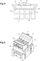
- a cover assembly 1 for an electrical apparatus 3 is configured for covering a plurality of conductor terminals 5 of the electrical apparatus 3.
- the cover assembly 1 has, for each conductor terminal 5, a first separable part 7 and a second separable part 9 configured to be engender a first sized terminal opening 11 when the first separable part 7 is removed and to engender a second sized terminal opening 13 when the first separable part 7 and the second separable part 9 are removed.
- the cover assembly 1 has a plurality of first separable parts 7 and a plurality of second separable parts 9.
- Each first separable part 7 is arranged to be removed from the cover assembly 1 to create a first sized terminal opening 11 for the insertion of a correspondingly sized conductor.
- a bigger sized conductor can be inserted.
- the first separable part 7 and the second separable part 9 are configured to prevent access to the corresponding terminal conductor 5 from the exterior at least according to an IP20 index.
- the first sized terminal opening 11 and the second sized terminal opening 13 respect at least an IP20 index.
- the cover assembly 1 comprises at least one removable shutter 15 on which are located the first separable parts 7 and the second separable parts 9.
- the removable shutter 15 comprises a grip 17.
- Said grip 17 corresponds to a protrusion designed to be seized by hand.
- the grip 17 presents a through hole 19.
- the cover assembly 1 comprises a body 21 configured to be clipped on the electrical apparatus 3, the body 21 comprising at least one insertion slot 23 for receiving the at least one removable shutter 15.
- the body 21 remains on the electrical apparatus 3 while removing a separable part.
- the body 21 is provided with at least one snap-in element 25 to cooperate with a complementary snap-in element 27 of the at least one removable shutter 15.
- the snap-in element 25 corresponds to at least one hole and the complementary snap-in element 27 corresponds to an at least one hook.
- the cover assembly 1 comprises two removable shutters 15 located on opposed faces the cover assembly 1.
- the cover assembly 1 is adapted to cooperate with a rear face 29 of the electrical apparatus 3, the electrical apparatus 3 being provided with two parallel rows 31 of conductor terminals 4 configured for plugging conductors according to two opposed directions transversally to the rows 31.
- each removable shutter 15 comprises a plurality of strips 33, each strip 33 comprising a corresponding first separable part 7 and second separable part 9.
- the first separable part 7 and the second separable part 9 are adjacent fractions of the strip 33, the first separable part 7 constituting an extremity of the strip 33.
- the removal of the first separable part 7 reduces the length of the strip 33 to engender the first sized terminal opening 11 in the cover assembly 1.
- the length of the strip 33 can be further reduced by removing the second separable part 9.
- first separable part 7 and the second separable part 9 are pre-cut.
- a first groove 35 is located on the strip 33 between the first separable part 7 and the second separable part 9.
- a second groove 37 is located on the strip 33 to separate the second separable part 9 or both separable parts from the strip 33.
- the cover assembly 1 further has at least one eyelet 39 configured for receiving a seal.
- the at least one eyelet 39 is included in the body 21. Said eyelet 39 is located in proximity to a corresponding through hole 19 of a removable shutter 15 so as to enable to seal together the removable shutter 15 and the body 21.
- the cover assembly 1 further has at least one reference orifice 41 configured to be facing a corresponding marking of the electrical apparatus 3.
- the at least one reference orifice 41 is included in the body 21.
- the cover assembly 1 has a plurality of reference orifices 41, each reference orifice 41 corresponding to conductor terminal 5.
- the plurality of reference orifices 39 are aligned according two lines, each line being parallel and located next to a corresponding row 31 of conductor terminal 5.
- the at least one reference orifice 39 and/or the at least one insertion slot 23 are located on a rear part 43 of the cover assembly 1 extending transversally to the at least one removable shutter 15.
- the eyelet 39 is configured to enable an insertion of a cable of a seal transversally to the extension direction of the rear part 43 of cover assembly 1.
- An electrical testing assembly 45 comprising the electrical apparatus 3 and a cover assembly 1, wherein the electrical apparatus 3 has a front face 47 presenting testing terminals and said rear face 29 opposed to the front face 47 and configured to receive the cover assembly 1.
- the plurality of conductor terminals 5 are located on the rear face 29.
- the markings are located on the rear face 29.
- the at least one removable shutter 15 are extending transversally to the front face 47 and the rear face 29.
- the electrical testing assembly 45 further comprises a first sized electrical conductor 49 plugged in a conductor terminal 5 of the electrical apparatus 3 wherein the corresponding first separable part 7 is removed and the second separable part 9 is present, the space engendered between the first sized terminal opening 11 and the first sized electrical conductor 49 being defined with respect to at least an IP20 index.
- the electrical testing assembly further comprising a second sized electrical conductor 51 plugged in a conductor terminal 5 or alternatively two first sized electrical conductors plugged in said conductor terminal 5, wherein the corresponding first separable part 7 and the second separable part 9 are removed, the space engendered between the second sized terminal opening 13 and the second sized electrical conductor 51 or alternatively two the first sized electrical conductors 49 being defined with respect to at least an IP20 index.
- the electrical apparatus 3 is here a terminal block dedicated for testing an electrical installation.
- the terminal block is for example dedicated for calibration, value measuring as current or voltage or other electrical values.
- the cover assembly 1 as described above enables to protect the plurality of conductor terminals 5 of the electrical apparatus 3. When only some of the conductor terminals 5 are used, the cover assembly 1 enables to create different sized terminal openings where necessary and sized according to the plugged conductors.
- the cover assembly 1 has then a safety purpose as it protects each conductor terminal 5 of the electrical apparatus 3 that are plugged or unplugged. In particular, it prevents a used to touch a conductive part.
- the removable shutters 15 enable to easily remove the necessary first separable parts 7 and second separable parts 9 from the cover assembly 1 as the removable shutters 15 can be removed from the cover assembly 1 and thus from the electrical apparatus 3.
Landscapes
- Connector Housings Or Holding Contact Members (AREA)
Priority Applications (1)
| Application Number | Priority Date | Filing Date | Title |
|---|---|---|---|
| EP20305765.8A EP3937312B1 (fr) | 2020-07-06 | 2020-07-06 | Ensemble de couvercle pour un appareil électrique |
Applications Claiming Priority (1)
| Application Number | Priority Date | Filing Date | Title |
|---|---|---|---|
| EP20305765.8A EP3937312B1 (fr) | 2020-07-06 | 2020-07-06 | Ensemble de couvercle pour un appareil électrique |
Publications (2)
| Publication Number | Publication Date |
|---|---|
| EP3937312A1 true EP3937312A1 (fr) | 2022-01-12 |
| EP3937312B1 EP3937312B1 (fr) | 2025-08-20 |
Family
ID=71738078
Family Applications (1)
| Application Number | Title | Priority Date | Filing Date |
|---|---|---|---|
| EP20305765.8A Active EP3937312B1 (fr) | 2020-07-06 | 2020-07-06 | Ensemble de couvercle pour un appareil électrique |
Country Status (1)
| Country | Link |
|---|---|
| EP (1) | EP3937312B1 (fr) |
Citations (3)
| Publication number | Priority date | Publication date | Assignee | Title |
|---|---|---|---|---|
| FR2602948A1 (fr) * | 1986-08-13 | 1988-02-19 | Merlin Gerin | Boitier isolant pour appareillage electrique multipolaire |
| EP1069578A1 (fr) * | 1999-07-13 | 2001-01-17 | Power Controls Iberica S.A. | Dispositif de protection des bornes pour appareillage électrique basse tension |
| US8698023B2 (en) * | 2010-07-29 | 2014-04-15 | Siemens Aktiengesellschaft | Electrical switch |
-
2020
- 2020-07-06 EP EP20305765.8A patent/EP3937312B1/fr active Active
Patent Citations (3)
| Publication number | Priority date | Publication date | Assignee | Title |
|---|---|---|---|---|
| FR2602948A1 (fr) * | 1986-08-13 | 1988-02-19 | Merlin Gerin | Boitier isolant pour appareillage electrique multipolaire |
| EP1069578A1 (fr) * | 1999-07-13 | 2001-01-17 | Power Controls Iberica S.A. | Dispositif de protection des bornes pour appareillage électrique basse tension |
| US8698023B2 (en) * | 2010-07-29 | 2014-04-15 | Siemens Aktiengesellschaft | Electrical switch |
Also Published As
| Publication number | Publication date |
|---|---|
| EP3937312B1 (fr) | 2025-08-20 |
Similar Documents
| Publication | Publication Date | Title |
|---|---|---|
| US6932624B1 (en) | Modular signal and power connection device | |
| US7766689B2 (en) | Plug adapter for an electrical switching device | |
| JP6583323B2 (ja) | 配線用接続器具、及び電気機器 | |
| CA2621098A1 (fr) | Raccords de fils pour limiteurs de surtension et autres composants electriques | |
| DK165719B (da) | Klemliste for kabelledere isaer i telefonkabler | |
| PL183079B1 (pl) | Sposób przyłączania łączówki zaciskowej, izolującej lub łączącej i łączówka zaciskowa, izolująca lub łącząca | |
| HUP0800698A2 (en) | Cross connect terminal block | |
| EP2950398B1 (fr) | Systeme et procede d'identification de connexions dans une enceinte industrielle | |
| EP3937312B1 (fr) | Ensemble de couvercle pour un appareil électrique | |
| KR101850445B1 (ko) | 방수 커넥터 | |
| KR101869545B1 (ko) | 방수 커넥터 | |
| US11309654B2 (en) | Field device with electronic module including cover | |
| EP3477779B1 (fr) | Systeme comprenant une borne à virole et un bornier de connexion et équipement électrique comprenant un tel système | |
| EP0849835A2 (fr) | Connecteurs électriques comportant des éléments de fixation | |
| US20240243490A1 (en) | Plug connector having a bridging function | |
| KR101869540B1 (ko) | 방수 커넥터 | |
| US4971572A (en) | Electrical connector | |
| US20140342597A1 (en) | Compliant multi-connector block device | |
| GB2323221A (en) | Electrical connectors and connecting parts therefor | |
| JP7482832B2 (ja) | より線接続治具 | |
| ITTO940251A1 (it) | Basetta di presa di corrente | |
| WO2010032104A1 (fr) | Dispositif de câblage | |
| KR101869542B1 (ko) | 방수 커넥터 | |
| JP2017207411A (ja) | 試験用ターミナル | |
| JP5224578B2 (ja) | コンセント装置 |
Legal Events
| Date | Code | Title | Description |
|---|---|---|---|
| PUAI | Public reference made under article 153(3) epc to a published international application that has entered the european phase |
Free format text: ORIGINAL CODE: 0009012 |
|
| STAA | Information on the status of an ep patent application or granted ep patent |
Free format text: STATUS: THE APPLICATION HAS BEEN PUBLISHED |
|
| AK | Designated contracting states |
Kind code of ref document: A1 Designated state(s): AL AT BE BG CH CY CZ DE DK EE ES FI FR GB GR HR HU IE IS IT LI LT LU LV MC MK MT NL NO PL PT RO RS SE SI SK SM TR |
|
| B565 | Issuance of search results under rule 164(2) epc |
Effective date: 20201201 |
|
| STAA | Information on the status of an ep patent application or granted ep patent |
Free format text: STATUS: REQUEST FOR EXAMINATION WAS MADE |
|
| 17P | Request for examination filed |
Effective date: 20220328 |
|
| RBV | Designated contracting states (corrected) |
Designated state(s): AL AT BE BG CH CY CZ DE DK EE ES FI FR GB GR HR HU IE IS IT LI LT LU LV MC MK MT NL NO PL PT RO RS SE SI SK SM TR |
|
| STAA | Information on the status of an ep patent application or granted ep patent |
Free format text: STATUS: EXAMINATION IS IN PROGRESS |
|
| 17Q | First examination report despatched |
Effective date: 20231023 |
|
| RAP1 | Party data changed (applicant data changed or rights of an application transferred) |
Owner name: TE CONNECTIVITY SOLUTIONS GMBH |
|
| GRAP | Despatch of communication of intention to grant a patent |
Free format text: ORIGINAL CODE: EPIDOSNIGR1 |
|
| STAA | Information on the status of an ep patent application or granted ep patent |
Free format text: STATUS: GRANT OF PATENT IS INTENDED |
|
| INTG | Intention to grant announced |
Effective date: 20250327 |
|
| GRAS | Grant fee paid |
Free format text: ORIGINAL CODE: EPIDOSNIGR3 |
|
| GRAA | (expected) grant |
Free format text: ORIGINAL CODE: 0009210 |
|
| STAA | Information on the status of an ep patent application or granted ep patent |
Free format text: STATUS: THE PATENT HAS BEEN GRANTED |
|
| AK | Designated contracting states |
Kind code of ref document: B1 Designated state(s): AL AT BE BG CH CY CZ DE DK EE ES FI FR GB GR HR HU IE IS IT LI LT LU LV MC MK MT NL NO PL PT RO RS SE SI SK SM TR |
|
| REG | Reference to a national code |
Ref country code: GB Ref legal event code: FG4D |
|
| REG | Reference to a national code |
Ref country code: CH Ref legal event code: EP |
|
| REG | Reference to a national code |
Ref country code: IE Ref legal event code: FG4D |
|
| REG | Reference to a national code |
Ref country code: DE Ref legal event code: R096 Ref document number: 602020056896 Country of ref document: DE |
|
| REG | Reference to a national code |
Ref country code: NL Ref legal event code: MP Effective date: 20250820 |
|
| PG25 | Lapsed in a contracting state [announced via postgrant information from national office to epo] |
Ref country code: IS Free format text: LAPSE BECAUSE OF FAILURE TO SUBMIT A TRANSLATION OF THE DESCRIPTION OR TO PAY THE FEE WITHIN THE PRESCRIBED TIME-LIMIT Effective date: 20251220 |
|
| PG25 | Lapsed in a contracting state [announced via postgrant information from national office to epo] |
Ref country code: NO Free format text: LAPSE BECAUSE OF FAILURE TO SUBMIT A TRANSLATION OF THE DESCRIPTION OR TO PAY THE FEE WITHIN THE PRESCRIBED TIME-LIMIT Effective date: 20251120 |
|
| REG | Reference to a national code |
Ref country code: LT Ref legal event code: MG9D |
|
| PG25 | Lapsed in a contracting state [announced via postgrant information from national office to epo] |
Ref country code: PT Free format text: LAPSE BECAUSE OF FAILURE TO SUBMIT A TRANSLATION OF THE DESCRIPTION OR TO PAY THE FEE WITHIN THE PRESCRIBED TIME-LIMIT Effective date: 20251222 |
|
| PG25 | Lapsed in a contracting state [announced via postgrant information from national office to epo] |
Ref country code: FI Free format text: LAPSE BECAUSE OF FAILURE TO SUBMIT A TRANSLATION OF THE DESCRIPTION OR TO PAY THE FEE WITHIN THE PRESCRIBED TIME-LIMIT Effective date: 20250820 |
|
| PG25 | Lapsed in a contracting state [announced via postgrant information from national office to epo] |
Ref country code: HR Free format text: LAPSE BECAUSE OF FAILURE TO SUBMIT A TRANSLATION OF THE DESCRIPTION OR TO PAY THE FEE WITHIN THE PRESCRIBED TIME-LIMIT Effective date: 20250820 Ref country code: NL Free format text: LAPSE BECAUSE OF FAILURE TO SUBMIT A TRANSLATION OF THE DESCRIPTION OR TO PAY THE FEE WITHIN THE PRESCRIBED TIME-LIMIT Effective date: 20250820 |
|
| PG25 | Lapsed in a contracting state [announced via postgrant information from national office to epo] |
Ref country code: GR Free format text: LAPSE BECAUSE OF FAILURE TO SUBMIT A TRANSLATION OF THE DESCRIPTION OR TO PAY THE FEE WITHIN THE PRESCRIBED TIME-LIMIT Effective date: 20251121 |
|
| PG25 | Lapsed in a contracting state [announced via postgrant information from national office to epo] |
Ref country code: SE Free format text: LAPSE BECAUSE OF FAILURE TO SUBMIT A TRANSLATION OF THE DESCRIPTION OR TO PAY THE FEE WITHIN THE PRESCRIBED TIME-LIMIT Effective date: 20250820 |
|
| PG25 | Lapsed in a contracting state [announced via postgrant information from national office to epo] |
Ref country code: LV Free format text: LAPSE BECAUSE OF FAILURE TO SUBMIT A TRANSLATION OF THE DESCRIPTION OR TO PAY THE FEE WITHIN THE PRESCRIBED TIME-LIMIT Effective date: 20250820 |
|
| PG25 | Lapsed in a contracting state [announced via postgrant information from national office to epo] |
Ref country code: BG Free format text: LAPSE BECAUSE OF FAILURE TO SUBMIT A TRANSLATION OF THE DESCRIPTION OR TO PAY THE FEE WITHIN THE PRESCRIBED TIME-LIMIT Effective date: 20250820 Ref country code: PL Free format text: LAPSE BECAUSE OF FAILURE TO SUBMIT A TRANSLATION OF THE DESCRIPTION OR TO PAY THE FEE WITHIN THE PRESCRIBED TIME-LIMIT Effective date: 20250820 |
|
| PG25 | Lapsed in a contracting state [announced via postgrant information from national office to epo] |
Ref country code: RS Free format text: LAPSE BECAUSE OF FAILURE TO SUBMIT A TRANSLATION OF THE DESCRIPTION OR TO PAY THE FEE WITHIN THE PRESCRIBED TIME-LIMIT Effective date: 20251120 |
|
| PG25 | Lapsed in a contracting state [announced via postgrant information from national office to epo] |
Ref country code: ES Free format text: LAPSE BECAUSE OF FAILURE TO SUBMIT A TRANSLATION OF THE DESCRIPTION OR TO PAY THE FEE WITHIN THE PRESCRIBED TIME-LIMIT Effective date: 20250820 |
|
| REG | Reference to a national code |
Ref country code: AT Ref legal event code: MK05 Ref document number: 1828386 Country of ref document: AT Kind code of ref document: T Effective date: 20250820 |
|
| PG25 | Lapsed in a contracting state [announced via postgrant information from national office to epo] |
Ref country code: SM Free format text: LAPSE BECAUSE OF FAILURE TO SUBMIT A TRANSLATION OF THE DESCRIPTION OR TO PAY THE FEE WITHIN THE PRESCRIBED TIME-LIMIT Effective date: 20250820 |
|
| PG25 | Lapsed in a contracting state [announced via postgrant information from national office to epo] |
Ref country code: DK Free format text: LAPSE BECAUSE OF FAILURE TO SUBMIT A TRANSLATION OF THE DESCRIPTION OR TO PAY THE FEE WITHIN THE PRESCRIBED TIME-LIMIT Effective date: 20250820 |
|
| PG25 | Lapsed in a contracting state [announced via postgrant information from national office to epo] |
Ref country code: AT Free format text: LAPSE BECAUSE OF FAILURE TO SUBMIT A TRANSLATION OF THE DESCRIPTION OR TO PAY THE FEE WITHIN THE PRESCRIBED TIME-LIMIT Effective date: 20250820 |
|
| PG25 | Lapsed in a contracting state [announced via postgrant information from national office to epo] |
Ref country code: IT Free format text: LAPSE BECAUSE OF FAILURE TO SUBMIT A TRANSLATION OF THE DESCRIPTION OR TO PAY THE FEE WITHIN THE PRESCRIBED TIME-LIMIT Effective date: 20250820 |
|
| PG25 | Lapsed in a contracting state [announced via postgrant information from national office to epo] |
Ref country code: CZ Free format text: LAPSE BECAUSE OF FAILURE TO SUBMIT A TRANSLATION OF THE DESCRIPTION OR TO PAY THE FEE WITHIN THE PRESCRIBED TIME-LIMIT Effective date: 20250820 |
|
| PG25 | Lapsed in a contracting state [announced via postgrant information from national office to epo] |
Ref country code: SK Free format text: LAPSE BECAUSE OF FAILURE TO SUBMIT A TRANSLATION OF THE DESCRIPTION OR TO PAY THE FEE WITHIN THE PRESCRIBED TIME-LIMIT Effective date: 20250820 Ref country code: EE Free format text: LAPSE BECAUSE OF FAILURE TO SUBMIT A TRANSLATION OF THE DESCRIPTION OR TO PAY THE FEE WITHIN THE PRESCRIBED TIME-LIMIT Effective date: 20250820 |
|
| REG | Reference to a national code |
Ref country code: DE Ref legal event code: R097 Ref document number: 602020056896 Country of ref document: DE |
|
| PLBE | No opposition filed within time limit |
Free format text: ORIGINAL CODE: 0009261 |
|
| STAA | Information on the status of an ep patent application or granted ep patent |
Free format text: STATUS: NO OPPOSITION FILED WITHIN TIME LIMIT |
|
| PG25 | Lapsed in a contracting state [announced via postgrant information from national office to epo] |
Ref country code: LT Free format text: LAPSE BECAUSE OF FAILURE TO SUBMIT A TRANSLATION OF THE DESCRIPTION OR TO PAY THE FEE WITHIN THE PRESCRIBED TIME-LIMIT Effective date: 20250820 |
|
| REG | Reference to a national code |
Ref country code: CH Ref legal event code: L10 Free format text: ST27 STATUS EVENT CODE: U-0-0-L10-L00 (AS PROVIDED BY THE NATIONAL OFFICE) Effective date: 20260701 |
|
| PGFP | Annual fee paid to national office [announced via postgrant information from national office to epo] |
Ref country code: GB Payment date: 20260608 Year of fee payment: 7 |
|
| PGFP | Annual fee paid to national office [announced via postgrant information from national office to epo] |
Ref country code: FR Payment date: 20260608 Year of fee payment: 7 |
|
| 26N | No opposition filed |
Effective date: 20260521 |