EP3937362A1 - Système de détection d'anomalie pour un réseau d'énergie solaire - Google Patents
Système de détection d'anomalie pour un réseau d'énergie solaire Download PDFInfo
- Publication number
- EP3937362A1 EP3937362A1 EP21183741.4A EP21183741A EP3937362A1 EP 3937362 A1 EP3937362 A1 EP 3937362A1 EP 21183741 A EP21183741 A EP 21183741A EP 3937362 A1 EP3937362 A1 EP 3937362A1
- Authority
- EP
- European Patent Office
- Prior art keywords
- power
- switch
- processor
- solar power
- signal
- Prior art date
- Legal status (The legal status is an assumption and is not a legal conclusion. Google has not performed a legal analysis and makes no representation as to the accuracy of the status listed.)
- Granted
Links
Images



Classifications
-
- H—ELECTRICITY
- H02—GENERATION; CONVERSION OR DISTRIBUTION OF ELECTRIC POWER
- H02S—GENERATION OF ELECTRIC POWER BY CONVERSION OF INFRARED RADIATION, VISIBLE LIGHT OR ULTRAVIOLET LIGHT, e.g. USING PHOTOVOLTAIC [PV] MODULES
- H02S50/00—Monitoring or testing of PV systems, e.g. load balancing or fault identification
- H02S50/10—Testing of PV devices, e.g. of PV modules or single PV cells
-
- H—ELECTRICITY
- H02—GENERATION; CONVERSION OR DISTRIBUTION OF ELECTRIC POWER
- H02H—EMERGENCY PROTECTIVE CIRCUIT ARRANGEMENTS
- H02H7/00—Emergency protective circuit arrangements specially adapted for specific types of electric machines or apparatus or for sectionalised protection of cable or line systems, and effecting automatic switching in the event of an undesired change from normal working conditions
- H02H7/10—Emergency protective circuit arrangements specially adapted for specific types of electric machines or apparatus or for sectionalised protection of cable or line systems, and effecting automatic switching in the event of an undesired change from normal working conditions for converters; for rectifiers
- H02H7/12—Emergency protective circuit arrangements specially adapted for specific types of electric machines or apparatus or for sectionalised protection of cable or line systems, and effecting automatic switching in the event of an undesired change from normal working conditions for converters; for rectifiers for static converters or rectifiers
- H02H7/122—Emergency protective circuit arrangements specially adapted for specific types of electric machines or apparatus or for sectionalised protection of cable or line systems, and effecting automatic switching in the event of an undesired change from normal working conditions for converters; for rectifiers for static converters or rectifiers for inverters, i.e. DC/AC converters
- H02H7/1227—Emergency protective circuit arrangements specially adapted for specific types of electric machines or apparatus or for sectionalised protection of cable or line systems, and effecting automatic switching in the event of an undesired change from normal working conditions for converters; for rectifiers for static converters or rectifiers for inverters, i.e. DC/AC converters responsive to abnormalities in the output circuit, e.g. short circuit
-
- H—ELECTRICITY
- H02—GENERATION; CONVERSION OR DISTRIBUTION OF ELECTRIC POWER
- H02S—GENERATION OF ELECTRIC POWER BY CONVERSION OF INFRARED RADIATION, VISIBLE LIGHT OR ULTRAVIOLET LIGHT, e.g. USING PHOTOVOLTAIC [PV] MODULES
- H02S50/00—Monitoring or testing of PV systems, e.g. load balancing or fault identification
-
- H—ELECTRICITY
- H02—GENERATION; CONVERSION OR DISTRIBUTION OF ELECTRIC POWER
- H02H—EMERGENCY PROTECTIVE CIRCUIT ARRANGEMENTS
- H02H7/00—Emergency protective circuit arrangements specially adapted for specific types of electric machines or apparatus or for sectionalised protection of cable or line systems, and effecting automatic switching in the event of an undesired change from normal working conditions
- H02H7/26—Sectionalised protection of cable or line systems, e.g. for disconnecting a section on which a short-circuit, earth fault, or arc discharge has occured
- H02H7/268—Sectionalised protection of cable or line systems, e.g. for disconnecting a section on which a short-circuit, earth fault, or arc discharge has occured for DC systems
-
- H—ELECTRICITY
- H02—GENERATION; CONVERSION OR DISTRIBUTION OF ELECTRIC POWER
- H02H—EMERGENCY PROTECTIVE CIRCUIT ARRANGEMENTS
- H02H1/00—Details of emergency protective circuit arrangements
- H02H1/0007—Details of emergency protective circuit arrangements concerning the detecting means
-
- H—ELECTRICITY
- H02—GENERATION; CONVERSION OR DISTRIBUTION OF ELECTRIC POWER
- H02H—EMERGENCY PROTECTIVE CIRCUIT ARRANGEMENTS
- H02H1/00—Details of emergency protective circuit arrangements
- H02H1/0092—Details of emergency protective circuit arrangements concerning the data processing means, e.g. expert systems, neural networks
-
- H—ELECTRICITY
- H02—GENERATION; CONVERSION OR DISTRIBUTION OF ELECTRIC POWER
- H02H—EMERGENCY PROTECTIVE CIRCUIT ARRANGEMENTS
- H02H7/00—Emergency protective circuit arrangements specially adapted for specific types of electric machines or apparatus or for sectionalised protection of cable or line systems, and effecting automatic switching in the event of an undesired change from normal working conditions
- H02H7/26—Sectionalised protection of cable or line systems, e.g. for disconnecting a section on which a short-circuit, earth fault, or arc discharge has occured
- H02H7/261—Sectionalised protection of cable or line systems, e.g. for disconnecting a section on which a short-circuit, earth fault, or arc discharge has occured involving signal transmission between at least two stations
- H02H7/262—Sectionalised protection of cable or line systems, e.g. for disconnecting a section on which a short-circuit, earth fault, or arc discharge has occured involving signal transmission between at least two stations involving transmissions of switching or blocking orders
-
- H—ELECTRICITY
- H02—GENERATION; CONVERSION OR DISTRIBUTION OF ELECTRIC POWER
- H02H—EMERGENCY PROTECTIVE CIRCUIT ARRANGEMENTS
- H02H7/00—Emergency protective circuit arrangements specially adapted for specific types of electric machines or apparatus or for sectionalised protection of cable or line systems, and effecting automatic switching in the event of an undesired change from normal working conditions
- H02H7/26—Sectionalised protection of cable or line systems, e.g. for disconnecting a section on which a short-circuit, earth fault, or arc discharge has occured
- H02H7/261—Sectionalised protection of cable or line systems, e.g. for disconnecting a section on which a short-circuit, earth fault, or arc discharge has occured involving signal transmission between at least two stations
- H02H7/263—Sectionalised protection of cable or line systems, e.g. for disconnecting a section on which a short-circuit, earth fault, or arc discharge has occured involving signal transmission between at least two stations involving transmissions of measured values
-
- H—ELECTRICITY
- H02—GENERATION; CONVERSION OR DISTRIBUTION OF ELECTRIC POWER
- H02M—APPARATUS FOR CONVERSION BETWEEN AC AND AC, BETWEEN AC AND DC, OR BETWEEN DC AND DC, AND FOR USE WITH MAINS OR SIMILAR POWER SUPPLY SYSTEMS; CONVERSION OF DC OR AC INPUT POWER INTO SURGE OUTPUT POWER; CONTROL OR REGULATION THEREOF
- H02M1/00—Details of apparatus for conversion
- H02M1/32—Means for protecting converters other than automatic disconnection
-
- H—ELECTRICITY
- H02—GENERATION; CONVERSION OR DISTRIBUTION OF ELECTRIC POWER
- H02S—GENERATION OF ELECTRIC POWER BY CONVERSION OF INFRARED RADIATION, VISIBLE LIGHT OR ULTRAVIOLET LIGHT, e.g. USING PHOTOVOLTAIC [PV] MODULES
- H02S40/00—Components or accessories in combination with PV modules, not provided for in groups H02S10/00 - H02S30/00
- H02S40/30—Electrical components
- H02S40/32—Electrical components comprising DC/AC inverter means associated with the PV module itself, e.g. AC modules
-
- H—ELECTRICITY
- H02—GENERATION; CONVERSION OR DISTRIBUTION OF ELECTRIC POWER
- H02J—ELECTRIC POWER NETWORKS; CIRCUIT ARRANGEMENTS OR SYSTEMS FOR SUPPLYING OR DISTRIBUTING ELECTRIC POWER; SYSTEMS FOR STORING ELECTRIC ENERGY
- H02J2101/00—Supply or distribution of decentralised, dispersed or local electric power generation
- H02J2101/20—Dispersed power generation using renewable energy sources
- H02J2101/22—Solar energy
- H02J2101/24—Photovoltaics
-
- Y—GENERAL TAGGING OF NEW TECHNOLOGICAL DEVELOPMENTS; GENERAL TAGGING OF CROSS-SECTIONAL TECHNOLOGIES SPANNING OVER SEVERAL SECTIONS OF THE IPC; TECHNICAL SUBJECTS COVERED BY FORMER USPC CROSS-REFERENCE ART COLLECTIONS [XRACs] AND DIGESTS
- Y02—TECHNOLOGIES OR APPLICATIONS FOR MITIGATION OR ADAPTATION AGAINST CLIMATE CHANGE
- Y02E—REDUCTION OF GREENHOUSE GAS [GHG] EMISSIONS, RELATED TO ENERGY GENERATION, TRANSMISSION OR DISTRIBUTION
- Y02E10/00—Energy generation through renewable energy sources
- Y02E10/50—Photovoltaic [PV] energy
-
- Y—GENERAL TAGGING OF NEW TECHNOLOGICAL DEVELOPMENTS; GENERAL TAGGING OF CROSS-SECTIONAL TECHNOLOGIES SPANNING OVER SEVERAL SECTIONS OF THE IPC; TECHNICAL SUBJECTS COVERED BY FORMER USPC CROSS-REFERENCE ART COLLECTIONS [XRACs] AND DIGESTS
- Y02—TECHNOLOGIES OR APPLICATIONS FOR MITIGATION OR ADAPTATION AGAINST CLIMATE CHANGE
- Y02E—REDUCTION OF GREENHOUSE GAS [GHG] EMISSIONS, RELATED TO ENERGY GENERATION, TRANSMISSION OR DISTRIBUTION
- Y02E10/00—Energy generation through renewable energy sources
- Y02E10/50—Photovoltaic [PV] energy
- Y02E10/56—Power conversion systems, e.g. maximum power point trackers
Definitions
- the disclosure relates to an abnormality detecting system for use with a solar power grid.
- Figure 1 illustrates a conventional solar power grid that includes a plurality of solar panel modules 11, a power inverter 12 that is electrically connected to the solar panel modules 11, a power distribution module 13 that is electrically connected to the power inverter 12, a plurality of first cable troughs 14 each disposed to cover a cable connecting a corresponding one of the solar panel modules 11 to the power inverter 12, and a second cable trough 15 disposed to cover a cable connecting the power inverter 12 to the power distribution module 13.
- the solar panel modules 11 are configured to convert sunlight into electricity, and to output the electricity to the power inverter 12 in the form of a direct current (DC) signal.
- the power inverter 12 is configured to receive the DC signal from the solar panel modules 11, and to convert the DC signal to a converted power signal in the form of an alternating current (AC) signal and to output the AC signal.
- the AC signal is then transmitted to the power distribution module 13 that is configured to distribute the AC signal to other parts of the conventional solar power grid.
- the cable used to connect the power inverter 12 to the power distribution module 13 and cables used to connect the power distribution module 13 to the other parts of the power grid are typically equipped with adequate power system protection mechanisms that assists in stabilizing the power grid when one or more components of the power grid become non-functional.
- One object of the disclosure is to provide an abnormality detecting system that can be installed between certain parts of a solar power grid to detect abnormality, and therefore perform necessary operations to prevent further damage to the solar power grid.
- the abnormality detecting system is for a solar power grid.
- the abnormality detecting system is to be disposed between a solar power module and a power inverter of the solar power grid.
- the solar power module includes a solar panel, and a first output node and a second output node that cooperatively output a solar power signal in a form of a direct current signal.
- the power inverter is electrically connected to the solar power module to receive the solar power signal therefrom and being configured to convert the solar power signal to a converted power signal in a form of an alternating current (AC) signal and to output the converted power signal.
- the abnormality detecting system includes a circuit protecting unit and a processor.
- the circuit protecting unit includes an input component including a first port and a second port that are configured to be electrically connected respectively to the first output node and the second output node, and being configured to receive the solar power signal from the solar power module through the first and second ports, a power switch electrically connected to the first port, an output component electrically connected between the power switch and the power inverter, a current detector electrically connected between the input component and the output component, and configured to measure an amount of electrical current flowing therethrough, and a control module electrically connected to the current detector and the power switch.
- the control module is capable of controlling the power switch to switch between an open circuit state in which the power switch disallows electrical current to flow therethrough, and a closed circuit state in which the power switch allows electrical current to flow therethrough.
- the processor is electrically connected to the control module, is configured to be electrically connected to the power inverter, and that is configured to:
- the terms “connected to”, “electrically connected to” may refer to a physical connection between two or more electronic devices or components via an electrical conductive material (which may be referred to as a direct electrical connection), via other electronic devices or components (which may be referred to as an indirect electrical connection) or wireless communications between two or more electronic devices or components using a wireless communication technique, such as a short-range wireless communication module supporting a short-range wireless communication network using a wireless technology of Bluetooth ® and/or Wi-Fi, etc., and a mobile communication module supporting telecommunication using Long-Term Evolution (LTE), a long range (LoRa) communication, the third generation (3G), fourth generation (4G), and/or fifth generation (5G) of wireless mobile telecommunications technology, fifth and/or the like.
- a wireless communication technique such as a short-range wireless communication module supporting a short-range wireless communication network using a wireless technology of Bluetooth ® and/or Wi-Fi, etc.
- LTE Long-Term Evolution
- 4G long range
- 5G fifth generation
- Figure 2 is a block diagram illustrating an abnormality detecting system used for a solar power grid 9 according to one embodiment of the disclosure.
- the solar power grid 9 includes a solar power module 91 and a power inverter 92.
- the solar power module 91 includes one or more solar panels (not shown) that convert sunlight into electricity, and a first output node 911 and a second output node 912 that cooperatively output the electricity in the form of a direct current (DC) signal (referred to "solar power signal” hereinafter).
- DC direct current
- the first output node 911 outputs a first unipolar signal
- the second output node 912 outputs a second unipolar signal
- the first unipolar signal and the second unipolar signal form the solar power signal together.
- the power inverter 92 is electrically connected to the solar power module 91 to receive the solar power signal therefrom, and is configured to convert the solar power signal into a converted power signal in the form of an alternating current (AC) signal and to output the converted power signal to, for example, a power distribution module (not shown) of the solar power grid 9.
- the power inverter 92 includes a first receiving node 921, and a second receiving node 922 that is electrically connected to the second output node 912 to receive the second unipolar signal.
- the power inverter 92 may be embodied using a photovoltaic (PV) inverter, and includes a maximum power point tracking (MPPT) module (not depicted in the drawings) that is capable of configuring the power inverter 92 to maximize power extraction from the solar power module 91 (i.e., to obtain the greatest power possible).
- MPPT maximum power point tracking
- the operations for the MPPT module are readily known in the pertinent art, and details thereof are omitted herein for the sake of brevity. It is noted that in different embodiments, additional MPPT modules may be installed on the power inverter 92.
- the power inverter 92 is configured to measure a number of parameters associated with the solar power module 91.
- the power inverter 92 may be configured to measure, via the MPPT module, an AC value of the converted power signal, a DC voltage value of the solar power signal received by the MPPT module, an input impedance seen from the power inverter 92, etc.
- the input impedance in this embodiment may be measured by the power inverter 92 first measuring a first insulation resistance between the first receiving node 921 and ground, and a second insulation resistance between the second receiving node 922 and ground, and by the power inverter 92 then calculating an equivalent impedance from the first insulation resistance and the second insulation resistance to serve as the input impedance.
- the parameters measured by the power inverter 92 may be transmitted to an external component for further analysis, and the power inverter 92 is configured to determine whether the input impedance is lower than a predetermined impedance. When it is determined by the power inverter 92 that the input impedance is lower than the predetermined impedance, the power inverter 92 is configured to proceed to generate an error signal.
- the AC value of the converted power signal is a magnitude of the current of the converted power signal
- the DC voltage value of the solar power signal is a magnitude of the voltage of the solar power signal.
- the abnormality detecting system includes a circuit protecting unit 2, a processor 3, a temperature sensor 4, and a manual kill switch 5.
- the circuit protecting unit 2 is electrically connected between the solar power module 91 and the power inverter 92, and is connected to the processor 3.
- the processor 3 may include, but not limited to, a single core processor, a multi-core processor, a dual-core mobile processor, a microprocessor, a microcontroller, a digital signal processor (DSP), a field-programmable gate array (FPGA), an application specific integrated circuit (ASIC), a radio-frequency integrated circuit (RFIC) , etc.
- the processor 3 is embodied using a microprocessor that includes a communication module (e.g., a wireless communication module, a wired network module, etc.) to receive and transmit signals.
- a communication module e.g., a wireless communication module, a wired network module, etc.
- the temperature sensor 4 is electrically connected to the processor 3, and may be embodied using a digital temperature sensor that includes a communication module (e.g., a wireless communication module, a wired network module, etc.).
- the temperature sensor 4 may be configured to periodically generate a reading of ambient temperature, and to transmit the reading of the ambient temperature to the processor 3 using the communication module.
- a plurality of temperature sensors 4 may be employed and disposed at various parts of the solar power grid 9 (e.g., beside the solar power module 91 and the power inverter 92) and/or the circuit protecting unit 2.
- the circuit protecting unit 2 includes an input component 21, an output component 22, a current detector 23, a power switch 24, a power supply module 25 and a control module 26.
- the input component 21 includes a first port 211 and a second port 212 that are electrically connected to the first output node 911 and the second output node 912, respectively.
- the input component 21 is configured to receive the solar power signal from the solar power module 91 through the first and second ports 211, 212.
- the first and second ports 211, 212 receive the first and second unipolar signals from the first and second output nodes 911, 912, respectively.
- the output component 22 is electrically connected between the power switch 24 and the power inverter 92.
- the output component 22 includes an output port 221 that is connected to the first receiving node 921 of the power inverter 92.
- both the first receiving node 921 and the second receiving node 922 of the power inverter 92 are connected to the solar power module 91 so as to receive the solar power signal therefrom.
- the first receiving node 921 receives the first unipolar signal from the output port 221 of the output component 22, and the second receiving node 922 receives the second unipolar signal from the second output node 912 of the solar power module 91.
- the circuit protecting unit 2 may be configured that characteristics of the solar power signal (e.g., an amount of electrical current, a voltage, etc.) are not changed in essence when the solar power signal passes through the circuit protecting unit 2.
- the current detector 23 is electrically connected between the input component 21 and the output component 22, and is configured to measure an amount of electrical current (i.e., the first unipolar signal) flowing therethrough.
- the current detector 23 may be embodied using an integrated circuit.
- the power switch 24 is electrically connected to the first port 211 of the input module 21. Specifically, the current detector 23 and the power switch 24 are electrically connected in series between the first port 211 and the output component 22.
- the power switch 24 may be embodied using one of a silicon controlled rectifier (SCR), an insulated gate bipolar transistor (IGBT), and a metal-oxide-semiconductor field-effect transistor (MOSFET). In other embodiments, other electrical switch components may be employed.
- the power supply module 25 is electrically connected between the input component 21 and the control module 26, and is configured to provide power supply to the control module 26. Specifically, the power supply module 25 is electrically connected to the first port 211 and the second port 212 of the input component 21 to receive the solar power signal, and to generate the power supply for the control module 26 based on the solar power signal.
- the control module 26 is electrically connected to the current detector 23, the power switch 24, the power supply module 25 and the processor 3.
- the control module 26 is capable of controlling the power switch 24 to switch between an open circuit state, in which the power switch 24 disallows electrical current to flow therethrough, and a closed circuit state, in which the power switch 24 allows electrical current to flow therethrough. Specifically, in the open circuit state, the first port 211 and the output port 221 become disconnected, and therefore the first unipolar signal cannot travel to the power inverter 92.
- the processor 3 is connected to the control module 26 so as to receive a number of parameters (e.g., the amount of electrical current flowing through the current detector 23) therefrom, and to control the operation thereof (essentially, to control the state of the power switch 24). Additionally, the processor 3 is connected to the power inverter 92 to obtain a number of parameters (e.g., an amount of electrical current of the converted power signal outputted by the power inverter 92) therefrom.
- a number of parameters e.g., the amount of electrical current flowing through the current detector 23
- the processor 3 is connected to the power inverter 92 to obtain a number of parameters (e.g., an amount of electrical current of the converted power signal outputted by the power inverter 92) therefrom.
- the processor 3 may control the control module 26 to change the state of the power switch 24 based on the parameters received from the control module 26 and the power inverter 92.
- the power switch 24 In use, when the solar power grid 9 is operational (i.e., operating normally), the power switch 24 is in the closed circuit state, and the solar power signal travels from the solar power module 91 through the circuit protecting unit 2 to the power inverter 92. In this case, the amount of electrical current flowing through the current detector 23 and the amount of electrical current of the converted power signal outputted by the power inverter 92 are transmitted to the processor 3.
- the processor 3 may determine that the solar power module 91 is functional and the power inverter 92 is not functional. In this case, if the solar power signal is continuously transmitted to the non-functional power inverter 92, adverse effects such as short-circuiting, sparks or fire may occur. As such, the processor 3 may transmit a control signal to the control module 26, which, in response to receipt of the control signal, would switch the power switch 24 to the open circuit state. When the power switch 24 is in the open circuit state, the solar power signal cannot go through the circuit protecting unit 2, and therefore cannot reach the non-functional power inverter 92, thereby preventing possible hazards.
- the processor 3 is further programmed to control the operations of the control module 26 based on the reading of the ambient temperature received from the temperature sensor 4. Specifically, the processor 3 is configured to periodically obtain one reading of the ambient temperature from the temperature sensor 4 (e.g., every 20 seconds), and when it is determined that each of a number of successive readings (e.g., three) of the temperature sensor 4 is higher than a predetermined threshold (e.g., 80 degrees Celsius), the processor 3 determines that a hazardous situation such as fire has occurred, and transmits the control signal to the control module 26 for the control module 26 to switch the power switch 24 to the open circuit state.
- a predetermined threshold e.g. 80 degrees Celsius
- the processor 3 may prevent the power inverter 92 from receiving the solar power signal in the hazardous situation, thereby preventing additional accidents, such as a closed and running circuit catching fire, or personnel who is handling the hazardous situation (e.g., a firefighter) getting an electric shock.
- the processor 3 is further programmed to control the operations of the control module 26 based on manual operations of the manual kill switch 5.
- the manual kill switch 5 In use, when a user notices any situation that would require the solar power grid 9 to stop operating, he/she may manually operate the manual kill switch 5, such that the manual kill switch 5 generates a shutdown signal and transmits the shutdown signal to the processor 3 upon the manual operation.
- the processor 3 controls the control module 26 to switch the power switch 24 to the open circuit state.
- the manual kill switch 5 is an external switch used to shut off the circuit protecting unit 2 in an emergency.
- the processor 3 is further programmed to control the operations of the control module 26 based on some parameters received from the power inverter 92.
- the processor 3 may receive a voltage value of the solar power signal (i.e., the DC voltage value) from the power inverter 92. Then, the processor 3 is configured to compare the voltage value of the solar power signal with a predetermined voltage value, and generate an alert when the voltage value of the solar power signal is lower than the predetermined voltage value.
- the alert may be a message that can be displayed using a display screen (not shown) connected to the processor 3.
- the processor 3 may be configured to further determine a quantity of the solar panel (s) of the solar power module 91 that is(are) non-functional based on a difference between the voltage value of the solar power signal and the predetermined voltage value.
- the solar power module 91 includes twenty-two solar panels connected in series, and each of the solar panels is configured to generate a partial solar power signal with 30 volts, and a resulting voltage value of the solar power signal is a summation of voltage values respectively of the partial solar power signals generated by the solar panels, which is 660 volts.
- the voltage value of the solar power signal received by the power inverter 92 is also 660 volts (i.e., the predetermined voltage value).
- the voltage value of the solar power signal is lower than 660 volts, it may be deduced that one or more of the twenty-two solar panels may be non-functional. For example, when the voltage value of the solar power signal is 600 volts, it may be deduced that two of the solar panels are non-functional, and an alert with relevant information is generated. This may be convenient for repair personnel to perform repair task on the solar power module 91.
- FIG 3 is a block diagram illustrating an abnormality detecting system to be used for a solar power grid 9 according to one embodiment of the disclosure.
- the solar power grid 9 includes five solar power modules 91 that respectively output five solar power signals, and three power inverters 92.
- Each of the solar power modules 91 may be embodied using the solar power module 91 described in the embodiment of Figure 2 .
- each of the power inverters 92 may be connected to one or more solar power modules 91 to receive the solar power signal(s) therefrom.
- one of the power inverters 92 e.g., the top one in Figure 3
- said one of the power inverters 92 may be equipped with three MPPT modules for configuring said one of the power inverters 92 to maximize power extraction from the three connected solar power modules 91, respectively.
- the operations of the MPPT modules are readily known in the related art, and details thereof are omitted herein for the sake of brevity.
- the top one of the power inverters 92 may be configured to measure a number of parameters associated with each of the solar power modules 91 connected thereto based on the operations of the associated MPPT modules. For example, for each of the solar power modules 91 connected to the top one of the power inverters 92, the top one of the power inverters 92 may be configured to measure, via the MPPT module corresponding to the solar power module 91, a DC voltage value of the solar power signal received by the MPPT module, an input impedance seen from the power inverter 92, etc.
- the input impedance in this embodiment may be measured by the power inverter 92 first measuring a first insulation resistance between the first receiving node 921 and ground, and a second insulation resistance between the second receiving node 922 and ground, and by the power inverter 92 then calculating an equivalent impedance from the first insulation resistance and the second insulation resistance to serve as the input impedance.
- the parameters measured by the power inverter 92 may be transmitted to an external component for further analysis, and the power inverter 92 is configured to determine whether the input impedance is lower than a predetermined impedance. When it is determined that the input impedance is lower than the predetermined impedance, the power inverter 92 is configured to proceed to generate the error signal.
- the abnormality detecting system includes five circuit protecting units 2, a processor 3, a temperature sensor 4, and a manual kill switch 5.
- Each of the components in this embodiment may be embodied using a corresponding component described in the embodiment of Figure 2 , and some of the components of the circuit protecting units 2 are omitted in Figure 3 for the sake of simplicity.
- Each of the circuit protecting units 2 is disposed between a respective one of the solar power modules 91 and one of the power inverters 92, and is connected to the processor 3.
- top three of the circuit protecting units 2 in Figure 3 are connected to the top one of the power inverters 92. It is noted that in other embodiments, other connection relations among the solar power modules 91, the circuit protecting units 2 and the power inverters 92 may be employed.
- the processor 3 may be programmed to enter a reset mode periodically (e.g., once a day) to perform a reset operation for the abnormality detecting system.
- the processor 3 may be programmed to, at a certain time of each day, control the control modules 26 respectively of the circuit protecting units 2 to control the power switches 24 respectively of the circuit protecting units 2 to switch to the open circuit state. This may be done by a personnel may manually operate the abnormality detecting system so as to perform a setup operation, so as to set the certain time of each day, or other occasions, for the processor 3 to enter the reset mode.
- the processor 3 may be programmed to control each of the control modules 26 to control the corresponding power switch 24 to switch to the closed circuit state, thereby resuming operation of the abnormality detecting system.
- a personnel may manually operate the abnormality detecting system such the processor 3 is set to perform the reset operation sequentially on the circuit protecting units 2. That is, after the power switches 24 are all in the open circuit state, the processor 3 may control the control modules 26 of the circuit protecting units 2 to control the corresponding power switches 24 to switch to the closed circuit state one by one.
- each of the power inverters 92 is configured to measure the DC voltage value of the solar power signal outputted by each solar power module 91 that is electrically connected thereto and to measure the input impedance seen from the power inverter 92. Accordingly, for any one of the plurality of power inverters 92, when it is determined that an input impedance that is different from an associated normal value is detected by the power inverter 92, which means that at least one of the solar power module (s) 91 electrically connected to the power inverter 92 is non-functional, the power inverter 92 proceeds to transmit the error signal to the processor 3 and then shuts down for a predetermined time period before restarting. In response to receipt of the error signal from the power inverter 92, the processor 3 is configured to operate in a troubleshooting mode.
- the processor 3 first controls the control module 26 to switch the power switch 24 to the open circuit state.
- the processor 3 controls the control modules 26 of the top three of the circuit protecting units 2 to switch the power switches 24 to the open circuit state.
- the processor 3 conducts a test procedure in which the processor 3 controls the control modules 26 of the circuit protecting units 2 that are connected to the power inverter 92, one by one, to switch the corresponding power switches 24 to the closed circuit state for a predetermined time period (e.g., one minute) before switching the corresponding power switches 24 back to the open circuit state. Regarding each of the power switches 24, the processor 3 then determines whether the error signal is received from an associated power inverter 92.
- the three power switches 24 will be switched to the closed circuit state for the predetermined time period one by one.
- the processor 3 is configured to determine whether the error signal is still received from the top one of the power inverters 92 (that is, whether each of the power inverter 92 observes an input impedance that is equal to the normal value when the connected solar power module(s) 91 is connected), so as to determine which one(s) of the corresponding solar power modules 91 is non-functional.
- the processor 3 is configured to determine whether a component of the solar power grid 9 (e.g., a corresponding solar power module 91, or other connected components or wires) connected to each of the power switches 24 is functional based on whether an error signal is received from the power inverter 92, and to generate a message indicating the result of the determination. Specifically, when an error signal is received when a specific power switch 24 is in the closed circuit state, the processor 3 may deduce that one or more components among the associated solar power module 91, the associated circuit protecting unit 2 and the associated power inverter 92 may be damaged. Otherwise, when no error signal is received, the processor 3 may deduce that the associated components are functional.
- a component of the solar power grid 9 e.g., a corresponding solar power module 91, or other connected components or wires
- the processor 3 is further configured to control the control module 26 of each of the circuit protecting units 2 that is connected to the power inverter 92 determined to be functional (i.e., no error signal is received) to switch the corresponding power switch 24 to the closed circuit state after the implementation of the troubleshooting mode, allowing a component of the solar power grid 9 that is determined to be functional to resume operation while enabling relevant personnel to proceed to repair a component of the solar power grid 9 that is determined to be non-functional.
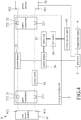
- FIG 4 is a block diagram illustrating an abnormality detecting system to be used for a solar power grid 9 according to one embodiment of the disclosure.
- the solar power grid 9 includes a solar power module 91, a power inverter 92 and an external power supply 93.
- the solar power module 91 and the power inverter 92 may be embodied using the corresponding components described in the embodiments of Figures 2 and 3 .
- the abnormality detecting system includes a circuit protecting unit 2, a processor 3 and a temperature sensor 4.
- the processor 3 and the temperature sensor 4 may be embodied using the corresponding components described in the embodiments of Figures 2 and 3 .
- the circuit protecting unit 2 includes an input component 21, an output component 22, a current detector 23, a power switch 24, a control module 26, a power unit 27 and a kill switch 28. It is noted that the power unit 27 is a transformer configured to receive power from the external power supply 93, and to supply electricity to the processor 26.
- the input component 21 may be embodied using one that is described in the embodiment of Figure 2 .
- the output component 22 includes a first output port 221 and a second output port 222.
- the current detector 23 is connected between the second port 212 of the input component 21 and the second output port 222 of the output component 22.
- the power switch 24 is connected between the first port 211 of the input component 21 and the first output port 221 of the output component 22.
- the first output port 221 is also connected to the first receiving node 921 of the power inverter 92
- the second output port 222 is also connected to the second receiving node 922 of the power inverter 92.
- the first and second ports 211, 212 of the input component 21 receive the solar power signal from the solar power module 91 together, and the first and second output ports 221, 222 of the output component 22 output the solar power signal to the power inverter 92 together.
- the operations of the current detector 23 and the power switch 24 may be similar to those described in the embodiment of Figure 2 , and details thereof are omitted herein for the sake of brevity.
- the control module 26 is connected to the current detector 23, the power switch 24, the power unit 27 and the processor 3.
- the power unit 27 is connected to the kill switch 28, which is connected to the external power supply 93. That is to say, the circuit protecting unit 2 in this embodiment is powered by the external power supply 93.
- the control module 26 controls the power switch 24 to switch to the closed circuit state
- the electrical connection between the first output port 221 and the first port 211 is established.
- the control module 26 controls the power switch 24 to switch to the open circuit state
- the electrical connection between the first output port 221 and the first port 211 becomes disconnected.
- the power switch 24 is in the closed circuit state, and the solar power signal travels from the solar power module 91 through the circuit protecting unit 2 to the power inverter 92.
- the amount of electrical current flowing through the current detector 23 and the amount of electrical current of the converted power signal outputted by the power inverter 92 are transmitted to the processor 3.
- the processor 3 may determine that the solar power module 91 is functional and the power inverter 92 is not functional. In this case, if the solar power signal is continuously transmitted to the non-functional power inverter 92, adverse effects such as short-circuiting, sparks or fire may occur. As such, the processor 3 may be programmed to control the control module 26 to control the power switch 24 to switch to the open circuit state. In the open circuit state, the solar power signal cannot go through the circuit protecting unit 2, and therefore cannot reach the non-functional power inverter 92, thereby preventing potential accidents.
- the kill switch 28 is normally in a conductive state, in which electrical current can flow from the external power supply 93 to the power unit 27 through the kill switch 28 (such that the control module 26 is powered by the external power supply 93).
- the kill switch 28 may include a manual interface that enables manual operation (e.g., a button, a lever, etc.) and/or a remote interface that enables remote operation (e.g., a wireless communication chip that can receive a wireless signal) to switch to a non-conductive state, in which electrical current cannot flow through the kill switch 28.
- the control module 26 of the circuit protecting unit 2 becomes unpowered, and therefore the solar power signal cannot go through the circuit protecting unit 2 since the power switch 24 would switch to a cutoff mode because of the lack of power.
- relevant personnel may operate the kill switch 28 to switch to the non-conductive state.
- FIG 5 is a block diagram illustrating an abnormality detecting system to be used for a solar power grid 9 according to one embodiment of the disclosure.
- the solar power grid 9 includes five solar power modules 91 and three power inverters 92.
- Each of the solar power modules 91 may be embodied using the one described in the embodiment of Figure 4 .
- each of the power inverters 92 may be connected to one or more solar power modules 91 to receive the solar power signal(s) therefrom.
- a top one of the power inverters 92 is connected to three solar power modules 91.
- the top one of the power inverters 92 may be equipped with three MPPT modules for configuring the power inverter 92 to maximize power extraction from the three connected solar power modules 91, respectively. It is noted that operations of the MPPT modules are readily known in the related art, and details thereof are omitted herein for the sake of brevity.
- the top one of the power inverters 92 may be configured to measure a number of parameters associated with each of the connected solar power modules 91 via the MPPT module corresponding to the solar power module 91. When it is determined that the input impedance seen from the power inverter 92 is lower than the predetermined impedance, the power inverter 92 is configured to proceed to generate the error signal.
- the solar power grid 9 includes an external power supply 93.
- the abnormality detecting system includes five circuit protecting units 2, a processor 3 and a temperature sensor 4. Each of these components in this embodiment may be embodied using a corresponding component described in the embodiment of Figure 4 , and some of the components of the circuit protecting units 2 are omitted in Figure 5 for the sake of simplicity.
- Each of the circuit protecting units 2 is disposed between a respective one of the solar power modules 91 and one of the power inverters 92, is powered by the external power supply 93 via the kill switch 28, and is connected to the processor 3.
- the top three circuit protecting units 2 are connected to the top one of the power inverters 92. It is noted that in other embodiments, other connection relations among the solar power modules 91, the circuit protecting units 2 and the power inverters 92 may be employed.
- a corresponding kill switch 28 may be operated to switch to the non-conductive state, as described in the embodiment of Figure 4 . As such, the solar power signal cannot go through the circuit protecting unit 2.
- the processor 3 may be also programmed to periodically (e.g., once a day) perform the reset operation on the abnormality detecting system.
- the processor 3 may be programmed to, at a certain time of each day, control the control modules 26 respectively of the circuit protecting units 2 to control the corresponding power switches 24 to switch to the open circuit state.
- the processor 3 may be programmed to control the control modules 26 of the circuit protecting units 2 to control the corresponding power switches 24 to switch to the closed circuit state, so as to therefore resume operation.
- the reset operation may be done sequentially with respect to the circuit protecting units 2. That is, the processor 3 may control the control modules 26 of the circuit protecting units 2 to control the corresponding power switches 24 to switch to the closed circuit state one by one.
- each of the power inverters 92 is configured to measure the DC voltage value of the solar power signal outputted by each solar power module 91 that is electrically connected thereto, and to measure the input impedance seen from the power inverter 92. Accordingly, for any one of the power inverters 92, when it is determined that an input impedance detected by the power inverter 92 is different from an associated normal value, the power inverter 92 proceeds to transmit the error signal to the processor 3 and then shuts down. In response to receipt of the error signal from the power inverter 92, the processor 3 is configured to operate in a troubleshooting mode.
- the processor 3 first controls the control module 26 of the circuit protecting unit 2 to switch the corresponding power switch 24 to the open circuit state. For example, in the embodiment of Figure 5 , when the error signal is received from the top one of the power inverters 92, the processor 3 controls the control modules 26 of the top three of the circuit protecting units 2 to switch the power switches 24 to the open circuit state.
- the processor 3 conducts a test procedure in which the processor 3 controls the control modules 26 of the circuit protecting units 2 that are connected to the power inverter 92, one by one, to switch the corresponding power switches 24 to the closed circuit state for a predetermined time period (e.g., one minute) before switching the corresponding power switch 24 back to the open circuit state.
- a predetermined time period e.g., one minute
- the processor 3 is configured to determine whether the error signal is still received from the top one of the power inverters 92, so as to determine which one (s) of the corresponding solar power modules 91 is non-functional.
- the processor 3 is configured to determine whether a component of the solar power grid 9 connected to the power switch 24 is functional based on whether an error signal is received from the one of the power inverters 92, and to generate a message that indicates the result of the determination and that can be used for further analysis .
- the processor 3 is further configured to control the control module 26 of each of the circuit protecting units 2 that is connected to the one of the power inverters 92 determined to be functional to switch the corresponding power switch 24 to the closed circuit state, thereby allowing relevant personnel to proceed to repair the part(s) of the solar power grid 9 that is determined to be non-functional.
- the embodiments of the disclosure provide an abnormality detecting system that can be installed in a front end of a solar power grid.
- the abnormality detecting system may be disposed between at least one solar power module and at least one power inverter.
- the abnormality detecting system when a part of the solar power module (e.g., one or more of the solar panels) or a part of the power inverter becomes non-functional, or when an adverse situation (e.g., a fire) has occurred, the abnormality detecting system may be controlled to or may automatically prevent the solar power signal from being transmitted to the power inverter, so as to prevent additional damages to the solar power grid.
- the abnormality detecting system may be controlled to perform the reset operation, and in the case an error signal is generated, perform the troubleshooting operation so as to determine which parts of the solar power grid needs repair.
- the abnormality detecting system includes a kill switch to enable relevant personnel to immediately un-power the circuit protecting unit in emergency situations.
Landscapes
- Engineering & Computer Science (AREA)
- Power Engineering (AREA)
- Artificial Intelligence (AREA)
- Evolutionary Computation (AREA)
- Photovoltaic Devices (AREA)
- Inverter Devices (AREA)
- Supply And Distribution Of Alternating Current (AREA)
- Emergency Protection Circuit Devices (AREA)
Applications Claiming Priority (2)
| Application Number | Priority Date | Filing Date | Title |
|---|---|---|---|
| TW109123086A TWI748552B (zh) | 2020-07-08 | 2020-07-08 | 太陽能直流饋線防災系統 |
| TW109140960A TWI737547B (zh) | 2020-11-23 | 2020-11-23 | 太陽能直流饋線防災系統 |
Publications (3)
| Publication Number | Publication Date |
|---|---|
| EP3937362A1 true EP3937362A1 (fr) | 2022-01-12 |
| EP3937362B1 EP3937362B1 (fr) | 2025-07-02 |
| EP3937362C0 EP3937362C0 (fr) | 2025-07-02 |
Family
ID=76765058
Family Applications (1)
| Application Number | Title | Priority Date | Filing Date |
|---|---|---|---|
| EP21183741.4A Active EP3937362B1 (fr) | 2020-07-08 | 2021-07-05 | Système de détection d'anomalie pour un réseau d'énergie solaire |
Country Status (7)
| Country | Link |
|---|---|
| US (1) | US12003095B2 (fr) |
| EP (1) | EP3937362B1 (fr) |
| JP (1) | JP7154644B2 (fr) |
| KR (1) | KR102608749B1 (fr) |
| CN (1) | CN113410825B (fr) |
| AU (1) | AU2021204712B2 (fr) |
| MY (1) | MY203713A (fr) |
Families Citing this family (4)
| Publication number | Priority date | Publication date | Assignee | Title |
|---|---|---|---|---|
| US20210351612A1 (en) * | 2020-05-11 | 2021-11-11 | Duke Energy Corporation | Solar inverter power output communications methods, and related computer program products |
| CN113131518B (zh) * | 2021-04-19 | 2022-05-24 | 阳光电源股份有限公司 | 一种mlpe光伏系统及其mlpe设备检测方法 |
| JP7849209B2 (ja) * | 2022-03-31 | 2026-04-21 | 本田技研工業株式会社 | 電力システム及び推定方法 |
| JP2023174193A (ja) * | 2022-05-27 | 2023-12-07 | Ntn株式会社 | 発電ユニット |
Citations (3)
| Publication number | Priority date | Publication date | Assignee | Title |
|---|---|---|---|---|
| US20020085397A1 (en) * | 2000-11-27 | 2002-07-04 | Masaki Suzui | Power converting apparatus, control method therefor, and power generation system |
| WO2004110659A2 (fr) * | 2003-06-09 | 2004-12-23 | Seahorse Power Company | Appareil de compactage solaire |
| CN106992540B (zh) * | 2017-04-20 | 2019-09-03 | 中南大学 | 一种无通信功率优化器的光伏系统及其开路故障诊断方法 |
Family Cites Families (18)
| Publication number | Priority date | Publication date | Assignee | Title |
|---|---|---|---|---|
| JP2943133B2 (ja) * | 1994-04-30 | 1999-08-30 | キヤノン株式会社 | 絶縁状態測定方法、絶縁状態判定装置及びそれを用いた分散型発電装置 |
| JPH09327179A (ja) | 1996-06-05 | 1997-12-16 | Mitsubishi Electric Corp | 交直変換器の異常検出装置および保護装置 |
| JP3731970B2 (ja) | 1997-03-28 | 2006-01-05 | 株式会社ダイヘン | 太陽光発電システム |
| US6593520B2 (en) * | 2000-02-29 | 2003-07-15 | Canon Kabushiki Kaisha | Solar power generation apparatus and control method therefor |
| JP2005168156A (ja) | 2003-12-02 | 2005-06-23 | Mitsubishi Heavy Ind Ltd | 地絡対策装置及び発電システム |
| US20110090607A1 (en) * | 2009-10-20 | 2011-04-21 | Luebke Charles J | String and system employing direct current electrical generating modules and a number of string protectors |
| US8659858B2 (en) * | 2010-08-24 | 2014-02-25 | Sanyo Electric Co., Ltd. | Ground-fault detecting device, current collecting box using the ground-fault detecting device, and photovoltaic power generating device using the current collecting box |
| DE102011008140A1 (de) * | 2010-08-31 | 2012-03-01 | Ellenberger & Poensgen Gmbh | Verfahren und Vorrichtung zum Schalten einer Gleichspannungsanlage |
| GB2498791A (en) * | 2012-01-30 | 2013-07-31 | Solaredge Technologies Ltd | Photovoltaic panel circuitry |
| DE102012218504A1 (de) * | 2012-10-11 | 2014-04-17 | Bender Gmbh & Co. Kg | Differenzstrom-Überwachungseinrichtung mit Lichtbogenerkennung |
| KR101430184B1 (ko) * | 2013-04-26 | 2014-08-13 | 주식회사 오키 | 비상절체회로 및 이를 이용한 전력변환장치 |
| CN103576089B (zh) * | 2013-08-07 | 2016-08-10 | 国家电网公司 | 一种基于串联动态电压恢复装置的高低电压穿越测试系统 |
| JP2016092881A (ja) | 2014-10-30 | 2016-05-23 | 有限会社バベッジ | ブレーカおよびブレーカ装置制御 |
| CN105846758A (zh) * | 2015-01-16 | 2016-08-10 | 台达电子工业股份有限公司 | 光伏发电系统及关断装置 |
| US11177663B2 (en) * | 2016-04-05 | 2021-11-16 | Solaredge Technologies Ltd. | Chain of power devices |
| WO2017214714A1 (fr) * | 2016-06-17 | 2017-12-21 | Celestica International Inc. | Système et procédé de commande d'un dispositif d'arrêt rapide de niveau de chaîne d'un réseau de panneaux solaires |
| EP3602711A1 (fr) | 2017-03-23 | 2020-02-05 | Imo Precision Controls Ltd | Dispositif de protection contre l'incendie pour modules photovoltaïques |
| KR102017551B1 (ko) | 2017-10-23 | 2019-09-03 | 원광전력주식회사 | 강화된 모니터링 기능을 갖는 태양광 발전 장치의 접속반 |
-
2021
- 2021-06-17 CN CN202110671333.7A patent/CN113410825B/zh active Active
- 2021-07-02 MY MYPI2021003790A patent/MY203713A/en unknown
- 2021-07-02 US US17/366,324 patent/US12003095B2/en active Active
- 2021-07-05 EP EP21183741.4A patent/EP3937362B1/fr active Active
- 2021-07-06 KR KR1020210088660A patent/KR102608749B1/ko active Active
- 2021-07-06 AU AU2021204712A patent/AU2021204712B2/en active Active
- 2021-07-07 JP JP2021112546A patent/JP7154644B2/ja active Active
Patent Citations (3)
| Publication number | Priority date | Publication date | Assignee | Title |
|---|---|---|---|---|
| US20020085397A1 (en) * | 2000-11-27 | 2002-07-04 | Masaki Suzui | Power converting apparatus, control method therefor, and power generation system |
| WO2004110659A2 (fr) * | 2003-06-09 | 2004-12-23 | Seahorse Power Company | Appareil de compactage solaire |
| CN106992540B (zh) * | 2017-04-20 | 2019-09-03 | 中南大学 | 一种无通信功率优化器的光伏系统及其开路故障诊断方法 |
Also Published As
| Publication number | Publication date |
|---|---|
| KR102608749B1 (ko) | 2023-12-01 |
| AU2021204712A1 (en) | 2022-01-27 |
| KR20220006475A (ko) | 2022-01-17 |
| EP3937362B1 (fr) | 2025-07-02 |
| AU2021204712B2 (en) | 2022-10-20 |
| US12003095B2 (en) | 2024-06-04 |
| CN113410825A (zh) | 2021-09-17 |
| CN113410825B (zh) | 2025-01-10 |
| JP2022016352A (ja) | 2022-01-21 |
| EP3937362C0 (fr) | 2025-07-02 |
| JP7154644B2 (ja) | 2022-10-18 |
| US20220014015A1 (en) | 2022-01-13 |
| MY203713A (en) | 2024-07-15 |
Similar Documents
| Publication | Publication Date | Title |
|---|---|---|
| EP3937362B1 (fr) | Système de détection d'anomalie pour un réseau d'énergie solaire | |
| KR100930132B1 (ko) | 모니터링 기능이 구비된 태양광 접속반 | |
| CN107037302B (zh) | 故障检测系统和电路 | |
| US5712572A (en) | Insulation state measurement method, insulation state judgement apparatus, and dispersion type power generating system using the same | |
| US9829529B2 (en) | Power supply apparatus | |
| US20150188487A1 (en) | Failure detection device, failure detection system, and failure detection method | |
| EP2975720B1 (fr) | Dispositif et procédé de détection d'isolation de modules photovoltaïques contre la masse et système de génération de puissance photovoltaïque raccordé au réseau | |
| CN112636694B (zh) | 一种光伏发电系统及方法 | |
| KR101761269B1 (ko) | 마이크로컨버터를 이용한 태양광 발전시스템 | |
| EP3074780B1 (fr) | Système d'alimentation électrique | |
| CN102474097A (zh) | 用于向电网供应来自多个光伏模块串列的电能的设备 | |
| EP2608341A1 (fr) | Dispositif de mise à la terre | |
| EP4047776A1 (fr) | Procédé et appareil de détection de défaut, et système de génération de puissance photovoltaïque connecté à un réseau | |
| CN105675966A (zh) | 一种基于差值计算方式的故障电弧检测方法及其保护装置 | |
| CN109997048B (zh) | 检测保护导体的阻抗的监测设备、方法和充电控制单元 | |
| KR101337927B1 (ko) | 전기안전보호기능 및 우회보정선로를 갖는 태양광발전 채널별 감시장치 | |
| KR20120086558A (ko) | 감시 및 중성선 대체기능이 구비된 태양광 발전시스템 | |
| EP4607211A1 (fr) | Convertisseur et son procédé de détection | |
| US20250125627A1 (en) | Energy management systems | |
| KR101646936B1 (ko) | 기능 확장형 태양광발전 채널별 감시장치를 구비하는 태양광 발전시스템 | |
| KR101030925B1 (ko) | 감시 및 중성선 대체기능이 구비된 태양광 발전시스템 | |
| KR101569199B1 (ko) | 임피던스 측정과 우회회로를 통한 화재방지형 태양광 발전 시스템. | |
| CN207612055U (zh) | 一种配网故障自动定位系统 | |
| JP2001298850A (ja) | 太陽光発電パネルの地絡検出装置 | |
| KR102670331B1 (ko) | Dc 개폐 기능을 가진 태양광 접속반 |
Legal Events
| Date | Code | Title | Description |
|---|---|---|---|
| PUAI | Public reference made under article 153(3) epc to a published international application that has entered the european phase |
Free format text: ORIGINAL CODE: 0009012 |
|
| STAA | Information on the status of an ep patent application or granted ep patent |
Free format text: STATUS: REQUEST FOR EXAMINATION WAS MADE |
|
| 17P | Request for examination filed |
Effective date: 20210705 |
|
| AK | Designated contracting states |
Kind code of ref document: A1 Designated state(s): AL AT BE BG CH CY CZ DE DK EE ES FI FR GB GR HR HU IE IS IT LI LT LU LV MC MK MT NL NO PL PT RO RS SE SI SK SM TR |
|
| B565 | Issuance of search results under rule 164(2) epc |
Effective date: 20211210 |
|
| STAA | Information on the status of an ep patent application or granted ep patent |
Free format text: STATUS: EXAMINATION IS IN PROGRESS |
|
| 17Q | First examination report despatched |
Effective date: 20240613 |
|
| GRAP | Despatch of communication of intention to grant a patent |
Free format text: ORIGINAL CODE: EPIDOSNIGR1 |
|
| STAA | Information on the status of an ep patent application or granted ep patent |
Free format text: STATUS: GRANT OF PATENT IS INTENDED |
|
| INTG | Intention to grant announced |
Effective date: 20250303 |
|
| RIN1 | Information on inventor provided before grant (corrected) |
Inventor name: HSU, CHUN-CHI |
|
| GRAS | Grant fee paid |
Free format text: ORIGINAL CODE: EPIDOSNIGR3 |
|
| GRAA | (expected) grant |
Free format text: ORIGINAL CODE: 0009210 |
|
| STAA | Information on the status of an ep patent application or granted ep patent |
Free format text: STATUS: THE PATENT HAS BEEN GRANTED |
|
| AK | Designated contracting states |
Kind code of ref document: B1 Designated state(s): AL AT BE BG CH CY CZ DE DK EE ES FI FR GB GR HR HU IE IS IT LI LT LU LV MC MK MT NL NO PL PT RO RS SE SI SK SM TR |
|
| REG | Reference to a national code |
Ref country code: GB Ref legal event code: FG4D |
|
| REG | Reference to a national code |
Ref country code: CH Ref legal event code: EP |
|
| REG | Reference to a national code |
Ref country code: DE Ref legal event code: R096 Ref document number: 602021033211 Country of ref document: DE |
|
| REG | Reference to a national code |
Ref country code: IE Ref legal event code: FG4D |
|
| U01 | Request for unitary effect filed |
Effective date: 20250721 |
|
| U07 | Unitary effect registered |
Designated state(s): AT BE BG DE DK EE FI FR IT LT LU LV MT NL PT RO SE SI Effective date: 20250728 |
|
| U20 | Renewal fee for the european patent with unitary effect paid |
Year of fee payment: 5 Effective date: 20250731 |
|
| PGFP | Annual fee paid to national office [announced via postgrant information from national office to epo] |
Ref country code: GB Payment date: 20250730 Year of fee payment: 5 |
|
| PG25 | Lapsed in a contracting state [announced via postgrant information from national office to epo] |
Ref country code: IS Free format text: LAPSE BECAUSE OF FAILURE TO SUBMIT A TRANSLATION OF THE DESCRIPTION OR TO PAY THE FEE WITHIN THE PRESCRIBED TIME-LIMIT Effective date: 20251102 |
|
| PG25 | Lapsed in a contracting state [announced via postgrant information from national office to epo] |
Ref country code: NO Free format text: LAPSE BECAUSE OF FAILURE TO SUBMIT A TRANSLATION OF THE DESCRIPTION OR TO PAY THE FEE WITHIN THE PRESCRIBED TIME-LIMIT Effective date: 20251002 |
|
| PG25 | Lapsed in a contracting state [announced via postgrant information from national office to epo] |
Ref country code: HR Free format text: LAPSE BECAUSE OF FAILURE TO SUBMIT A TRANSLATION OF THE DESCRIPTION OR TO PAY THE FEE WITHIN THE PRESCRIBED TIME-LIMIT Effective date: 20250702 |
|
| PG25 | Lapsed in a contracting state [announced via postgrant information from national office to epo] |
Ref country code: GR Free format text: LAPSE BECAUSE OF FAILURE TO SUBMIT A TRANSLATION OF THE DESCRIPTION OR TO PAY THE FEE WITHIN THE PRESCRIBED TIME-LIMIT Effective date: 20251003 |
|
| PG25 | Lapsed in a contracting state [announced via postgrant information from national office to epo] |
Ref country code: CZ Free format text: LAPSE BECAUSE OF FAILURE TO SUBMIT A TRANSLATION OF THE DESCRIPTION OR TO PAY THE FEE WITHIN THE PRESCRIBED TIME-LIMIT Effective date: 20250702 |
|
| PG25 | Lapsed in a contracting state [announced via postgrant information from national office to epo] |
Ref country code: PL Free format text: LAPSE BECAUSE OF FAILURE TO SUBMIT A TRANSLATION OF THE DESCRIPTION OR TO PAY THE FEE WITHIN THE PRESCRIBED TIME-LIMIT Effective date: 20250702 |
|
| PG25 | Lapsed in a contracting state [announced via postgrant information from national office to epo] |
Ref country code: RS Free format text: LAPSE BECAUSE OF FAILURE TO SUBMIT A TRANSLATION OF THE DESCRIPTION OR TO PAY THE FEE WITHIN THE PRESCRIBED TIME-LIMIT Effective date: 20251002 |
|
| PG25 | Lapsed in a contracting state [announced via postgrant information from national office to epo] |
Ref country code: ES Free format text: LAPSE BECAUSE OF FAILURE TO SUBMIT A TRANSLATION OF THE DESCRIPTION OR TO PAY THE FEE WITHIN THE PRESCRIBED TIME-LIMIT Effective date: 20250702 |
|
| REG | Reference to a national code |
Ref country code: CH Ref legal event code: H13 Free format text: ST27 STATUS EVENT CODE: U-0-0-H10-H13 (AS PROVIDED BY THE NATIONAL OFFICE) Effective date: 20260224 |
|
| PG25 | Lapsed in a contracting state [announced via postgrant information from national office to epo] |
Ref country code: SM Free format text: LAPSE BECAUSE OF FAILURE TO SUBMIT A TRANSLATION OF THE DESCRIPTION OR TO PAY THE FEE WITHIN THE PRESCRIBED TIME-LIMIT Effective date: 20250702 |
|
| PG25 | Lapsed in a contracting state [announced via postgrant information from national office to epo] |
Ref country code: CH Free format text: LAPSE BECAUSE OF NON-PAYMENT OF DUE FEES Effective date: 20250731 |
|
| PG25 | Lapsed in a contracting state [announced via postgrant information from national office to epo] |
Ref country code: SK Free format text: LAPSE BECAUSE OF FAILURE TO SUBMIT A TRANSLATION OF THE DESCRIPTION OR TO PAY THE FEE WITHIN THE PRESCRIBED TIME-LIMIT Effective date: 20250702 |
|
| PLBE | No opposition filed within time limit |
Free format text: ORIGINAL CODE: 0009261 |
|
| STAA | Information on the status of an ep patent application or granted ep patent |
Free format text: STATUS: NO OPPOSITION FILED WITHIN TIME LIMIT |