EP3938302B1 - Palier circulaire - Google Patents
Palier circulaire Download PDFInfo
- Publication number
- EP3938302B1 EP3938302B1 EP20708495.5A EP20708495A EP3938302B1 EP 3938302 B1 EP3938302 B1 EP 3938302B1 EP 20708495 A EP20708495 A EP 20708495A EP 3938302 B1 EP3938302 B1 EP 3938302B1
- Authority
- EP
- European Patent Office
- Prior art keywords
- conveying member
- circular store
- bulk material
- circular
- disposed
- Prior art date
- Legal status (The legal status is an assumption and is not a legal conclusion. Google has not performed a legal analysis and makes no representation as to the accuracy of the status listed.)
- Active
Links
Images


Classifications
-
- B—PERFORMING OPERATIONS; TRANSPORTING
- B65—CONVEYING; PACKING; STORING; HANDLING THIN OR FILAMENTARY MATERIAL
- B65G—TRANSPORT OR STORAGE DEVICES, e.g. CONVEYORS FOR LOADING OR TIPPING, SHOP CONVEYOR SYSTEMS OR PNEUMATIC TUBE CONVEYORS
- B65G65/00—Loading or unloading
- B65G65/30—Methods or devices for filling or emptying bunkers, hoppers, tanks, or like containers, of interest apart from their use in particular chemical or physical processes or their application in particular machines, e.g. not covered by a single other subclass
- B65G65/34—Emptying devices
- B65G65/36—Devices for emptying from the top
- B65G65/365—Devices for emptying from the top comprising a vertical passage located inside the container
-
- B—PERFORMING OPERATIONS; TRANSPORTING
- B65—CONVEYING; PACKING; STORING; HANDLING THIN OR FILAMENTARY MATERIAL
- B65G—TRANSPORT OR STORAGE DEVICES, e.g. CONVEYORS FOR LOADING OR TIPPING, SHOP CONVEYOR SYSTEMS OR PNEUMATIC TUBE CONVEYORS
- B65G65/00—Loading or unloading
- B65G65/02—Loading or unloading machines comprising essentially a conveyor for moving the loads associated with a device for picking-up the loads
- B65G65/06—Loading or unloading machines comprising essentially a conveyor for moving the loads associated with a device for picking-up the loads with endless scraping or elevating pick-up conveyors
-
- B—PERFORMING OPERATIONS; TRANSPORTING
- B65—CONVEYING; PACKING; STORING; HANDLING THIN OR FILAMENTARY MATERIAL
- B65G—TRANSPORT OR STORAGE DEVICES, e.g. CONVEYORS FOR LOADING OR TIPPING, SHOP CONVEYOR SYSTEMS OR PNEUMATIC TUBE CONVEYORS
- B65G65/00—Loading or unloading
- B65G65/30—Methods or devices for filling or emptying bunkers, hoppers, tanks, or like containers, of interest apart from their use in particular chemical or physical processes or their application in particular machines, e.g. not covered by a single other subclass
- B65G65/34—Emptying devices
- B65G65/36—Devices for emptying from the top
- B65G65/38—Mechanical devices
Definitions
- the invention relates to a circular storage facility for bulk goods for the simultaneous storage of different bulk goods.
- a round storage facility for bulk goods is known with a center column and a storage arm mounted horizontally pivotably on the center column and a bucket chain excavator that can be moved radially.
- the object of the invention is to provide a compact and long-term stable removal device for a circular storage facility with different bulk goods, which are separated from one another by partition walls, which can take up the bulk goods again without creating dead spaces.
- the circular storage facility for bulk goods has at least a first storage area for bulk goods and a second storage area for bulk goods.
- the first storage area and the second storage area are separated by at least one first partition.
- the circular bearing can have exactly two storage areas, the first storage area and the second storage area.
- the first storage area and the second storage area are separated from one another by a first partition on one side and by a second partition on the opposite side.
- the circular bearing preferably has three to ten bearing areas, which are each separated from one another by partition walls.
- the circular bearing particularly preferably has four to eight bearing areas which are each separated from one another by partition walls.
- the storage areas do not have to be of the same size, but can have different sizes. This is advantageous when different bulk materials are required in different quantities for the subsequent processes. Provision can be made for a storage area to remain permanently free of bulk material in order to enable permanent access.
- the circular bearing has at least one first removal device, the first removal device being arranged such that it can rotate about the central axis of the circular bearing.
- the central axis is arranged vertically.
- the central axis results from the perpendicular, which stands on the center of the circle enclosing the circular bearing.
- the first removal device has a first conveying element.
- the first removal device has a second axis, the second axis being arranged parallel and at a first axis distance from the central axis.
- the first extraction device has a first arm.
- the first arm is a structure that connects the central axis to the second axis.
- the first arm is rotatable about the central axis.
- the central axis and the second axis pass through the first arm.
- the first conveying element is connected to the first arm so that it can rotate about the second axis.
- the first conveying element Due to the rotatability of the first arm about the central axis and the first conveying element about the second axis, the first conveying element can be aligned parallel to the partition without dead space.
- the elements By connecting the elements to the axles, they can be sealed very well and reliably by radial seals and be protected with it. As a result, they do not have to be cleaned of dust and dirt during operation, as is the case with open rails.
- Examples of bulk goods that can be stored in a circular storage facility are limestone, sand, ore, gypsum, slag and clay, but also, for example, filter dust or ashes.
- the second axis passes through the outer end of the first arm, with the outer end of the first arm facing away from the central axis.
- the outer end is to mean that this axis does not have to be arranged at the outermost end, since then there can no longer be a supporting function. Therefore, the outer end is to be understood as the area that is removed from the outermost end by the width of the component.
- the first removal device has a first rotary drive, the first rotary drive being designed to rotate the first arm about the central axis.
- Rotary drives are robust, can be easily sealed with radial seals and are easy to control.
- the first removal device has a second rotary drive, the second rotary drive being designed to rotate the first conveying element about the second axis.
- Rotary drives are robust, can be easily sealed with radial seals and are easy to control.
- the first conveying element can be pivoted vertically.
- the vertical pivotability is preferably about a third axis.
- the vertical pivotability serves to adapt the first conveying element to the fill level of the bulk material.
- the layer thickness of the bulk material to be removed can be adjusted.
- the third axis is preferably arranged horizontally.
- the first conveying element is designed as a chain extension arm.
- a chain boom removes the bulk material, in which shovel-shaped or bucket-shaped devices are pulled over the bulk material and the bulk material is thus conveyed to the center of the circular storage facility.
- a chain extension arm thus preferably has a revolving transport unit on which the shovel-shaped or bucket-shaped devices are arranged.
- the transport unit can be in the form of a chain.
- the round bearing has a central chute, the central chute being arranged centrally around the central axis.
- the central chute transports the bulk material conveyed by the first conveying element downwards.
- the central chute is designed in particular in the form of a funnel.
- a removal belt is arranged below the circular storage facility and below the central chute, with the removal belt being designed for removing the bulk material.
- the removal belt extends beyond the circular storage facility in order to be able to transfer bulk material to other facilities.
- the circular bearing has at least three, preferably three to ten, particularly preferably four to eight bearing areas which are each separated from one another by partitions.
- the discharge point of the first conveying element is arranged above the central chute. On the one hand, this ensures that the bulk material is conveyed directly into the central chute by the first conveying element.
- the partition walls do not extend over the central chute, since a separating function is not required here. Thus, the first arm can rotate freely in the area above the central chute.
- the first conveying element has a first side area and a second side area, the first side area and the second side area being perpendicular along the longitudinal direction of the first conveyor element are arranged.
- a first cutting device is arranged on the first side area and a second cutting device is arranged on the second side area.
- the cutters can be used to scrape off material adhering to the partitions. This can prevent material accumulations, for example disk-like, from occurring, which could collapse and damage or overfill the first conveying element.
- the cutting devices are preferably arranged in the longitudinal direction of the first conveying element with the effective direction downwards.
- the cutting device is preferably arranged over the entire length of the first conveying element.
- a plurality of cutting devices can be arranged next to one another and/or offset in height from one another.
- the overall length of the first conveying element is greater than the axial distance of the central axis and the second axis from the first removal device. This enables a particularly economical embodiment.
- the round bearing has a first belt arm, the first belt arm being arranged such that it can rotate about the central axis.
- the first belt boom is designed for introducing bulk material into the first storage area and the second storage area.
- the round bearing preferably also has a first belt bridge, the first belt bridge being arranged above the first belt boom. The first belt bridge is designed to feed bulk material to the first belt boom.
- the first belt boom can be pivoted vertically. This allows the discharge height of the bulk material to be adjusted to the fill level, so that dust development is reduced.
- the first belt boom has a telescopic chute. This can affect the mechanical Tracking of the first belt boom on the different filling levels of the bulk material are dispensed with, only the length of the telescopic chute is adjusted according to the filling level, so that dust development is reduced.
- the circular storage facility has a transfer tower, with the transfer tower being arranged along the central axis.
- the first arm is part of the transfer tower.
- the first conveying element is arranged parallel to the first partition wall and at the end of step e) parallel to the second partition wall.
- the first conveying element can be moved in such a way that it can be arranged parallel to the respective partition wall.
- step f the method can be continued with step c) until the desired amount of bulk material has been removed from the first storage area.
- step c) the first conveying element is pivoted about the second axis in the direction of the first partition wall, the first arm being pivoted about the central axis counter to the pivoting direction of the first conveying element.
- This embodiment is preferred for storage areas with a small angle between the partitions.
- step c) in step c), the first conveying element is pivoted about the second axis in the direction of the first partition wall, with the first arm being pivoted about the central axis in the pivoting direction of the first conveying element, but with a smaller pivoting angle.
- This embodiment is preferred for storage areas with a large angle between the partition walls.
- Synchronous pivoting is particularly preferred, with the pivoting angles about the central axis and the second axis being dependent on the angle between the partition walls, the width of the partition walls and the width of the first conveying element.
- a synchronous pivoting can be achieved by different pivoting speeds. This enables continuous operation without loss of time for aligning the first conveying element parallel to the partition. In addition, this leads to a constant delivery volume during lateral pivoting. This is advantageous for the further process steps.
- pivoting about the central axis and about the second axis can be carried out alternately.
- the first conveyor element is raised in step c) at a first distance from the first partition and after that Reaching the first partition in step d) lowered into the end position.
- the first distance is less than the conveying width of the first conveying element. This makes it possible to scrape off material residues adhering to the first partition. This is preferred when cutting devices are attached to the side of the first conveying element.
- bulk material is stacked into the second storage area via the first belt boom. This can take place at the same time as the bulk material is removed from the first storage area.
- the circular storage facility has sensors for determining the fill level of the bulk material and for determining the position and position of the first conveying element. These sensors enable the bulk material discharge process to be automated.
- the round bearing preferably also has sensors for determining the position and position of the first belt boom or the dropping point. These sensors enable the bulk material loading process to be automated.
- Position means vertical tilting.
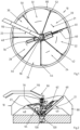
- Figure 1 show a circular bearing 10 from different perspectives.
- the exemplary circular bearing 10 has seven separate bearing areas 20, 22, 24, 26, 28, 30, 32 on.
- the storage areas 20, 22, 24, 26, 28, 30, 32 are separated by seven partitions 40, 42, 44, 46, 48, 50, 52.
- the round store 10 is arranged in a building 80 .
- the building 80 protects the bulk materials 21, 23 from environmental influences and reduces emissions, in particular noise and dust, to the environment.
- a transfer tower is arranged in the center of the round bearing 10 on the central axis 90 . Part of the transfer tower is a first removal device, which is formed from a first arm 140 and a first conveying element 60 .
- the first conveying element 60 can be pivoted vertically about the third axis via a lifting device 62 in order to be able to adapt to the fill level of the bulk material 21, 23.
- the first removal device has a counterweight 64 to balance the forces.
- the first conveying element 60 conveys bulk material into the central chute 120, from where the bulk material can be removed from the circular storage facility 10 via a discharge belt 130 .
- the circular storage facility 10 has a first belt bridge 110 at the upper end of the transfer tower, via which bulk material can be fed. From here, the bulk material falls onto the first belt arm 70, which is rotatably mounted about the central axis 90. In this way, bulk material can be introduced into each storage area 20, 22, 24, 26, 28, 30, 32.
- the first belt boom 70 in the example shown can be pivoted vertically.
- the first conveying element 60 is located between the first partition wall 40 and the second partition wall 42.
- the opening angle of the first storage area 20 between the first partition wall 40 and the second partition wall 42 is 35°. It can be seen that the width of the first conveying element 60 but also the widths of the first partition wall 40 and the second partition wall 42 would mean that without mobility about the second axis 100 bulk material could not be transported away completely from the first storage area 20 and without the formation of dead space it is possible.
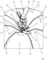
- the first conveying element 60 is arranged parallel and immediately adjacent to the second partition wall 42 .
- the first arm 140 is pivoted by 6° with respect to the first partition wall 40 and the first conveyor element 60 by a further 29° with respect to the first arm 140.
- the first arm 140 is pivoted by 29° in relation to the first partition wall 40 and the first conveying member 60 is pivoted by 29° in relation to the first arm 140 in the opposite direction.
- the first conveying element 60 is thus arranged parallel to the first partition wall 40 .
- the first arm 140 from the in 4 The position shown is pivoted clockwise by 23°, while at the same time the first conveying element 60 is pivoted counterclockwise by 58°. This is how the in figure 5 position shown.
- the movement is then reversed, the first arm 140 is pivoted counterclockwise by 23°, while the first conveying element 60 is pivoted clockwise by 58°.
- the first conveying element 60 is lowered by the height of the layer thickness of the bulk material to be removed.
- FIG. 6 shows how material adhering to the first partition wall 40 can be removed with a cutting device 66 which is arranged on the first conveying element.
- the first conveying element 60 is moved in the direction of the first partition wall 40 .
- the first conveying element 60 is raised.
- the conveying element 60 is lowered by the amount by which the first conveying element 60 was previously raised, plus the height of the layer thickness of the bulk material to be removed, which results from the desired conveying volume.
- the first cutting device 66 is guided very close to the first partition wall 40 in a material-free area. Adhering material is removed from the first partition wall 40 by the downward movement of the cutting device 66 .
Landscapes
- Engineering & Computer Science (AREA)
- Mechanical Engineering (AREA)
- Filling Or Emptying Of Bunkers, Hoppers, And Tanks (AREA)
Claims (19)
- Entrepôt circulaire (10) pour produits en vrac (21, 23), dans lequel l'entrepôt circulaire (10) présente au moins une première zone de stockage (20) pour des produits en vrac (21, 23) et une deuxième zone de stockage (22) pour des produits en vrac (21, 23), la première zone de stockage (20) et la deuxième zone de stockage (22) étant séparées par au moins une première cloison (40), dans lequel l'entrepôt circulaire (10) présente au moins un premier dispositif de prélèvement, le premier dispositif de prélèvement étant disposé en rotation autour de l'axe central (90) de l'entrepôt circulaire (10), dans lequel l'axe central (90) est disposé verticalement, dans lequel le premier dispositif de prélèvement présente un premier organe de transport (60),
caractérisé en ce que le premier dispositif de prélèvement présente un deuxième axe (100), le deuxième axe (100) étant disposé en parallèle et à une première distance d'axe en axe par rapport à l'axe central (90), dans lequel le premier dispositif de prélèvement présente un premier bras (140), le premier bras (140) pouvant tourner autour de l'axe central (90), l'axe central (90) et le deuxième axe (100) s'étendant à travers le premier bras (140), dans lequel le premier organe de transport (60) est relié au premier bras (140) en rotation autour du deuxième axe (100). - Entrepôt circulaire (10) selon la revendication 1, caractérisé en ce que le premier dispositif de prélèvement présente un premier dispositif d'entraînement en rotation, dans lequel le premier dispositif d'entraînement en rotation est réalisé pour une rotation du premier bras (140) autour de l'axe central (90).
- Entrepôt circulaire (10) selon l'une quelconque des revendications précédentes, caractérisé en ce que le premier dispositif de prélèvement présente un deuxième dispositif d'entraînement en rotation, le deuxième dispositif d'entraînement en rotation étant réalisé pour une rotation du premier organe de transport (60) autour du deuxième axe (100).
- Entrepôt circulaire (10) selon l'une quelconque des revendications précédentes, caractérisé en ce que le premier organe de transport (60) est pivotant verticalement.
- Entrepôt circulaire (10) selon l'une quelconque des revendications précédentes, caractérisé en ce que la longueur totale du premier organe de transport (60) est supérieure à la distance d'axe en axe de l'axe central (90) et du deuxième axe (100) par rapport au premier dispositif de prélèvement.
- Entrepôt circulaire (10) selon l'une quelconque des revendications précédentes, caractérisé en ce que le premier organe de transport (60) est réalisé sous forme de poutre à chaîne en porte-à-faux.
- Entrepôt circulaire (10) selon l'une quelconque des revendications précédentes, caractérisé en ce que l'entrepôt circulaire (10) présente une goulotte centrale (120), la goulotte centrale (120) étant disposée de manière centrée autour de l'axe central (90), dans lequel la goulotte centrale (120) évacue par le bas les produits en vrac (21, 23) transportés par le premier organe de transport (60).
- Entrepôt circulaire (10) selon la revendication 7, caractérisé en ce qu'une bande d'évacuation (130) est disposée au-dessous de l'entrepôt circulaire (10) et au-dessous de la goulotte centrale (120), la bande d'évacuation (130) étant réalisée pour évacuer les produits en vrac (21, 23).
- Entrepôt circulaire (10) selon l'une quelconque des revendications précédentes, caractérisé en ce que l'entrepôt circulaire présente au moins trois, de préférence de trois à dix, de manière particulièrement préférée de quatre à huit zones de stockage qui sont respectivement séparées les unes des autres par des cloisons.
- Entrepôt circulaire (10) selon l'une quelconque des revendications 7 à 9, caractérisé en ce que le point de déversement est disposé au-dessus de la goulotte centrale (120).
- Entrepôt circulaire (10) selon l'une quelconque des revendications précédentes, caractérisé en ce que le premier organe de transport (60) présente une première zone latérale et une deuxième zone latérale, dans lequel la première zone latérale et la deuxième zone latérale sont disposées verticalement le long de la direction longitudinale du premier organe de transport (60), dans lequel un premier dispositif de coupe (66) est disposé au niveau de la première zone latérale, dans lequel un deuxième dispositif de coupe (66) est disposé au niveau de la deuxième zone latérale.
- Entrepôt circulaire (10) selon l'une quelconque des revendications précédentes, caractérisé en ce que l'entrepôt circulaire (10) présente une première poutre à bande en porte-à-faux (70), la première poutre à bande en porte-à-faux (70) étant disposée en rotation autour de l'axe central (90), dans lequel la première poutre à bande en porte-à-faux (70) est réalisée pour charger des produits en vrac (21, 23) dans la première zone de stockage (20) et dans la deuxième zone de stockage (22).
- Entrepôt circulaire (10) selon la revendication 12, caractérisé en ce que l'entrepôt circulaire (10) présente un premier portique à bande (110), le premier portique à bande (110) étant disposé au-dessus de la première poutre à bande en porte-à-faux (70), dans lequel le premier portique à bande (110) est réalisé pour amener des produits en vrac (21, 23) à la première poutre à bande en porte-à-faux (70).
- Entrepôt circulaire (10) selon l'une quelconque des revendications 12 à 13, caractérisé en ce que la première poutre à bande en porte-à-faux (70) peut pivoter verticalement.
- Entrepôt circulaire (10) selon l'une quelconque des revendications 12 à 13, caractérisé en ce que la première poutre à bande en porte-à-faux (70) présente une goulotte télescopique.
- Entrepôt circulaire (10) selon l'une quelconque des revendications précédentes, caractérisé en ce que l'entrepôt circulaire (10) présente une tour de transfert, la tour de transfert étant disposée le long de l'axe central (90).
- Procédé permettant de décharger des produits en vrac (21, 23) à partir d'un entrepôt circulaire (10) selon l'une quelconque des revendications précédentes en combinaison avec la revendication 4, dans lequel la première zone de stockage (20) présente d'un côté une première cloison (40) et du côté opposé une deuxième cloison (42), le procédé présentant les étapes suivantes consistant à :a) disposer un premier organe de transport (60) du premier dispositif de prélèvement au-dessus de la première zone de stockage (20),b) abaisser le premier organe de transport (60) jusqu'à ce que le premier organe de transport (60) entre en contact avec les produits en vrac (21, 23) qui sont disposés dans la première zone de stockage (20),c) faire pivoter latéralement le premier organe de transport (60) en direction de la première cloison (40),d) abaisser le premier organe de transport (60) de la hauteur de l'épaisseur de couche à enlever des produits en vrac (21, 23),e) faire pivoter latéralement le premier organe de transport (60) de la première cloison (40) vers la deuxième cloison (42),f) abaisser le premier organe de transport (60) de la hauteur de l'épaisseur de couche à enlever des produits en vrac (21, 23),dans lequel, à la fin de l'étape c), le premier organe de transport (60) est disposé en parallèle à la première cloison (40), dans lequel, à la fin de l'étape e), le premier organe de transport (60) est disposé en parallèle à la deuxième cloison (42).
- Procédé selon la revendication 17, caractérisé en ce qu'à l'étape c), le premier organe de transport (60) est soulevé à une première distance par rapport à la première cloison (40), et après avoir atteint la première cloison (40) à l'étape d), est abaissé dans la position d'extrémité, la première distance étant inférieure à la largeur de transport du premier organe de transport (60).
- Procédé selon l'une quelconque des revendications 17 à 18, caractérisé en ce que les produits en vrac (21, 23) sont empilés dans une deuxième zone de stockage (22) par l'intermédiaire de la première poutre à bande en porte-à-faux (70).
Applications Claiming Priority (3)
| Application Number | Priority Date | Filing Date | Title |
|---|---|---|---|
| BE20195158A BE1027118B1 (de) | 2019-03-13 | 2019-03-13 | Rundlager |
| DE102019203416.0A DE102019203416A1 (de) | 2019-03-13 | 2019-03-13 | Rundlager |
| PCT/EP2020/055773 WO2020182590A1 (fr) | 2019-03-13 | 2020-03-05 | Palier circulaire |
Publications (3)
| Publication Number | Publication Date |
|---|---|
| EP3938302A1 EP3938302A1 (fr) | 2022-01-19 |
| EP3938302C0 EP3938302C0 (fr) | 2023-06-07 |
| EP3938302B1 true EP3938302B1 (fr) | 2023-06-07 |
Family
ID=69740370
Family Applications (1)
| Application Number | Title | Priority Date | Filing Date |
|---|---|---|---|
| EP20708495.5A Active EP3938302B1 (fr) | 2019-03-13 | 2020-03-05 | Palier circulaire |
Country Status (2)
| Country | Link |
|---|---|
| EP (1) | EP3938302B1 (fr) |
| WO (1) | WO2020182590A1 (fr) |
Family Cites Families (6)
| Publication number | Priority date | Publication date | Assignee | Title |
|---|---|---|---|---|
| FR2338206A1 (fr) | 1976-01-13 | 1977-08-12 | Interpar | Installation pour le stockage et la manutention de produits granules ou pulverulents |
| DE3121518C2 (de) | 1981-05-29 | 1987-04-02 | Fertigbau Schätz GmbH & Co KG, 8399 Rotthalmünster | Rundlager für Schüttgut |
| DE3136316C2 (de) | 1981-09-12 | 1986-02-27 | PHB Weserhütte AG, 5000 Köln | Entladevorrichtung, insbesondere zur Aufnahme von Schüttgut aus Waggons od. dgl. |
| DE3524200A1 (de) | 1985-07-05 | 1987-01-15 | Rieter Werke Haendle | Rundlager |
| FR2587010B1 (fr) | 1985-09-06 | 1987-10-30 | Fives Cail Babcock | Gratteur de reprise pour aire de stockage circulaire |
| CN206013914U (zh) | 2016-08-31 | 2017-03-15 | 中冶赛迪工程技术股份有限公司 | 一种圆形储料场 |
-
2020
- 2020-03-05 WO PCT/EP2020/055773 patent/WO2020182590A1/fr not_active Ceased
- 2020-03-05 EP EP20708495.5A patent/EP3938302B1/fr active Active
Also Published As
| Publication number | Publication date |
|---|---|
| EP3938302C0 (fr) | 2023-06-07 |
| WO2020182590A1 (fr) | 2020-09-17 |
| EP3938302A1 (fr) | 2022-01-19 |
Similar Documents
| Publication | Publication Date | Title |
|---|---|---|
| DE69201627T2 (de) | Einrichtung zum Fördern und volumetrischen Dosieren von Schüttgut. | |
| DE2532788C3 (de) | Silo für Gras, Heu, gehackten Mais und ähnliches Gut | |
| DE2331798C3 (de) | Anlage zum Homogenisieren von Schüttgut | |
| DE2813056A1 (de) | Trennvorrichtung zum wiedergewinnen der zuschlagstoffe aus nicht-abgebundenem beton | |
| DE3390175C2 (fr) | ||
| EP3938302B1 (fr) | Palier circulaire | |
| DE8704843U1 (de) | Einrichtung zum Umsetzen von Müll auf einem Kompostierfeld | |
| BE1027118B1 (de) | Rundlager | |
| CH658233A5 (de) | Zwischenspeicher zum aufnehmen einzelner kleinteile und be- oder/und entladestation fuer einen solchen zwischenspeicher. | |
| DE102019203416A1 (de) | Rundlager | |
| EP0841137A2 (fr) | Installation et procédé pour la fabrication de matériaux à mélanger, en particulier pour mortier sec | |
| DE3626003A1 (de) | Silo fuer schuettgut | |
| DE2808234C2 (de) | Einrichtung zum Zuführen von Material und Füllen senkrecht angeordneter Förderschnecken | |
| CH642327A5 (de) | Anlage fuer die behandlung von in warenkoerben befindlichen waren in behandlungsbaedern. | |
| DE4114903A1 (de) | Vorrichtung zum abraeumen einer schuettguthalde | |
| DE2324883C2 (de) | Rundsilo zum Speichern von leicht rieselfähigem Schüttgut | |
| DE3524778C1 (de) | Vorrichtung zum Aufnehmen und Abfoerdern von in Haufwerken gelagerten Feldfruechten | |
| DE3121518A1 (de) | Rundlager fuer schuettgut | |
| DE3329879C2 (de) | Rundsilo | |
| DE3404934A1 (de) | Rundsilo | |
| EP3908544B1 (fr) | Système de déblaiement d'un lit mixte et procédé pour faire fonctionner un système de déblaiement | |
| DE2837881A1 (de) | Vorrichtung zum auflesen von losen produkten | |
| DE1432040C3 (de) | Verfahren und Anlage zum kontinuierlichen Homogenisieren von körnigem Schüttgut großer Mengen | |
| EP0111328A1 (fr) | Dispositif de transport à bande pour matériaux en vrac | |
| DE2541583B2 (de) | Vorrichtung zum einebnen und ausraeumen von schuettgut in bzw. aus gutbehandlungsraeumen, insbesondere fuer maelzereien |
Legal Events
| Date | Code | Title | Description |
|---|---|---|---|
| STAA | Information on the status of an ep patent application or granted ep patent |
Free format text: STATUS: UNKNOWN |
|
| STAA | Information on the status of an ep patent application or granted ep patent |
Free format text: STATUS: THE INTERNATIONAL PUBLICATION HAS BEEN MADE |
|
| PUAI | Public reference made under article 153(3) epc to a published international application that has entered the european phase |
Free format text: ORIGINAL CODE: 0009012 |
|
| STAA | Information on the status of an ep patent application or granted ep patent |
Free format text: STATUS: REQUEST FOR EXAMINATION WAS MADE |
|
| 17P | Request for examination filed |
Effective date: 20211013 |
|
| AK | Designated contracting states |
Kind code of ref document: A1 Designated state(s): AL AT BE BG CH CY CZ DE DK EE ES FI FR GB GR HR HU IE IS IT LI LT LU LV MC MK MT NL NO PL PT RO RS SE SI SK SM TR |
|
| DAV | Request for validation of the european patent (deleted) | ||
| DAX | Request for extension of the european patent (deleted) | ||
| RAP3 | Party data changed (applicant data changed or rights of an application transferred) |
Owner name: THYSSENKRUPP AG Owner name: THYSSENKRUPP INDUSTRIAL SOLUTIONS AG |
|
| GRAP | Despatch of communication of intention to grant a patent |
Free format text: ORIGINAL CODE: EPIDOSNIGR1 |
|
| STAA | Information on the status of an ep patent application or granted ep patent |
Free format text: STATUS: GRANT OF PATENT IS INTENDED |
|
| INTG | Intention to grant announced |
Effective date: 20221206 |
|
| GRAS | Grant fee paid |
Free format text: ORIGINAL CODE: EPIDOSNIGR3 |
|
| GRAA | (expected) grant |
Free format text: ORIGINAL CODE: 0009210 |
|
| STAA | Information on the status of an ep patent application or granted ep patent |
Free format text: STATUS: THE PATENT HAS BEEN GRANTED |
|
| AK | Designated contracting states |
Kind code of ref document: B1 Designated state(s): AL AT BE BG CH CY CZ DE DK EE ES FI FR GB GR HR HU IE IS IT LI LT LU LV MC MK MT NL NO PL PT RO RS SE SI SK SM TR |
|
| REG | Reference to a national code |
Ref country code: GB Ref legal event code: FG4D Free format text: NOT ENGLISH |
|
| REG | Reference to a national code |
Ref country code: CH Ref legal event code: EP Ref country code: AT Ref legal event code: REF Ref document number: 1574469 Country of ref document: AT Kind code of ref document: T Effective date: 20230615 |
|
| REG | Reference to a national code |
Ref country code: DE Ref legal event code: R096 Ref document number: 502020003642 Country of ref document: DE |
|
| U01 | Request for unitary effect filed |
Effective date: 20230705 |
|
| U07 | Unitary effect registered |
Designated state(s): AT BE BG DE DK EE FI FR IT LT LU LV MT NL PT SE SI Effective date: 20230717 |
|
| REG | Reference to a national code |
Ref country code: LT Ref legal event code: MG9D |
|
| PG25 | Lapsed in a contracting state [announced via postgrant information from national office to epo] |
Ref country code: NO Free format text: LAPSE BECAUSE OF FAILURE TO SUBMIT A TRANSLATION OF THE DESCRIPTION OR TO PAY THE FEE WITHIN THE PRESCRIBED TIME-LIMIT Effective date: 20230907 Ref country code: ES Free format text: LAPSE BECAUSE OF FAILURE TO SUBMIT A TRANSLATION OF THE DESCRIPTION OR TO PAY THE FEE WITHIN THE PRESCRIBED TIME-LIMIT Effective date: 20230607 |
|
| PG25 | Lapsed in a contracting state [announced via postgrant information from national office to epo] |
Ref country code: RS Free format text: LAPSE BECAUSE OF FAILURE TO SUBMIT A TRANSLATION OF THE DESCRIPTION OR TO PAY THE FEE WITHIN THE PRESCRIBED TIME-LIMIT Effective date: 20230607 Ref country code: HR Free format text: LAPSE BECAUSE OF FAILURE TO SUBMIT A TRANSLATION OF THE DESCRIPTION OR TO PAY THE FEE WITHIN THE PRESCRIBED TIME-LIMIT Effective date: 20230607 Ref country code: GR Free format text: LAPSE BECAUSE OF FAILURE TO SUBMIT A TRANSLATION OF THE DESCRIPTION OR TO PAY THE FEE WITHIN THE PRESCRIBED TIME-LIMIT Effective date: 20230908 |
|
| PG25 | Lapsed in a contracting state [announced via postgrant information from national office to epo] |
Ref country code: SK Free format text: LAPSE BECAUSE OF FAILURE TO SUBMIT A TRANSLATION OF THE DESCRIPTION OR TO PAY THE FEE WITHIN THE PRESCRIBED TIME-LIMIT Effective date: 20230607 |
|
| PG25 | Lapsed in a contracting state [announced via postgrant information from national office to epo] |
Ref country code: IS Free format text: LAPSE BECAUSE OF FAILURE TO SUBMIT A TRANSLATION OF THE DESCRIPTION OR TO PAY THE FEE WITHIN THE PRESCRIBED TIME-LIMIT Effective date: 20231007 |
|
| PG25 | Lapsed in a contracting state [announced via postgrant information from national office to epo] |
Ref country code: SM Free format text: LAPSE BECAUSE OF FAILURE TO SUBMIT A TRANSLATION OF THE DESCRIPTION OR TO PAY THE FEE WITHIN THE PRESCRIBED TIME-LIMIT Effective date: 20230607 Ref country code: SK Free format text: LAPSE BECAUSE OF FAILURE TO SUBMIT A TRANSLATION OF THE DESCRIPTION OR TO PAY THE FEE WITHIN THE PRESCRIBED TIME-LIMIT Effective date: 20230607 Ref country code: RO Free format text: LAPSE BECAUSE OF FAILURE TO SUBMIT A TRANSLATION OF THE DESCRIPTION OR TO PAY THE FEE WITHIN THE PRESCRIBED TIME-LIMIT Effective date: 20230607 Ref country code: IS Free format text: LAPSE BECAUSE OF FAILURE TO SUBMIT A TRANSLATION OF THE DESCRIPTION OR TO PAY THE FEE WITHIN THE PRESCRIBED TIME-LIMIT Effective date: 20231007 Ref country code: CZ Free format text: LAPSE BECAUSE OF FAILURE TO SUBMIT A TRANSLATION OF THE DESCRIPTION OR TO PAY THE FEE WITHIN THE PRESCRIBED TIME-LIMIT Effective date: 20230607 |
|
| PG25 | Lapsed in a contracting state [announced via postgrant information from national office to epo] |
Ref country code: PL Free format text: LAPSE BECAUSE OF FAILURE TO SUBMIT A TRANSLATION OF THE DESCRIPTION OR TO PAY THE FEE WITHIN THE PRESCRIBED TIME-LIMIT Effective date: 20230607 |
|
| REG | Reference to a national code |
Ref country code: DE Ref legal event code: R097 Ref document number: 502020003642 Country of ref document: DE |
|
| PLBE | No opposition filed within time limit |
Free format text: ORIGINAL CODE: 0009261 |
|
| STAA | Information on the status of an ep patent application or granted ep patent |
Free format text: STATUS: NO OPPOSITION FILED WITHIN TIME LIMIT |
|
| U20 | Renewal fee for the european patent with unitary effect paid |
Year of fee payment: 5 Effective date: 20240325 |
|
| 26N | No opposition filed |
Effective date: 20240308 |
|
| U1K | Transfer of rights of the unitary patent after the registration of the unitary effect |
Owner name: THYSSENKRUPP AG; DE Owner name: THYSSENKRUPP POLYSIUS GMBH; DE |
|
| REG | Reference to a national code |
Ref country code: CH Ref legal event code: PL |
|
| PG25 | Lapsed in a contracting state [announced via postgrant information from national office to epo] |
Ref country code: MC Free format text: LAPSE BECAUSE OF FAILURE TO SUBMIT A TRANSLATION OF THE DESCRIPTION OR TO PAY THE FEE WITHIN THE PRESCRIBED TIME-LIMIT Effective date: 20230607 |
|
| GBPC | Gb: european patent ceased through non-payment of renewal fee |
Effective date: 20240305 |
|
| PG25 | Lapsed in a contracting state [announced via postgrant information from national office to epo] |
Ref country code: MC Free format text: LAPSE BECAUSE OF FAILURE TO SUBMIT A TRANSLATION OF THE DESCRIPTION OR TO PAY THE FEE WITHIN THE PRESCRIBED TIME-LIMIT Effective date: 20230607 |
|
| PG25 | Lapsed in a contracting state [announced via postgrant information from national office to epo] |
Ref country code: GB Free format text: LAPSE BECAUSE OF NON-PAYMENT OF DUE FEES Effective date: 20240305 |
|
| PG25 | Lapsed in a contracting state [announced via postgrant information from national office to epo] |
Ref country code: IE Free format text: LAPSE BECAUSE OF NON-PAYMENT OF DUE FEES Effective date: 20240305 |
|
| PG25 | Lapsed in a contracting state [announced via postgrant information from national office to epo] |
Ref country code: IE Free format text: LAPSE BECAUSE OF NON-PAYMENT OF DUE FEES Effective date: 20240305 Ref country code: GB Free format text: LAPSE BECAUSE OF NON-PAYMENT OF DUE FEES Effective date: 20240305 Ref country code: CH Free format text: LAPSE BECAUSE OF NON-PAYMENT OF DUE FEES Effective date: 20240331 |
|
| U20 | Renewal fee for the european patent with unitary effect paid |
Year of fee payment: 6 Effective date: 20250325 |
|
| PG25 | Lapsed in a contracting state [announced via postgrant information from national office to epo] |
Ref country code: CY Free format text: LAPSE BECAUSE OF FAILURE TO SUBMIT A TRANSLATION OF THE DESCRIPTION OR TO PAY THE FEE WITHIN THE PRESCRIBED TIME-LIMIT; INVALID AB INITIO Effective date: 20200305 |
|
| PG25 | Lapsed in a contracting state [announced via postgrant information from national office to epo] |
Ref country code: HU Free format text: LAPSE BECAUSE OF FAILURE TO SUBMIT A TRANSLATION OF THE DESCRIPTION OR TO PAY THE FEE WITHIN THE PRESCRIBED TIME-LIMIT; INVALID AB INITIO Effective date: 20200305 |
|
| PG25 | Lapsed in a contracting state [announced via postgrant information from national office to epo] |
Ref country code: TR Free format text: LAPSE BECAUSE OF FAILURE TO SUBMIT A TRANSLATION OF THE DESCRIPTION OR TO PAY THE FEE WITHIN THE PRESCRIBED TIME-LIMIT Effective date: 20230607 |
|
| U20 | Renewal fee for the european patent with unitary effect paid |
Year of fee payment: 7 Effective date: 20260326 |