EP3938577B1 - Système de chemin de fer à tube à vide - Google Patents
Système de chemin de fer à tube à vide Download PDFInfo
- Publication number
- EP3938577B1 EP3938577B1 EP20712885.1A EP20712885A EP3938577B1 EP 3938577 B1 EP3938577 B1 EP 3938577B1 EP 20712885 A EP20712885 A EP 20712885A EP 3938577 B1 EP3938577 B1 EP 3938577B1
- Authority
- EP
- European Patent Office
- Prior art keywords
- vacuum tube
- support plates
- tube
- railway system
- sections
- Prior art date
- Legal status (The legal status is an assumption and is not a legal conclusion. Google has not performed a legal analysis and makes no representation as to the accuracy of the status listed.)
- Active
Links
Images



Classifications
-
- E—FIXED CONSTRUCTIONS
- E01—CONSTRUCTION OF ROADS, RAILWAYS, OR BRIDGES
- E01B—PERMANENT WAY; PERMANENT-WAY TOOLS; MACHINES FOR MAKING RAILWAYS OF ALL KINDS
- E01B25/00—Tracks for special kinds of railways
- E01B25/30—Tracks for magnetic suspension or levitation vehicles
-
- B—PERFORMING OPERATIONS; TRANSPORTING
- B61—RAILWAYS
- B61B—RAILWAY SYSTEMS; EQUIPMENT THEREFOR NOT OTHERWISE PROVIDED FOR
- B61B13/00—Other railway systems
- B61B13/08—Sliding or levitation systems
-
- B—PERFORMING OPERATIONS; TRANSPORTING
- B61—RAILWAYS
- B61B—RAILWAY SYSTEMS; EQUIPMENT THEREFOR NOT OTHERWISE PROVIDED FOR
- B61B13/00—Other railway systems
- B61B13/10—Tunnel systems
-
- E—FIXED CONSTRUCTIONS
- E01—CONSTRUCTION OF ROADS, RAILWAYS, OR BRIDGES
- E01B—PERMANENT WAY; PERMANENT-WAY TOOLS; MACHINES FOR MAKING RAILWAYS OF ALL KINDS
- E01B1/00—Ballastway; Other means for supporting the sleepers or the track; Drainage of the ballastway
- E01B1/001—Track with ballast
-
- E—FIXED CONSTRUCTIONS
- E01—CONSTRUCTION OF ROADS, RAILWAYS, OR BRIDGES
- E01B—PERMANENT WAY; PERMANENT-WAY TOOLS; MACHINES FOR MAKING RAILWAYS OF ALL KINDS
- E01B2/00—General structure of permanent way
- E01B2/003—Arrangement of tracks on bridges or in tunnels
-
- E—FIXED CONSTRUCTIONS
- E04—BUILDING
- E04B—GENERAL BUILDING CONSTRUCTIONS; WALLS, e.g. PARTITIONS; ROOFS; FLOORS; CEILINGS; INSULATION OR OTHER PROTECTION OF BUILDINGS
- E04B1/00—Constructions in general; Structures which are not restricted either to walls, e.g. partitions, or floors or ceilings or roofs
- E04B1/32—Arched structures; Vaulted structures; Folded structures
- E04B1/3205—Structures with a longitudinal horizontal axis, e.g. cylindrical or prismatic structures
-
- E—FIXED CONSTRUCTIONS
- E01—CONSTRUCTION OF ROADS, RAILWAYS, OR BRIDGES
- E01B—PERMANENT WAY; PERMANENT-WAY TOOLS; MACHINES FOR MAKING RAILWAYS OF ALL KINDS
- E01B2204/00—Characteristics of the track and its foundations
- E01B2204/03—Injecting, mixing or spraying additives into or onto ballast or underground
Definitions
- the present invention relates to a magnetic levitation railway system.
- the magnetic levitation railway system may be integrated into an existing railway or road network.
- existing railway networks for trains on wheels may be modified to include railway tracks for a magnetically levitated train.
- Using an existing railway track infrastructure provides a significant advantage in reducing the costs and time for implementation, although there are some compromises needed since existing infrastructures are usually not optimized for magnetic levitation systems.
- Magnetic levitation systems have particularly high performance when implemented in a vacuum tube that reduces air friction and allows an increase in velocity and a decrease in energy consumption.
- the ease of implementation, in particular adaptation of the existing network to integrate a magnetic levitation system with minimal impact on the existing conventional railway track is an important factor.
- existing railway tracks may have various surfaces, ballasted or non-ballasted, adaptation to these varying surfaces along the railway line also need to be taken into account.
- a vacuum tube railway system comprising a vacuum tube mounted on a ground support, a magnetic levitation railway track mounted inside a wall forming the vacuum tube for guiding a magnetic levitation railway vehicle, the vacuum tube assembled in sections along the ground support, at least some of a plurality of sections of vacuum tube being coupled together by a dilatation joint configured for hermetically sealing a dilatation gap between said sections of tube.
- the dilatation joint comprises at least first and second support plates mounted on an outer surface of the tube wall, a first support plate fixed to a first section of vacuum tube and a second support plate being fixed to a second section of vacuum tube, the support plates extending longitudinally over the dilatation gap over a length ( L1 ) greater than a maximum dilatation gap ( G ), the first and second support plates being slidably mounted with respect to the other, the dilatation joint further comprising an elastic sealing layer extending over an outer side of the support plates.
- the sealing layer is bonded to the outer surface of the wall and extends fully over the support plates, configured to hermetically seal the dilatation gap when the pressure inside the vacuum tube is lower than atmospheric pressure.
- the dilatation joint further comprises a sealing membrane extending over an outer side of the support plates over a longitudinal length greater than the maximum dilatation gap, configured to prevent material of the sealing layer from entering a gap between said support plates and said dilatation gap.
- the sealing layer is made of an elastomeric material deposited in a fluid state in situ by a deposition process including any one or more of spraying, injecting, and depositing with layer deposing tools such as a brush or spatula.
- the dilatation joint may further comprise a sheet or band of elastomeric material such as rubber that is assembled on top of the support plates prior to deposition of the sealing membrane.
- the sealing membrane may consist or comprise of a elastomeric polymer including any one or more of polyurea, methyl methacrylate (MMA), hydrogenated nitrile-butadiene rubber (HNBR), and Fluorosilicone Rubber (FVMQ), and silicone-based elastomeric polymers.
- a elastomeric polymer including any one or more of polyurea, methyl methacrylate (MMA), hydrogenated nitrile-butadiene rubber (HNBR), and Fluorosilicone Rubber (FVMQ), and silicone-based elastomeric polymers.
- the sealing membrane is made of a sheet or band of a polymer including any one or more of polyurea, methyl methacrylate (MMA), hydrogenated nitrile-butadiene rubber (HNBR), and Fluorosilicone Rubber (FVMQ), and silicone-based elastomeric polymers.
- MMA methyl methacrylate
- HNBR hydrogenated nitrile-butadiene rubber
- FVMQ Fluorosilicone Rubber
- the support plates are made of a sheet of metal, HDPE, or of a fiber reinforced resin epoxy material.
- the support plates are attached to the wall of the corresponding vacuum tube section by an adhesive bonding.
- the support plates are provided in a form of bendable flat linear segments, for instance in a range of 2 to 15 meters or more, for assembly to the outer surface of the tube wall by flexibly conforming to the cross-sectional profile of the tube.
- the support plates have interengaging teeth, a length ( L1 ) of the teeth being greater than the maximum dilatation gap ( G ).
- the support plates overlap each other across the dilatation gap and over an overlapping distance greater than the maximum dilatation gap ( G ).
- the vacuum tube is made of sections of length between 8-40 meters.
- the vacuum tube is made of prefabricated transportable sections of length between 8-18 meters, preferably of length between 12-16 meters.
- the vacuum tube is manufactured in situ in sections of length between 12-40 meters, preferably of length between 20-40 meters.
- vacuum tube sections are mounted on a ground support of an existing conventional railway track having a ballasted surface.
- the vacuum tube sections are mounted on existing steel rails, further comprising a deformable spacer mounted between the steel rail and the wall of the vacuum tube.
- a positioning rib may be fixed to an outer side of the wall of the vacuum tube and engaging an outer lateral side of the steel rail.
- the vacuum tube sections are mounted directly on the ballasted surface, a deformable mat positioned between the ballasted surface and wall of the tube.
- the tube sections are mounted on existing railway sleepers of a conventional railway track in which the steel rails have been removed, support beams or blocks being mounted between the sleepers and the tube wall.
- the railway system further comprises support posts buried at least partially within the ground support between existing sleepers of a conventional railway track, and supporting transverse beams configured for providing additional support or for passing obstacles, the vacuum tube being mounted on the transverse beams.
- the railway system further comprises a linear motor comprising a stator mounted via a coupling bracket to an inner side of the vacuum tube wall.
- the wall of the vacuum tube has a circular or substantially circular cross-sectional shape.
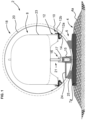
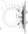
- a vacuum tube railway system 2 comprises a magnetic levitation railway vehicle 8, a vacuum tube 18 within which the railway vehicle 8 is guided, and a ground support 4 on which the vacuum tube 18 is supported.
- the ground support may have a ballasted surface 4a, in other words comprising gravel and/or stones, or may have an unballasted surface of concrete, asphalt, or other man-made surface (not shown).
- the vacuum tube railway system further comprises a magnetic levitation railway track 10 mounted inside the vacuum tube 18 for guiding the magnetic levitation railway vehicle 8 having corresponding levitation guide devices cooperating with the magnetic levitation rail 12.
- the magnetic levitation rail 12 comprises a support rail 12a that supports the weight of the railway vehicle in a contactless manner during displacement of the vehicle by magnetic levitation forces as per se known in the art of magnetic levitation vehicles.
- the magnetic levitation rail 12 may further comprise a guide rail 12b to laterally position the railway vehicle.
- Various other configurations are possible, such as an oblique levitation rail that functions to both laterally guide and vertically support the weight of the vehicle, or to have the lateral guide separate from the weight support rail.
- Coupling brackets 14 fix the magnetic levitation rail 12 to an inside of a wall 20 of the vacuum tube 18.
- the coupling brackets may have position adjustment mechanisms (not shown) to accurately position the magnetic levitation railway tracks with respect to each other and with respect to a linear motor 16 in order to accurately guide the railway vehicle along the vacuum tube 18.
- the railway system tubes further comprises a linear motor 16 comprising a stator 17 mounted in the vacuum tube 18, and a complementary mobile element 19 mounted on the railway vehicle 8 that magnetically couples to the stator 19 for driving the railway vehicle along the track 10.
- the stator may be mounted to the vacuum tube wall 20 via a coupling bracket 15 allowing to adjust the position of the stator 17 relative to the magnetic levitation rails and the railway vehicle for accurate coupling thereto.
- the stator 17 may typically comprise coils, for instance mounted in a ferromagnetic armature, generating a magnetic field that interacts with permanent magnets or an inductive mass in the mobile element 19. In embodiments it is also possible to have an ironless stator which means that the coils are not mounted on a ferromagnetic material.
- linear motors that are suitable for a magnetic levitation railway track are per se well-known and do not need to be further described herein.
- the linear motor may also be integrated in the magnetic levitation rails instead of being provided separately as illustrated, such configurations also being per se known in the art.
- a maintenance platform 24 may be provided for maintenance workers to travel within the tube during maintenance operations.
- the vacuum tube 18 preferably comprises a cylindrical or substantially cylindrical wall 20 however other cross-sectional profiles such as polygonal, square, elliptical, oval, or other non-axisymmetric shapes may be provided without departing from the scope of the claims.
- a cylindrical shaped (i.e. circular cross-section) vacuum tube 18 is however in many applications likely to be the simplest, most robust shape.
- the vacuum tube 18 may be made of sections of tube that may be prefabricated components each having a length allowing transport by rail or road.
- a section of tube may have a length in a range of 8 to 40 meters, the sections of tube being assembled one after the other along the ground support 4.
- Typical lengths for such tube segments are at least twice the diameter up to even 10 times of diameter of the tube, so for diameter of 4 meters the segments may be from 8 up to 40 meters.
- tube sections are preferably in a range of 12-16 meters long.
- the sections of a tube may be manufactured on site or close to the railway track, for instance by casting concrete around a reinforcement armature.
- casting machines which for instance moving along rails to place reinforcement and cast concrete using forms or molds.
- Another on site tube manufacturing method comprises manufacturing on the side of the track using a stationary casting machine which produces segments which are then transported to specified parts of the track where they are mounted.
- the material of the vacuum tube wall may comprise or consist of concrete, steel, or composite reinforced materials, and combinations of the foregoing.
- the sections of the vacuum tube 18 may be mounted on an existing or newly laid ground support.
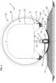
- the existing ground support may be designed for conventional railway vehicles, and may have rails for wheel railway vehicles as shown in figure 3 , or without rails (for instance by removing the rails prior to installation of the vacuum tube) as shown in figures 1 and 2 .
- a tube-support interface 25 may be mounted between a fabricated support 7 such as sleepers 7a or transverse beams 7b mounted on the ballasted surface 4a, and the tube, to conform to the shape of the tube and accurately position the tube on the ground support.
- the tube-support interface may comprise support beams or blocks 25 that may be positioned individually on railway sleepers or extending longitudinally over two or more railways sleepers.
- the support beams or blocks are configured to conform to the outer shape of the bottom portion of the vacuum tube to securely the position of the vacuum tube with respect to the ground support 4.
- the support beams or blocks may be made of separate parts from the sleeper 6 and fastened thereto and may further comprise a compliant, elastomeric, or deformable layer to spread the pressure of the vacuum tube on the support beam as well as optionally damping the coupling between the vacuum tube and ground to reduce vibration and noise when a railway vehicle is running along the magnetic levitation railway track.
- transverse beams 7b in addition to sleepers may be installed in the ballasted ground between sleepers and may further comprise support posts 11 that are buried and anchored into the ballasted ground support to support the transverse beams 7b.
- Such transverse beams 7b with support posts 11 may also be used to raise the railway tube over obstacles or to bridge across troughs.
- the vacuum tube 18 may also be positioned on existing railway tracks for conventional wheel railway vehicles.
- a compliant, elastic or plastically deformable spacer 29 or material may be positioned on the railway tracks in order to spread the contact pressure between the railway tracks and the vacuum tube and optionally to reduce vibration and noise when a railway vehicle is running inside the tube.
- the deformable spacer 29 may for instance be made of rubber or other elastomeric material, preferably reinforced with metal or composite wires or fibres.
- the deformable spacer may be supplied in linear segments of for instance at least 2m up to for instance 100m for laying on the steel rail 12 prior to lowering the sections of tube on to the rails.
- the tube-support interface in this embodiment may further comprise position ribs 27 for positioning and stabilization of the tube 18 on the rails 21.
- the ribs are configured to engage outer lateral edges of the steel rails 21.
- the positioning ribs may be fixed to the tube 18 in different manners depending on the material the tube wall 20 is made of, for instance by welding, adhesive bonding (e.g. Methyl methacrylate (MMA) adhesive or resin-based adhesive), or mounted using screws or anchors (in concrete).
- MMA Methyl methacrylate
- the ribs may be mounted in spacings for instance not less than 0,5m, whereby for straight sections of vacuum tube 18 shielded from wind the spacing may be even up to 6-12 meters.
- the vacuum tube may also be directly mounted on ballasted support without sleepers or with the sleepers of a conventional existing railway track having been removed.
- a compliant, elastomeric, or plastically deformable layer of material is cast, or positioned as a mat between the contact surface portion of the vacuum tube and the ground support.
- the material well adapted for the latter function may include various elastomers and rubbers, polyethylene, bitumen, geotextiles or combinations of these materials.
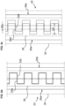
- Figure 5a shows longitudinal sectional view (i.e. along a direction parallel to a centerline of the vacuum tube) of a joining interface between two assembled sections of tube.
- Figures 5b and 5c are top views of a portion of a dilatation joint of the interface in a developed (i.e. flat) state.
- the vacuum tubes are provided in sections of typically between 8 to 40 meters long and thus have an interface between pre-fabricated or in situ manufactured sections. Certain interfaces may be bonded together in a substantially rigid hermetic manner to form longer sections (e.g. 16 to 80 meters) that are coupled together via an interface configured to allow thermal dilatation and contraction of the tube 18 relative to the ground support 4 on which the tubes are mounted. It is necessary to be able to adjust for some dilatation between at least some sections of the tubes, not necessarily between every section but at regular intervals depending on the type of ground, and the variation in diurnal or seasonal temperatures in the location of the installation.
- a dilatation joint 22 is mounted on the outside of the wall 20 of the vacuum tube 20, encircling the interface.
- the dilatation joint ensures a hermetic sealing of the inside of the vacuum tube 18 while allowing a specified maximum amount of dilatation between adjacent sections of tube 18.
- the dilatation joint comprises at least first and second support plates 26a, 26b a first support plate 26a being coupled to a first section of vacuum tube 18a, and a second support plate 26b being coupled to a second section of the vacuum tube 18b assembled to the first section.
- the support plates 26a, 26b may advantageously be made of a metal sheet for instance of copper, aluminium or steel sheet.
- the support plates 26a, 26b may also be made of a durable polymer such as High-density polyethylene (HDPE), or of a composite material, that is bonded, welded, riveted, or screwed to the corresponding section of tube in a manner to overlap the maximum interface between the juxtaposed end sections of tubes that are subject to dilatation.
- the support plates are bonded with an adhesive layer 33 to the outer surface of the tube wall 20.
- the support plates may be provided with interengaging fingers 32a, 32b having a length L1 that is greater than the maximum specified gap G subject to dilatation movements between the tubes 18a, 18b.
- the longitudinal length L1 of the fingers is thus greater than the maximum dilatation gap G for the range of operation of the vacuum tube 18.
- the support plate may for instance be made of a ductile material such as copper or HDPE that can be easily formed and bonded to the outside of the vacuum tube wall 20 during installation of the vacuum tube sections in situ.
- the support plates may be provided without interengaging fingers, but are in an overlapping relationship, the length of the maximum overlap being greater than the maximum dilatation gap G.
- a sealing membrane 28 may be positioned over the support plates 26a, 26b, and in particular over the interface between the support plates such that the sealing membrane 28 extends across the dilatation gap G and beyond.
- the sealing membrane may advantageously comprise a very elastic polymer material such as polyurea that is capable of elastic strain in excess of 100%, for instance up to 1000%. Other sealing materials such as Methyl methacrylate (MMA) may be used.
- the sealing membrane may comprise a multi-layer multi-material structure, for instance an underlaying primary sealing layer made for instance of a rubber layer bonded on the outer wall, or heat shrink polymer layer, and an outer coating of a sprayed or deposited layer of elastomeric material such as polyurea or MMA.
- the sealing membrane 28 covers the joint between the support plates and allows one or more sealing materials 30 to be cast, sprayed, injected, deposited or otherwise formed over the support plates 26a, 26b while preventing said sealing material from entering the gap between the support plates and from entering the gap between the ends of the walls 20.
- the support plates thus remain slidable with respect to each other over the maximum dilatation distance.
- the sealing layer 30 extends longitudinally over both ends of the respective support plates 26a, 26b and is in contact with the outer surface of the wall 20 of the vacuum tube of both sections 18a, 18b so as to provide a sealing around the support plates and sealing membrane 28.
- the difference in pressure between the outside of the vacuum tube and the inside creates pressure on the sealing layer 30 against the outside of the vacuum tube wall 20 to ensure a hermetic sealing.
- the substantially rigid support plates 26a, 26b maintain the rigidity of the sealing membrane across the maximum dilatation gap G to ensure that the vacuum tube sections 18a, 18b can move longitudinally with respect to each other without material being inserted in the dilatation gap that could get pinched therebetween to block further movement.
- the support plates that extend across the dilatation gap on the outer surface of the vacuum tubes ensure that the dilatation gap remains free of material and can move freely over the maximum specified dilatation distance G.
Landscapes
- Engineering & Computer Science (AREA)
- Mechanical Engineering (AREA)
- Architecture (AREA)
- Civil Engineering (AREA)
- Structural Engineering (AREA)
- Transportation (AREA)
- Physics & Mathematics (AREA)
- Electromagnetism (AREA)
- Control Of Vehicles With Linear Motors And Vehicles That Are Magnetically Levitated (AREA)
- Railway Tracks (AREA)
- Joints Allowing Movement (AREA)
Claims (15)
- Système de chemin de fer à tube à vide comprenant un tube à vide (18) monté sur un support au sol (4), une voie de chemin de fer à sustentation magnétique (10) montée à l'intérieur d'une paroi (20) formant le tube à vide (18) pour guider un véhicule ferroviaire à sustentation magnétique (8), le tube à vide (18) étant assemblé en sections le long du support au sol, au moins certaines parmi une pluralité de sections de tube à vide étant couplées les unes aux autres par un joint de dilatation (22) conçu pour sceller hermétiquement un espace de dilatation entre lesdites sections de tube, caractérisé en ce que le joint de dilatation (22) comprend au moins des première et deuxièmes plaques de support (26a, 26b) montées sur une surface externe de la paroi de tube (20), une première plaque de support étant fixée à une première section (18a) du tube à vide et une deuxième plaque de support (26b) étant fixée à une deuxième section (18b) du tube à vide, les plaques de support s'étendant longitudinalement sur l'espace de dilatation sur une longueur (L1) supérieure à un espace de dilatation maximale (G), les première et deuxième plaques de support étant montées de manière coulissante l'une par rapport à l'autre, le joint de dilatation comprenant en outre une couche d'étanchéité élastique (30) s'étendant sur un côté externe des plaques de support, la couche d'étanchéité étant liée à la surface extérieure de la paroi et s'étendant complètement sur les plaques de support, en étant conçue pour sceller hermétiquement l'espace de dilatation lorsque la pression à l'intérieur du tube à vide est inférieure à la pression atmosphérique.
- Système de chemin de fer à tube à vide selon la revendication précédentes, dans lequel le joint de dilatation (22) comprend en outre une membrane d'étanchéité (28) s'étendant sur un côté extérieur des plaques de support (26a, 26b) sur une longueur longitudinale supérieure à l'espace de dilatation maximale, en étant configurée pour empêcher le matériau de la couche d'étanchéité (30) d'entrer dans un espace entre lesdites plaques de support et ledit espace de dilatation.
- Système de chemin de fer à tube à vide selon l'une quelconque des revendications précédentes, dans lequel la couche d'étanchéité est faite d'un matériau élastomère déposé à l'état fluide in situ par un procédé de déposition comprenant l'une quelconque ou plusieurs parmi une pulvérisation, une injection, et une déposition avec des outils de déposition en couche tels qu'une brosse ou une spatule.
- Système de chemin de fer à tube à vide selon la revendication 2, dans lequel le joint de dilatation (22) peut en outre comprendre une feuille ou bande de matériau élastomère tel qu'un caoutchouc, qui est assemblée sur le dessus des plaques de support avant la déposition de la membrane d'étanchéité (28).
- Système de chemin de fer à tube à vide selon la revendication 2 ou 4, dans lequel la membrane d'étanchéité peut consister en ou comprendre un polymère élastomère englobant l'un quelconque ou plusieurs parmi une polyurée, le méthacrylate de méthyle (MMA), un caoutchouc de nitrile-butadiène hydrogéné (HNBR), et un caoutchouc siliconé fluoré (FVMQ), ainsi que les polymères élastomères à base de silicone.
- Système de chemin de fer à tube à vide selon la revendication 2, 4 ou 5, dans lequel la membrane d'étanchéité (28) est faite d'une feuille ou bande d'un polymère englobant l'un quelconque ou plusieurs parmi une polyurée, le méthacrylate de méthyle (MMA), un caoutchouc de nitrile-butadiène hydrogéné (HNBR), et un caoutchouc siliconé fluoré (FVMQ), ainsi que les polymères élastomères à base de silicone.
- Système de chemin de fer à tube à vide selon l'une quelconque des revendications précédentes, dans lequel les plaques de support (26a, 26b) sont faites d'une feuille de métal, de HDPE, ou d'un matériau en résine époxy renforcée par des fibres.
- Système de chemin de fer à tube à vide selon l'une quelconque des revendications précédentes, dans lequel les plaques de support sont attachées à la paroi (20) de la section de tube à vide correspondante par un collage adhésif (33) .
- Système de chemin de fer à tube à vide selon l'une quelconque des revendications précédentes, dans lequel les plaques de support se présentent sous la forme de segments linéaires plats pliables, par exemple de l'ordre de 2 à 15 mètres ou plus, pour un assemblage à la surface extérieure de la paroi de tube par conformation flexible au profil en coupe transversale du tube.
- Système de chemin de fer à tube à vide selon l'une quelconque des revendications précédentes, dans lequel les plaques de support (26a, 26b) ont des dents en engagement mutuel (32a, 32b), la longueur (L1) des dents étant supérieure à l'espace de dilation maximale (G).
- Système de chemin de fer à tube à vide selon l'une quelconque des revendications précédentes, dans lequel les plaques de support se chevauchent les unes les autres à travers l'espace de dilatation et sur une distance de chevauchement supérieure à l'espace de dilatation maximale (G).
- Système de chemin de fer à tube à vide selon l'une quelconque des revendications précédentes, dans lequel le tube à vide est fait de sections ayant une longueur comprise entre 8 et 40 mètres, et dans lequel le tube à vide est fait de sections transportables préfabriquées ayant une longueur comprise entre 8 et 18 mètres, de préférence une longueur comprise entre 12 et 16 mètres, ou dans lequel le tube à vide est fabriqué in situ en sections ayant une longueur comprise entre 12 et 40 mètres, de préférence une longueur comprise entre 20 et 40 mètres.
- Système de chemin de fer à tube à vide selon l'une quelconque des revendications précédentes, dans lequel les sections de tube à vide sont montées sur un support au sol d'une voie de chemin de fer conventionnelle existante ayant une surface ballastée (4a), et dans lequel : les sections de tube à vide sont montées sur des rails en acier existants (21), comprenant en outre une entretoise déformable (29) montée entre le rail en acier (21) et la paroi (20) du tube à vide ; ou bien les sections de tube à vide sont montées directement sur la surface ballastée, un mat déformable (31) étant positionné entre la surface ballastée et la paroi du tube ; ou bien les sections de tube sont montées sur des traverses de chemin de fer existantes (7a) d'une voie de chemin de fer conventionnelle dans laquelle les rails en acier ont été retirés, des poutres ou blocs de support (25) étant montés entre les traverses et la paroi de tube.
- Système de chemin de fer à tube à vide selon la revendication immédiatement précédente, comprenant en outre une nervure de positionnement (27) fixée à un côté extérieur de la paroi (20) du tube à vide et s'engageant avec un côté latéral extérieur du rail en acier (21).
- Système de chemin de fer à tube à vide selon l'une quelconque des revendications précédentes, comprenant en outre un moteur linéaire (16) comprenant un stator (17) monté via une console de couplage (15) à un côté intérieur de la paroi de tube à vide.
Applications Claiming Priority (2)
| Application Number | Priority Date | Filing Date | Title |
|---|---|---|---|
| PL429274A PL244786B1 (pl) | 2019-03-14 | 2019-03-14 | Sposób przekształcenia torowiska kolei konwencjonalnej typu koło-szyna lub magnetycznej kolei zintegrowanej na system próżniowy kolei magnetycznej |
| PCT/EP2020/057011 WO2020183027A1 (fr) | 2019-03-14 | 2020-03-14 | Système de chemin de fer à tube à vide |
Publications (3)
| Publication Number | Publication Date |
|---|---|
| EP3938577A1 EP3938577A1 (fr) | 2022-01-19 |
| EP3938577C0 EP3938577C0 (fr) | 2023-06-07 |
| EP3938577B1 true EP3938577B1 (fr) | 2023-06-07 |
Family
ID=69903123
Family Applications (1)
| Application Number | Title | Priority Date | Filing Date |
|---|---|---|---|
| EP20712885.1A Active EP3938577B1 (fr) | 2019-03-14 | 2020-03-14 | Système de chemin de fer à tube à vide |
Country Status (15)
| Country | Link |
|---|---|
| US (1) | US11346059B2 (fr) |
| EP (1) | EP3938577B1 (fr) |
| JP (1) | JP7155442B2 (fr) |
| CN (1) | CN113994048B (fr) |
| AU (1) | AU2020239368B2 (fr) |
| BR (1) | BR112021018143A2 (fr) |
| CA (1) | CA3133382C (fr) |
| EA (1) | EA202192332A1 (fr) |
| IL (1) | IL286246B (fr) |
| MA (1) | MA55292A (fr) |
| MX (1) | MX2021011065A (fr) |
| PL (2) | PL244786B1 (fr) |
| SA (1) | SA521430331B1 (fr) |
| WO (1) | WO2020183027A1 (fr) |
| ZA (1) | ZA202106921B (fr) |
Families Citing this family (10)
| Publication number | Priority date | Publication date | Assignee | Title |
|---|---|---|---|---|
| ES2827898B2 (es) * | 2019-10-08 | 2025-02-12 | Zeleros Global S L | Sistema matricial de suspension electromagnetica para vehiculos de transporte |
| CN111277109B (zh) * | 2020-03-11 | 2021-02-23 | 中车青岛四方机车车辆股份有限公司 | 一种磁浮列车直线电机及一种磁浮列车 |
| KR102386207B1 (ko) * | 2020-06-08 | 2022-04-13 | 주식회사 포스코 | 가이드튜브 및 이를 포함하는 하이퍼루프장치 |
| ES2808729B2 (es) * | 2020-12-23 | 2021-07-07 | Univ Valencia Politecnica | Estructura tubular portatil y estructura tubular fija derivada de ella |
| CN112849166B (zh) * | 2021-01-15 | 2022-05-20 | 中铁工程设计咨询集团有限公司 | 一种真空磁悬浮管道的梁部构造及真空磁悬浮管道 |
| CN114789737B (zh) * | 2022-04-28 | 2023-06-27 | 中铁第四勘察设计院集团有限公司 | 一种真空磁浮管道结构 |
| CN115217025A (zh) * | 2022-07-01 | 2022-10-21 | 中铁第四勘察设计院集团有限公司 | 一种磁浮管道桥 |
| CN115305801B (zh) * | 2022-07-01 | 2026-03-06 | 中铁第四勘察设计院集团有限公司 | 一种磁浮管道桥 |
| KR20240035118A (ko) * | 2022-09-08 | 2024-03-15 | 주식회사 포스코 | 튜브진동 감쇠구조 |
| US12103569B2 (en) * | 2023-01-31 | 2024-10-01 | Tsunami Energy Enterprise Pty Ltd | Vacuum pipeline magnetic levitation conveying device |
Family Cites Families (18)
| Publication number | Priority date | Publication date | Assignee | Title |
|---|---|---|---|---|
| US2452057A (en) * | 1946-05-21 | 1948-10-26 | James W Kehoe | Flexible leakproof coupling |
| FR2238802B1 (fr) | 1973-07-27 | 1976-04-30 | Sncf | |
| US4067534A (en) * | 1976-09-20 | 1978-01-10 | Celanese Corporation | Pipe coupler assembly |
| US4119334A (en) * | 1977-07-01 | 1978-10-10 | Fafco Incorporated | Spinwelded plastic pipe coupling joint |
| JPS5727992Y2 (fr) * | 1978-04-18 | 1982-06-18 | ||
| US6402203B1 (en) * | 2000-09-15 | 2002-06-11 | Senior Investments Ag | Flange construction for fabric expansion joints |
| CN101427063A (zh) * | 2004-03-26 | 2009-05-06 | 维克托里克公司 | 具有楔形圆周槽的管道 |
| KR101130807B1 (ko) | 2009-12-17 | 2012-03-28 | 한국철도기술연구원 | 튜브 철도 시스템의 진공 분할 관리 시스템 및 진공 차단막 장치 |
| KR101670907B1 (ko) * | 2015-01-29 | 2016-10-31 | 권두영 | 상하수관용 연결 구조체 |
| EP3253636B1 (fr) | 2015-02-08 | 2021-05-12 | Hyperloop Technologies, Inc. | Système de transport |
| US10533688B2 (en) * | 2016-05-16 | 2020-01-14 | Victaulic Company | Coupling having tabbed retainer |
| ES2915904T3 (es) * | 2016-11-23 | 2022-06-27 | Hyperloop Tech Inc | Estructura encerrada modular de transporte y montaje de pista integrada |
| KR101830638B1 (ko) | 2016-12-12 | 2018-02-21 | 한국건설기술연구원 | 초고속 튜브철도용 튜브 쉴드와 콘크리트 슬래브구조체를 일체화시킨 튜브 구조물 및 그 시공 방법 |
| US10982798B2 (en) * | 2017-07-07 | 2021-04-20 | Mueller Industries, Inc. | Press-connect fitting with membrane seal |
| CN107882829B (zh) * | 2017-10-11 | 2020-12-08 | 西南交通大学 | 一种多向联动真空管道气密性伸缩装置 |
| KR101853924B1 (ko) | 2017-11-21 | 2018-05-02 | 한국건설기술연구원 | 초고속 튜브철도용 종방향 신축이음장치를 구비한 슬래브-캐노피 합성모듈형 운송관 구조물 및 그 시공방법 |
| CN108327733A (zh) * | 2018-03-08 | 2018-07-27 | 沈明横 | 一种高速轨道列车运输系统 |
| KR102122076B1 (ko) * | 2018-05-21 | 2020-06-26 | 한국철도기술연구원 | 하이퍼튜브용 실링장치 |
-
2019
- 2019-03-14 PL PL429274A patent/PL244786B1/pl unknown
-
2020
- 2020-03-14 PL PL20712885.1T patent/PL3938577T3/pl unknown
- 2020-03-14 MA MA055292A patent/MA55292A/fr unknown
- 2020-03-14 US US17/438,191 patent/US11346059B2/en active Active
- 2020-03-14 BR BR112021018143A patent/BR112021018143A2/pt not_active Application Discontinuation
- 2020-03-14 CA CA3133382A patent/CA3133382C/fr active Active
- 2020-03-14 EA EA202192332A patent/EA202192332A1/ru unknown
- 2020-03-14 CN CN202080031537.8A patent/CN113994048B/zh not_active Expired - Fee Related
- 2020-03-14 AU AU2020239368A patent/AU2020239368B2/en not_active Ceased
- 2020-03-14 JP JP2021555391A patent/JP7155442B2/ja active Active
- 2020-03-14 MX MX2021011065A patent/MX2021011065A/es unknown
- 2020-03-14 EP EP20712885.1A patent/EP3938577B1/fr active Active
- 2020-03-14 WO PCT/EP2020/057011 patent/WO2020183027A1/fr not_active Ceased
-
2021
- 2021-09-09 IL IL286246A patent/IL286246B/en unknown
- 2021-09-13 SA SA521430331A patent/SA521430331B1/ar unknown
- 2021-09-17 ZA ZA2021/06921A patent/ZA202106921B/en unknown
Also Published As
| Publication number | Publication date |
|---|---|
| CA3133382C (fr) | 2022-06-14 |
| IL286246B (en) | 2022-04-01 |
| JP2022518969A (ja) | 2022-03-17 |
| AU2020239368B2 (en) | 2021-11-11 |
| SA521430331B1 (ar) | 2022-11-17 |
| EP3938577C0 (fr) | 2023-06-07 |
| EA202192332A1 (ru) | 2021-10-28 |
| MA55292A (fr) | 2022-01-19 |
| CA3133382A1 (fr) | 2020-09-17 |
| WO2020183027A1 (fr) | 2020-09-17 |
| BR112021018143A2 (pt) | 2021-11-16 |
| PL3938577T3 (pl) | 2024-01-03 |
| US20220042249A1 (en) | 2022-02-10 |
| MX2021011065A (es) | 2021-12-15 |
| ZA202106921B (en) | 2022-08-31 |
| EP3938577A1 (fr) | 2022-01-19 |
| CN113994048A (zh) | 2022-01-28 |
| PL429274A1 (pl) | 2020-09-21 |
| US11346059B2 (en) | 2022-05-31 |
| PL244786B1 (pl) | 2024-03-04 |
| CN113994048B (zh) | 2022-12-02 |
| IL286246A (en) | 2021-10-31 |
| JP7155442B2 (ja) | 2022-10-18 |
Similar Documents
| Publication | Publication Date | Title |
|---|---|---|
| AU2020239368B2 (en) | Vacuum tube railway system | |
| EP2529050B1 (fr) | Support de voie de chemin de fer ou métro | |
| EP3841249B1 (fr) | Système de voie ferrée à lévitation magnétique | |
| CN108914713A (zh) | 用于减振地段的无砟轨道的湿接式装配方法 | |
| HK40067783A (en) | Vacuum tube railway system | |
| HK40067783B (en) | Vacuum tube railway system | |
| EA006338B1 (ru) | Фиксированный путь для рельсового транспорта и способ его изготовления | |
| CA2477887A1 (fr) | Structure de voie ferree sans ballast et traverse associee | |
| KR101510833B1 (ko) | 콘크리트가 충진된 강관 직결 궤도 및 그 시공 방법 | |
| KR101161628B1 (ko) | 레일체결구가 부착된 거더 철도교량 | |
| WO2021117056A1 (fr) | Voie non ballastée à ancrage mécanique dotée d'un système de fixation élastique continu | |
| EA040462B1 (ru) | Железнодорожная система типа "вакуумная труба" | |
| EP1904683B1 (fr) | Procédé et système pour la fixation de voie ferrée | |
| US20250230611A1 (en) | Track | |
| KR101982567B1 (ko) | 종방향 슬립을 허용하는 강철도교용 무도상궤도 구조 | |
| EP1775381A1 (fr) | Procédé pour le renouvellement de voies ferrées en tunnel | |
| KR20190102404A (ko) | 슬라이딩 수지고정궤도구조 | |
| EA043955B1 (ru) | Железнодорожная система на магнитной подушке | |
| WO2012076891A1 (fr) | Poutre de support de rail |
Legal Events
| Date | Code | Title | Description |
|---|---|---|---|
| STAA | Information on the status of an ep patent application or granted ep patent |
Free format text: STATUS: UNKNOWN |
|
| STAA | Information on the status of an ep patent application or granted ep patent |
Free format text: STATUS: THE INTERNATIONAL PUBLICATION HAS BEEN MADE |
|
| PUAI | Public reference made under article 153(3) epc to a published international application that has entered the european phase |
Free format text: ORIGINAL CODE: 0009012 |
|
| STAA | Information on the status of an ep patent application or granted ep patent |
Free format text: STATUS: REQUEST FOR EXAMINATION WAS MADE |
|
| 17P | Request for examination filed |
Effective date: 20211012 |
|
| AK | Designated contracting states |
Kind code of ref document: A1 Designated state(s): AL AT BE BG CH CY CZ DE DK EE ES FI FR GB GR HR HU IE IS IT LI LT LU LV MC MK MT NL NO PL PT RO RS SE SI SK SM TR |
|
| DAX | Request for extension of the european patent (deleted) | ||
| RAV | Requested validation state of the european patent: fee paid |
Extension state: TN Effective date: 20211012 Extension state: MA Effective date: 20211012 |
|
| GRAP | Despatch of communication of intention to grant a patent |
Free format text: ORIGINAL CODE: EPIDOSNIGR1 |
|
| STAA | Information on the status of an ep patent application or granted ep patent |
Free format text: STATUS: GRANT OF PATENT IS INTENDED |
|
| REG | Reference to a national code |
Ref country code: HK Ref legal event code: DE Ref document number: 40067783 Country of ref document: HK |
|
| INTG | Intention to grant announced |
Effective date: 20220905 |
|
| GRAS | Grant fee paid |
Free format text: ORIGINAL CODE: EPIDOSNIGR3 |
|
| GRAA | (expected) grant |
Free format text: ORIGINAL CODE: 0009210 |
|
| STAA | Information on the status of an ep patent application or granted ep patent |
Free format text: STATUS: THE PATENT HAS BEEN GRANTED |
|
| AK | Designated contracting states |
Kind code of ref document: B1 Designated state(s): AL AT BE BG CH CY CZ DE DK EE ES FI FR GB GR HR HU IE IS IT LI LT LU LV MC MK MT NL NO PL PT RO RS SE SI SK SM TR |
|
| REG | Reference to a national code |
Ref country code: GB Ref legal event code: FG4D |
|
| REG | Reference to a national code |
Ref country code: CH Ref legal event code: EP Ref country code: AT Ref legal event code: REF Ref document number: 1575331 Country of ref document: AT Kind code of ref document: T Effective date: 20230615 Ref country code: DE Ref legal event code: R096 Ref document number: 602020011941 Country of ref document: DE |
|
| U01 | Request for unitary effect filed |
Effective date: 20230705 |
|
| U07 | Unitary effect registered |
Designated state(s): AT BE BG DE DK EE FI FR IT LT LU LV MT NL PT SE SI Effective date: 20230717 |
|
| REG | Reference to a national code |
Ref country code: LT Ref legal event code: MG9D |
|
| PG25 | Lapsed in a contracting state [announced via postgrant information from national office to epo] |
Ref country code: NO Free format text: LAPSE BECAUSE OF FAILURE TO SUBMIT A TRANSLATION OF THE DESCRIPTION OR TO PAY THE FEE WITHIN THE PRESCRIBED TIME-LIMIT Effective date: 20230907 Ref country code: ES Free format text: LAPSE BECAUSE OF FAILURE TO SUBMIT A TRANSLATION OF THE DESCRIPTION OR TO PAY THE FEE WITHIN THE PRESCRIBED TIME-LIMIT Effective date: 20230607 |
|
| PG25 | Lapsed in a contracting state [announced via postgrant information from national office to epo] |
Ref country code: RS Free format text: LAPSE BECAUSE OF FAILURE TO SUBMIT A TRANSLATION OF THE DESCRIPTION OR TO PAY THE FEE WITHIN THE PRESCRIBED TIME-LIMIT Effective date: 20230607 Ref country code: HR Free format text: LAPSE BECAUSE OF FAILURE TO SUBMIT A TRANSLATION OF THE DESCRIPTION OR TO PAY THE FEE WITHIN THE PRESCRIBED TIME-LIMIT Effective date: 20230607 Ref country code: GR Free format text: LAPSE BECAUSE OF FAILURE TO SUBMIT A TRANSLATION OF THE DESCRIPTION OR TO PAY THE FEE WITHIN THE PRESCRIBED TIME-LIMIT Effective date: 20230908 |
|
| PG25 | Lapsed in a contracting state [announced via postgrant information from national office to epo] |
Ref country code: SK Free format text: LAPSE BECAUSE OF FAILURE TO SUBMIT A TRANSLATION OF THE DESCRIPTION OR TO PAY THE FEE WITHIN THE PRESCRIBED TIME-LIMIT Effective date: 20230607 |
|
| PG25 | Lapsed in a contracting state [announced via postgrant information from national office to epo] |
Ref country code: IS Free format text: LAPSE BECAUSE OF FAILURE TO SUBMIT A TRANSLATION OF THE DESCRIPTION OR TO PAY THE FEE WITHIN THE PRESCRIBED TIME-LIMIT Effective date: 20231007 |
|
| PG25 | Lapsed in a contracting state [announced via postgrant information from national office to epo] |
Ref country code: SM Free format text: LAPSE BECAUSE OF FAILURE TO SUBMIT A TRANSLATION OF THE DESCRIPTION OR TO PAY THE FEE WITHIN THE PRESCRIBED TIME-LIMIT Effective date: 20230607 Ref country code: SK Free format text: LAPSE BECAUSE OF FAILURE TO SUBMIT A TRANSLATION OF THE DESCRIPTION OR TO PAY THE FEE WITHIN THE PRESCRIBED TIME-LIMIT Effective date: 20230607 Ref country code: RO Free format text: LAPSE BECAUSE OF FAILURE TO SUBMIT A TRANSLATION OF THE DESCRIPTION OR TO PAY THE FEE WITHIN THE PRESCRIBED TIME-LIMIT Effective date: 20230607 Ref country code: IS Free format text: LAPSE BECAUSE OF FAILURE TO SUBMIT A TRANSLATION OF THE DESCRIPTION OR TO PAY THE FEE WITHIN THE PRESCRIBED TIME-LIMIT Effective date: 20231007 Ref country code: CZ Free format text: LAPSE BECAUSE OF FAILURE TO SUBMIT A TRANSLATION OF THE DESCRIPTION OR TO PAY THE FEE WITHIN THE PRESCRIBED TIME-LIMIT Effective date: 20230607 |
|
| REG | Reference to a national code |
Ref country code: DE Ref legal event code: R097 Ref document number: 602020011941 Country of ref document: DE |
|
| PLBE | No opposition filed within time limit |
Free format text: ORIGINAL CODE: 0009261 |
|
| STAA | Information on the status of an ep patent application or granted ep patent |
Free format text: STATUS: NO OPPOSITION FILED WITHIN TIME LIMIT |
|
| U20 | Renewal fee for the european patent with unitary effect paid |
Year of fee payment: 5 Effective date: 20240328 |
|
| 26N | No opposition filed |
Effective date: 20240308 |
|
| REG | Reference to a national code |
Ref country code: CH Ref legal event code: PL |
|
| PG25 | Lapsed in a contracting state [announced via postgrant information from national office to epo] |
Ref country code: MC Free format text: LAPSE BECAUSE OF FAILURE TO SUBMIT A TRANSLATION OF THE DESCRIPTION OR TO PAY THE FEE WITHIN THE PRESCRIBED TIME-LIMIT Effective date: 20230607 |
|
| GBPC | Gb: european patent ceased through non-payment of renewal fee |
Effective date: 20240314 |
|
| PG25 | Lapsed in a contracting state [announced via postgrant information from national office to epo] |
Ref country code: MC Free format text: LAPSE BECAUSE OF FAILURE TO SUBMIT A TRANSLATION OF THE DESCRIPTION OR TO PAY THE FEE WITHIN THE PRESCRIBED TIME-LIMIT Effective date: 20230607 |
|
| PG25 | Lapsed in a contracting state [announced via postgrant information from national office to epo] |
Ref country code: GB Free format text: LAPSE BECAUSE OF NON-PAYMENT OF DUE FEES Effective date: 20240314 |
|
| PG25 | Lapsed in a contracting state [announced via postgrant information from national office to epo] |
Ref country code: IE Free format text: LAPSE BECAUSE OF NON-PAYMENT OF DUE FEES Effective date: 20240314 |
|
| PG25 | Lapsed in a contracting state [announced via postgrant information from national office to epo] |
Ref country code: IE Free format text: LAPSE BECAUSE OF NON-PAYMENT OF DUE FEES Effective date: 20240314 Ref country code: GB Free format text: LAPSE BECAUSE OF NON-PAYMENT OF DUE FEES Effective date: 20240314 Ref country code: CH Free format text: LAPSE BECAUSE OF NON-PAYMENT OF DUE FEES Effective date: 20240331 |
|
| U20 | Renewal fee for the european patent with unitary effect paid |
Year of fee payment: 6 Effective date: 20250331 |
|
| PG25 | Lapsed in a contracting state [announced via postgrant information from national office to epo] |
Ref country code: CY Free format text: LAPSE BECAUSE OF FAILURE TO SUBMIT A TRANSLATION OF THE DESCRIPTION OR TO PAY THE FEE WITHIN THE PRESCRIBED TIME-LIMIT; INVALID AB INITIO Effective date: 20200314 |
|
| PG25 | Lapsed in a contracting state [announced via postgrant information from national office to epo] |
Ref country code: HU Free format text: LAPSE BECAUSE OF FAILURE TO SUBMIT A TRANSLATION OF THE DESCRIPTION OR TO PAY THE FEE WITHIN THE PRESCRIBED TIME-LIMIT; INVALID AB INITIO Effective date: 20200314 |
|
| PGFP | Annual fee paid to national office [announced via postgrant information from national office to epo] |
Ref country code: PL Payment date: 20250710 Year of fee payment: 6 |
|
| VS25 | Lapsed in a validation state [announced via postgrant information from nat. office to epo] |
Ref country code: MA Free format text: FAILURE TO ELECT DOMICILE IN THE NATIONAL COUNTRY Effective date: 20230908 |
|
| PG25 | Lapsed in a contracting state [announced via postgrant information from national office to epo] |
Ref country code: TR Free format text: LAPSE BECAUSE OF FAILURE TO SUBMIT A TRANSLATION OF THE DESCRIPTION OR TO PAY THE FEE WITHIN THE PRESCRIBED TIME-LIMIT Effective date: 20230607 |