EP3938579B1 - Appareil de purification d'air, tunnel routier comprenant ledit appareil de purification d'air et procédé de purification d'air - Google Patents
Appareil de purification d'air, tunnel routier comprenant ledit appareil de purification d'air et procédé de purification d'air Download PDFInfo
- Publication number
- EP3938579B1 EP3938579B1 EP20712706.9A EP20712706A EP3938579B1 EP 3938579 B1 EP3938579 B1 EP 3938579B1 EP 20712706 A EP20712706 A EP 20712706A EP 3938579 B1 EP3938579 B1 EP 3938579B1
- Authority
- EP
- European Patent Office
- Prior art keywords
- air
- air duct
- way valve
- roadside
- outlet
- Prior art date
- Legal status (The legal status is an assumption and is not a legal conclusion. Google has not performed a legal analysis and makes no representation as to the accuracy of the status listed.)
- Active
Links
Images



Classifications
-
- E—FIXED CONSTRUCTIONS
- E21—EARTH OR ROCK DRILLING; MINING
- E21B—EARTH OR ROCK DRILLING; OBTAINING OIL, GAS, WATER, SOLUBLE OR MELTABLE MATERIALS OR A SLURRY OF MINERALS FROM WELLS
- E21B1/00—Percussion drilling
-
- E—FIXED CONSTRUCTIONS
- E01—CONSTRUCTION OF ROADS, RAILWAYS, OR BRIDGES
- E01C—CONSTRUCTION OF, OR SURFACES FOR, ROADS, SPORTS GROUNDS, OR THE LIKE; MACHINES OR AUXILIARY TOOLS FOR CONSTRUCTION OR REPAIR
- E01C1/00—Design or layout of roads, e.g. for noise abatement, for gas absorption
- E01C1/005—Means permanently installed along the road for removing or neutralising exhaust gases
-
- E—FIXED CONSTRUCTIONS
- E01—CONSTRUCTION OF ROADS, RAILWAYS, OR BRIDGES
- E01F—ADDITIONAL WORK, SUCH AS EQUIPPING ROADS OR THE CONSTRUCTION OF PLATFORMS, HELICOPTER LANDING STAGES, SIGNS, SNOW FENCES, OR THE LIKE
- E01F15/00—Safety arrangements for slowing, redirecting or stopping errant vehicles, e.g. guard posts or bollards; Arrangements for reducing damage to roadside structures due to vehicular impact
- E01F15/02—Continuous barriers extending along roads or between traffic lanes
- E01F15/04—Continuous barriers extending along roads or between traffic lanes essentially made of longitudinal beams or rigid strips supported above ground at spaced points
-
- E—FIXED CONSTRUCTIONS
- E21—EARTH OR ROCK DRILLING; MINING
- E21F—SAFETY DEVICES, TRANSPORT, FILLING-UP, RESCUE, VENTILATION, OR DRAINING IN OR OF MINES OR TUNNELS
- E21F1/00—Ventilation of mines or tunnels; Distribution of ventilating currents
- E21F1/003—Ventilation of traffic tunnels
Definitions
- the invention relates to an air purifying apparatus, in particular a passive air purifying apparatus, for along the roadside.
- roadside air or polluted air comprises exhaust gases from traffic, such as greenhouse gases and particulate matter, which accumulate at and/or near the roadside.
- traffic such as greenhouse gases and particulate matter
- polluted air may linger in road tunnels. Therefore, in the vicinity of the roadside, environmental norms may be exceeded locally to the detriment of the environment and possibly to the health of road users and/or (local) residents.
- polluted air may tend to accumulate at the entrance/exit of the tunnel relatively quickly and may often exceed environmental norms. Polluted air accumulates in the tunnel and is driven towards the entrance/exit by traffic exiting the tunnel.
- a vehicle that participates in or makes up the traffic causes a local disturbance in an ambient pressure field. This local disturbance or change in the ambient pressure field around the vehicle moves along with the vehicle and tends to drive polluted air comprising e.g. exhaust gasses and/or particulate matter towards the end of the tunnel, that is to say the entrance/exit in case of two-way tunnels.
- Vehicles with a relatively large frontal surface area such as Sport Utility Vehicles (SUVs), busses, trucks and lorries, may relatively speaking contribute more to this phenomenon as they generally cause greater local changes in the pressure field around the vehicle than for instance cars or motorcycles. Consequently the aforementioned types of vehicles may cause a greater displacement of polluted air towards the end of the tunnel.
- SUVs Sport Utility Vehicles
- busses trucks and lorries
- Active air purifying devices are generally known and typically applied in road tunnels. Commonly, active air purifying devices are required for ventilating road tunnels of a certain length, e.g. tunnels of at least 500 m in the Netherlands. In particular, national legislation requires active ventilation in case of traffic jams, which may cause a relatively fast accumulation of polluted air within the road tunnel. Also, these active air purifying devices are often required to actively dissipate and/or lead away smoke in case of a fire within the road tunnel, e.g. for safety or evacuation purposes. Typically, these active air purifying devices comprise an inlet, an outlet, an air duct extending therebetween, and a power source to power one or more ventilators that are provided in and/or along the air duct.
- the invention aims at alleviating one or more of the aforementioned disadvantages.
- the invention aims to provide a passive air purifying apparatus that dissipates and/or disperses polluted air and does not require active ventilation. Thereby, the energy consumption and operational cost of the air purifying apparatus may be reduced with a relatively simple construction that may require low maintenance.
- the invention provides for a passive air purifying apparatus for along the roadside according to claim 1.
- An over-pressure in this context is an above-atmospheric pressure, wherein the atmospheric pressure is the environmental pressure prevailing at the roadside when no vehicles are passing.
- the over-pressure that is generated by a passing vehicle is meant to be construed as a local pressure increase in the flow field around the vehicle.
- a pressure accumulation at a side of the vehicle that faces the air flow that is incoming with respect to the vehicle For example, as the vehicle moves through the air, the air is pushed aside by the vehicle and thereby the air flows around the vehicle. Due to the inertia of the air its pressure may increase locally causing the so-called over-pressure at the side of the vehicle that faces the direction of travel of the vehicle.
- roadside air may be fed into the air duct through the at least one inlet using the over-pressure generated by a passing vehicle.
- roadside air that is relatively polluted with respect to ambient air, may passively be dispelled from the roadside and be fed into the air duct.
- the outlet When the outlet is positioned remote from the roadside, it may be facilitated that roadside air that has been fed into the air duct may be expelled and/or dispersed out of the air duct remote from the roadside. Thereby, locally exceeding environmental norms may be counteracted cost-effectively using a relatively simple construction.
- the one-way valve comprises a flap for actuating the one-way valve from the closed to an open position
- a construction that is relatively sensitive to over-pressure generated by passing vehicles may be achieved. This way, the flap may be used for actuating the one-way valve from the closed to an open position.
- the flap When the flap is connected to and/or forms part of a valve body which valve body engages a valve seat when being in the closed position, the valve body and/or flap may rest on the valve seat in the closed position.
- the valve seat may counteract that the valve body and/or flap moves past the valve seat toward the side of the one-way valve that faces away from the air duct.
- the flap may be configured for actuating the valve body to bring it from the closed to an open position.
- the flap may be aerodynamically shaped to tailor its response to over-pressure generated by passing vehicles.
- air in particular roadside air
- the at least one outlet may be transferred through the air duct to the external environment relatively effectively via the so-called stack-effect.
- pollutants may be dispersed remotely which may reduce their impact on the (immediate) surroundings. This way, exceeding environmental norms locally along the roadside may be counteracted further.
- pollutants may be dispersed at higher altitudes which may reduce their impact on the (immediate) surroundings.
- pollutants may be dispersed above the immediate surroundings, such as buildings or noise barriers. This may be especially beneficial in so-called street canyons in which a road or street is flanked by buildings on both sides creating a canyon-like environment.
- pollutants may be dispersed more effectively at higher altitudes where the so-called wind speed is generally higher relative to the wind speed at lower altitudes.
- the at least one outlet in particular comprising the flue
- the at least one outlet is configured for passively generating an under-pressure in the air duct
- passive transfer of roadside air from the at least one inlet to the at least one outlet via the air duct may be facilitated.
- the passive transfer of air may be facilitated using a relatively simple and cost-effective construction.
- a relatively large volume of air in particular roadside air, may be fed into the air duct via the plurality of interspaced inlets to be dispersed remote from the roadside, e.g. through the at least one outlet.
- the at least one air guiding panel placed along the air duct that guides the airflow generated by passing vehicles toward and/or through the at least one inlet, a momentum of airflow may be led towards and generate a pressure difference at the inlet.
- flow of air, in particular roadside air, towards and/or through the at least one inlet may be facilitated.
- dissipation of polluted air away from the roadside and into the air duct may be facilitated.
- the at least one air guiding panel may be provided and/or formed as a so-called air scoop.
- the passive air purifying apparatus comprises at least one second inlet, at least one second outlet and a second air duct connecting the at least one second inlet with the at least one second outlet, wherein the at least one second outlet is positioned along the roadside and wherein the at least one second inlet positioned remote from the roadside, wherein the at least one second outlet is provided with an opposite one-way valve that is also biased towards a closed position, wherein the bias is such that the opposite one-way valve opens when a second valve pressure difference between a side of the opposite one-way valve that faces away from the air duct and a side of the opposite one-way valve that faces towards the second air duct exceeds a second threshold value, wherein the second threshold value is chosen such that an under-pressure generated at a trailing end of a passing vehicle leads to a second valve pressure difference that is, in particular in absolute sense, greater than the second threshold value, ambient air taken in remote from the roadside may be passively fed to the roadside. This way, polluted air at and/or near the roadside may
- An under-pressure in this context is a sub-atmospheric pressure, wherein again the atmospheric pressure is the environmental pressure prevailing at the roadside when no vehicles are passing.
- the under-pressure that is generated by a passing vehicle is meant to be construed as a local pressure decrease in the flow field around a vehicle.
- the local pressure decrease in the flow field usually occurs at a side of the vehicle that faces away from the direction of travel of the vehicle such as its trailing end and/or sides.
- relatively elongate vehicles such as limousines, busses, trucks and lorries, may at their sides that are substantially parallel to the direction of travel of the vehicle generate a local pressure decrease which may be further enhanced in e.g. road tunnels and street canyons.
- air in particular roadside air
- air may be purified before it is dispersed through the at least one outlet remote from the roadside.
- air, in particular roadside air, purified by the air purifying filter may be returned to the roadside.
- dilution of the roadside air may be facilitated using a relatively sustainable closed-loop system.
- the (opposite) one-way valve is segmented into a plurality of valve segments, wherein each valve segment is biased towards the closed position, a construction that is relatively sensitive to pressure differences may be realized.
- a degree of safety may be built in that may counteract the failure of an inlet and/or outlet.
- the invention further provides for a road tunnel provided with a passive air purifying apparatus including features as discussed above and according to claim 10.
- the air purifying device comprises an over-pressure ventilation device for actively generating an above-ambient pressure inside the air duct
- clean air may be forced into the air duct to create an above-ambient pressure inside the air duct that is greater than the ambient pressure e.g. in the road tunnel or in the vicinity of the roadside.
- the one-way valves may be kept closed in case of a fire.
- smoke may be counteracted from entering the air duct in case of a fire.
- at least part of an interior of the passive air purifying apparatus may contain clean air and have good visibility that provides a safe escape route for evacuating people as well as for emergency services.
- the invention further provides for a method for passively purifying air along a roadside, according to claim 13, and comprising the steps of: providing a passive air purifying apparatus including features as discussed above, using a pressure difference generated by passing vehicles to open a one-way valve of an inlet to an air duct, wherein the one-way valve is biased towards a closed position, drawing air into the air duct through the inlet by passively generating an under-pressure in the air duct with an outlet of the air duct; and leading air away from along a road side and dispersing it into the atmosphere through the outlet.
- the method may further comprise the step of purifying the air within the air duct with a air purifying filter placed in the air duct. Such as for example arranging the air purifying filter along a wall of the air duct, inside the air duct or as a passage that fluidly connects the air ducts.
- Fig. 1 shows a first embodiment of a passive air purifying apparatus 1 according to the invention.
- the passive air purifying apparatus 1 is placed along a roadside R.
- the passive air purifying apparatus 1 of the first embodiment is elegantly arranged in and/or as part of a guardrail.
- the passive air purifying apparatus 1 may be provided as a stand-alone device along the roadside R.
- the passive air purifying apparatus 1 comprises at least one inlet 2, at least one outlet 3 and an air duct 4.
- one inlet 2 and one outlet 3 is shown.
- the air duct 4 connects the inlet 2 with the outlet 3.
- the inlet 2 is positioned along the roadside R.
- the outlet 3 is positioned remote from the roadside R.
- remote is to be construed at least as facing away from the roadside R, in particular as at a distance, such as at least 5 m, 3 m, or 1 m, preferably at least 0.2 m and/or as at an elevation of 5 m, 3 m, or 1 m, preferably at least 0.1 m, above the surrounding buildings or structures or vegetation.
- the inlet 2 is provided with a one-way valve 5 that is biased towards a closed position I, see e.g. Fig. 3 .
- the bias is such that the one-way valve 5 opens when a valve pressure difference between a side of the one-way valve 5 that faces away from the air duct 4 and a side of the one-way valve 5 that faces towards the air duct 4 exceeds a threshold value.
- the threshold value is chosen such that an over-pressure generated by a passing vehicle V (see e.g. Fig. 2 ) leads to a valve pressure difference that is greater than the threshold value.
- the threshold value is for example between 1 - 1000 Pa, such as between 1 - 750 Pa, 1 - 500 Pa, or 1 - 300 Pa .
- Fig. 2 shows a second embodiment of the passive air purifying apparatus 1.
- the roadside R is surrounded by buildings that may counteract dispersion of the so-called roadside air or polluted air, which in turn may cause roadside pollution in the air to accumulate.
- the buildings may impede free flow of air, which is depicted schematically by the circulating arrow.
- the one-way valve 5 comprises a flap 6 for actuating the one-way valve 5 from the closed I to an open position II.
- the flap 6 forms a valve body 7.
- the flap 6 may be a separate component that is connected to the valve body 7 in a manner known to the person skilled in the art. In the closed position I, the valve body 7 engages a valve seat 8.
- the valve body 7 and/or flap 6 rest on the valve seat 8 in the closed position I.
- the flap 6 is configured for actuating the valve body 7 to bring it from the closed position I to the open position II.
- the flap 6 comprises a relatively large surface area, such as a surface area of for example 1 - 10000 cm 2 , 10 - 5000 cm 2 or 25 - 1000 cm 2 .
- the flap 6 may be aerodynamically formed to tailor its response to over-pressure generated by passing vehicles V in a manner known to a person skilled in the art.
- the outlet 3 comprises a flue 9.
- Each outlet 3 of the at least one outlet 3 may comprise a dedicated flue 9.
- a plurality of outlets 3 may as a group be in fluid connection with a single flue 9.
- An outlet of the flue 9 is placed at a distance from the roadside R, in particular at an elevated position H transverse to a plane of the roadside R.
- the outlet of the flue 9 is preferably elevated above the surroundings, in particular the buildings, such that the roadside air may be dispersed at higher altitudes which reduces the impact on the (immediate) surroundings.
- the outlet 3 is dimensioned such that it passively generates an under-pressure in the air duct 4.
- the outlet of the flue 9 is provided with a turbovent 10 contributing to the passively generated under-pressure in the air duct 4.
- the at least one outlet 3 and/or outlet of the flue 9 may e.g. comprise a cap, cowl and/or turbovent 10.
- the air duct 4 may be configured for passively generating an under-pressure in a manner known to the person skilled in the art.
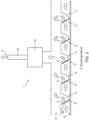
- Fig. 3 shows a third embodiment of the passive air purifying apparatus 1.
- the passive air purifying apparatus 1 comprises air guiding panels 11 placed along the air duct 4 that guides the pressure difference generated by passing vehicles V towards and through the inlets 2.
- the inlets comprise a grid 23 that shields an interior of the air duct from solid particles, in particular solid particles sized in the range 1 - 50 mm. This way, entrance of e.g. pieces of asphalt or other solid particles that might damage the (interior of) the inlet 2 and/or the air duct 4 may be counteracted.
- the passive air purifying apparatus 1 further comprises an air purifying filter 12 that is arranged in the air duct 4.
- the outlet 3 corresponds to the outlet of the flue 9. As shown, the roadside air is filtered before it is expelled from the outlet 3.
- a plurality of interspaced inlets 3 are placed longitudinally along the air duct 4.
- the interspace between successive inlets 3 of the plurality of interspaced inlets 3 may e.g. be between 0.1 - 10 m, such as between 0.5 - 9 m, 1 - 8 m, or 2 - 5 m.
- Each inlet 3 is provided with a one-way valve 5 that is biased towards the closed position.
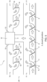
- Fig. 4 shows a fourth embodiment of the passive air purifying apparatus 1.
- the passive air purifying apparatus 1 comprises a second inlet 13, a second outlet 14 and a second air duct 15 connecting the second inlet 13 with the second outlet 14.
- the second outlet 14 is positioned along the roadside R.
- the second inlet 13 is positioned remote from the roadside R.
- the second outlet 14 is provided with an opposite one-way valve 16 that is also biased towards a closed position I.
- the bias is such that the opposite one-way valve 16 opens when an absolute value of the second valve pressure difference between a side of the opposite one-way valve 16 that faces away from the second air duct 15 and a side of the opposite one-way valve 16 that faces towards the second air duct 15 exceeds a second threshold value.
- the second threshold value is chosen such that an under-pressure generated at a trailing end and/or side of a passing vehicle V leads to a second valve pressure difference that is greater than the second threshold value.
- the second threshold value may be proportional to or a multiple of the first threshold value.
- the opposite one-way valve 16 comprises a second flap 17 for actuating the opposite one-way valve 16 from a closed I to an open position II.
- the second flap 17 forms a second valve body 18 which second valve body 18 engages a second valve seat 19 when being in the closed position I.
- the second flap 17 is configured for actuating the second valve body 18 to bring it from the closed I to the open position II.
- Fig. 5 shows a fifth embodiment of the passive air purifying apparatus 1 comprising the air purifying filter 12.
- the air purifying filter 12 forms a passage that fluidly couples the air duct 4 to the second air duct 15, thereby forming an air duct unit 24.
- Fig. 6 shows a road tunnel 20 provided with the passive air purifying apparatus 1.
- the depicted road tunnel 20 is a two-way tunnel.
- Passive air purifying apparatuses 1 are provided inside the tunnel 20, in particular along the side and upper-part of the tunnel 20.
- Each inlet 3 is provided with a one-way valve 5 that is biased towards the closed position I.
- the vehicle V on the left side of the tunnel 20 causes the one-way valves 5 on the left-hand side to move to the open position II whilst the one-way valves 5 on the right-hand side remain substantially closed.
- the passive air purifying apparatus 1 comprises at least one ventilator 21 for actively generating an above-ambient pressure inside the air duct to e.g. provide a safe passage there through with clean air and good visibility allowing people to use air duct 4 as an escape route 22 in case of fire.
- the air duct 4 is dimensioned such that humans may use it as escape route 22.
- the passive air purifying apparatus may comprise alternating sections of air ducts and second air ducts.
- inlets and second outlets may be conveniently disposed along the roadside to disperse roadside air whilst inducing an inflow of ambient air.
- the over-pressure generated at a front face/leading edge and the under-pressure generated at the trailing end and/or side of passing vehicles may beneficially be utilized substantially simultaneously.
- the road tunnel may additionally or alternatively be provided with second outlets associated with second air ducts for contributing to an inflow of ambient air to dilute the roadside air.
- inlets and/or outlets of the air purifying apparatus may be provided with a plurality of one-way valves.
- the passive air purifying apparatus may comprise at least one ventilator for actively removing smoke from the tunnel in case of fire.
- the air duct may be at least partially submerged and/or accommodated within the ground.
- facades in/of buildings, in particular buildings along the roadside may be provided with the passive air purifying apparatus without extending beyond the scope of the invention.
- additional one-way valves may be placed in the air duct to counteract backflow of air within the duct.
- the at least one outlet may be integrated in e.g. lampposts, electricity poles and/or (tele)communication masts.
- an energy generation device may be placed in the air duct for generating energy from the over-pressure generated from passing vehicles.
- the at least one air guiding panel and/or air scoop may extend from the inlet to direct the over-pressure generated by a passing vehicle towards the one-way valve.
- each air guiding panel may have a cross section formed as an airfoil and/or a double curved airfoil. Said over-pressure may then be urged towards the one-way valve.
- the at least one air guiding panel and/or air scoop may be placed substantially parallel to the inlet to guide the airflow generated by passing vehicles toward and/or through the at least one inlet. This way, a momentum of airflow may be led towards and generate a pressure difference at the one-way valve in the inlet.
- a span of the airfoil shaped air guiding panel may extend along the longitudinal direction of the air duct.
- a plurality of interspaced airfoil shaped air guiding panels may be placed longitudinally along the air duct, in particular such that each guiding panel corresponds to a respective inlet of the plurality of interspaced inlets that are placed longitudinally along the air duct.
- the span of the airfoil shaped air guiding panel may extend substantially transverse to the longitudinal direction of the air duct, in particular along a width direction of the air duct. This may be done in addition to or as an alternative to the longitudinally extending air guiding panels.
- the transversely extending air guiding panel may e.g.
- a free end of the air guiding panel or so-called wingtip of the airfoil shaped air guiding panel may e.g. be provided with a wingtip device or winglet. This way, wingtip vortices may be reduced and/or controllability of the airflow may be improved. This can facilitate feeding of roadside air into the air duct through the at least one inlet using the over-pressure generated by a passing vehicle .
Landscapes
- Engineering & Computer Science (AREA)
- Mining & Mineral Resources (AREA)
- Geology (AREA)
- Life Sciences & Earth Sciences (AREA)
- Structural Engineering (AREA)
- Civil Engineering (AREA)
- Architecture (AREA)
- General Life Sciences & Earth Sciences (AREA)
- Geochemistry & Mineralogy (AREA)
- Mechanical Engineering (AREA)
- Physics & Mathematics (AREA)
- Environmental & Geological Engineering (AREA)
- Fluid Mechanics (AREA)
- Road Paving Structures (AREA)
- Filtering Of Dispersed Particles In Gases (AREA)
Claims (14)
- Appareil de purification d'air passif (1) pour le bord de route (R), comprenant au moins une première entrée (2), et au moins une première sortie (3) et un conduit d'air (4) reliant la ou les premières entrées (2) à la ou aux premières sorties (3), la ou les premières entrées (2) étant positionnées le long du bord de route (R), la ou les premières sorties (3) étant positionnées à distance du bord de route (R), la première entrée (2) étant pourvue d'une valve unidirectionnelle (5) qui est sollicitée vers une position fermée (I), la sollicitation étant telle que la valve unidirectionnelle (5) s'ouvre lorsqu'une différence de pression de valve entre un côté de la valve unidirectionnelle (5) qui est opposé au conduit d'air (4) et un côté de la valve unidirectionnelle (5) qui est tourné vers le conduit d'air (4) dépasse une valeur seuil, la valeur seuil étant choisie de telle sorte qu'une surpression générée par un véhicule passant (V) conduise à une différence de pression de valve qui est supérieure à la valeur seuil, caractérisé en ce que ledit appareil de purification d'air passif comprenant en outre au moins une seconde entrée, au moins une seconde sortie et un second conduit d'air (15) reliant la ou les secondes entrées à la ou les secondes sorties, la ou les secondes sorties étant positionnées le long du bord de la route (R) et la ou les secondes entrées étant positionnées à distance du bord de la route (R), la ou les secondes sorties étant pourvues d'une valve unidirectionnelle opposée (16) qui est également sollicitée vers une position fermée (I), la sollicitation étant telle que la valve unidirectionnelle opposée (16) s'ouvre lorsqu'une seconde différence de pression de valve entre un côté de la valve unidirectionnelle opposée (16) qui est opposé au second conduit d'air (15) et un côté de la valve unidirectionnelle opposée (16) qui est tourné vers le second conduit d'air (15) dépasse une seconde valeur seuil, la seconde valeur seuil étant choisie de telle sorte qu'une sous-pression générée par un véhicule passant (V) conduise à une seconde différence de pression de valve qui est supérieure à la seconde valeur seuil.
- Appareil de purification d'air passif (1) selon la revendication 1,dans lequel la valve unidirectionnelle (5) comprend un volet pour actionner la valve unidirectionnelle (5) de la position fermée à une position ouverte (II),de préférence dans lequel le volet est relié à et/ou fait partie d'un corps de valve (7) lequel corps de valve s'engage dans un siège de valve (8) lorsque la valve unidirectionnelle (5) est dans la position fermée (I), et ledit volet étant configuré pour actionner le corps de valve (7) pour l'amener de la position fermée à une position ouverte (II).
- Appareil de purification d'air passif (1) selon l'une quelconque des revendications précédentes, dans lequel la ou les premières sorties (3) comprennent un conduit de fumée (9).
- Appareil de purification d'air passif (1) selon l'une quelconque des revendications précédentes,dans lequel la ou les premières sorties (3), en particulier une sortie du conduit de fumée (9) selon la revendication 3, sont placées à distance d'un bord de route (R), de préférence à une position élevée transversalement à un plan du bord de route (R) ; et/oudans lequel la ou les premières sorties (3), en particulier comprenant le conduit de fumée (9) selon la revendication 3, sont configurées pour générer passivement une sous-pression dans le conduit d'air (4), comme par exemple en comprenant un capuchon, un capot et/ou un ventilateur à turbine (10) ; et/oudans lequel une pluralité de premières sorties successives (3), en particulier des conduits de fumée (9) selon la revendication 3, sont placées à intervalles le long du conduit d'air (4).
- Appareil de purification d'air passif (1) selon l'une quelconque des revendications précédentes, dans lequel une pluralité de premières entrées (2) espacées sont placées le long du conduit d'air (4), par exemple longitudinalement ou transversalement, et dans lequel sensiblement chaque première entrée (2) est pourvue d'une valve unidirectionnelle (5) qui est sollicitée vers la position fermée (I).
- Appareil de purification d'air passif (1) selon l'une quelconque des revendications précédentes,dans lequel l'appareil de purification d'air passif (1) comprend au moins un panneau de guidage d'air (11) placé le long du conduit d'air (4) qui guide le flux d'air généré par le passage de véhicules (V) vers et/ou à travers la ou les premières entrées (2) ; et/oudans lequel la ou les premières entrées (2) comprennent une grille (23) qui protège l'intérieur du conduit d'air (4) des particules solides, en particulier des particules solides de taille comprise entre 1 et 50 mm ; et/oudans lequel le conduit d'air (4) est divisé en une pluralité de sections sur sa longueur.
- Appareil de purification d'air passif (1) selon l'une quelconque des revendications précédentes,dans lequel la valve unidirectionnelle opposée (16) comprend un second volet (17) pour actionner la valve unidirectionnelle opposée (16) de la position fermée (I) à une position ouverte (II),de préférence dans lequel le second volet (17) est relié à et/ou fait partie d'un second corps de valve (18), lequel second corps de valve (18) vient en prise avec un second siège de valve (19) lorsque la valve unidirectionnelle opposée (16) est dans la position fermée (I), et le second volet (17) est configuré pour actionner le second corps de valve (18) pour l'amener de la position fermée (I) à une position ouverte (II).
- Appareil de purification d'air passif (1) selon l'une quelconque des revendications précédentes, comprenant en outre un filtre de purification d'air (12) qui est disposé dans le conduit d'air (4), de préférence dans lequel le filtre de purification d'air (12) forme un passage qui relie de manière fluidique le conduit d'air (4) au second conduit d'air (15) selon la revendication 7, formant ainsi une unité de conduit d'air (24).
- Appareil de purification d'air passif (1) selon l'une quelconque des revendications précédentes, dans lequel la valve unidirectionnelle (5) comprend une pluralité de segments de valve, chaque segment de valve étant sollicité vers la position fermée (I).
- Tunnel routier (20) pourvu d'un appareil de purification d'air passif (1) selon l'une quelconque des revendications précédentes.
- Tunnel routier (20) selon la revendication 10, dans lequel le conduit d'air (4) est dimensionné pour accueillir au moins un humain, et dans lequel ledit conduit d'air (4) est pourvu d'au moins une entrée accessible depuis le bord de la route (R).
- Tunnel routier selon la revendication 11, dans lequel le dispositif de purification d'air (1) comprend un dispositif de ventilation à surpression (21) pour générer activement une pression supérieure à la pression ambiante à l'intérieur du conduit d'air (4).
- Procédé de purification passive de l'air le long d'un bord de route (R), le procédé comprenant les étapes consistant à :- fournir un appareil de purification d'air passif (1) selon l'une quelconque des revendications 1 à 9 :- utiliser une différence de pression générée par le passage de véhicules (V) pour ouvrir une valve unidirectionnelle d'une première entrée (2) vers un conduit d'air (4), la valve unidirectionnelle (5) étant sollicitée vers une position fermée (I) ;- aspirer de l'air dans le conduit d'air (4) par la première entrée (2) en générant passivement une sous-pression dans le conduit d'air (4) avec une première sortie (3) du conduit d'air (4) ; et- évacuer l'air le long d'un bord de route (R) et le disperser dans l'atmosphère par la première sortie (3).
- Procédé selon la revendication 13, comprenant en outre l'étape consistant à :
purifier l'air à l'intérieur du conduit d'air (4) avec un filtre purificateur d'air (12) placé dans le conduit d'air (4).
Applications Claiming Priority (2)
| Application Number | Priority Date | Filing Date | Title |
|---|---|---|---|
| NL2022717A NL2022717B1 (en) | 2019-03-11 | 2019-03-11 | Air purifying apparatus, road tunnel comprising said air purifying apparatus and method for purifying air |
| PCT/NL2020/050157 WO2020185078A1 (fr) | 2019-03-11 | 2020-03-11 | Appareil de purification d'air, tunnel routier comprenant ledit appareil de purification d'air et procédé de purification d'air |
Publications (3)
| Publication Number | Publication Date |
|---|---|
| EP3938579A1 EP3938579A1 (fr) | 2022-01-19 |
| EP3938579C0 EP3938579C0 (fr) | 2025-01-15 |
| EP3938579B1 true EP3938579B1 (fr) | 2025-01-15 |
Family
ID=66380086
Family Applications (1)
| Application Number | Title | Priority Date | Filing Date |
|---|---|---|---|
| EP20712706.9A Active EP3938579B1 (fr) | 2019-03-11 | 2020-03-11 | Appareil de purification d'air, tunnel routier comprenant ledit appareil de purification d'air et procédé de purification d'air |
Country Status (3)
| Country | Link |
|---|---|
| EP (1) | EP3938579B1 (fr) |
| NL (1) | NL2022717B1 (fr) |
| WO (1) | WO2020185078A1 (fr) |
Families Citing this family (1)
| Publication number | Priority date | Publication date | Assignee | Title |
|---|---|---|---|---|
| CN117344678A (zh) * | 2023-11-13 | 2024-01-05 | 兰州理工大学 | 高速公路雾区引导装置 |
Family Cites Families (4)
| Publication number | Priority date | Publication date | Assignee | Title |
|---|---|---|---|---|
| ATE538253T1 (de) * | 2004-09-06 | 2012-01-15 | Charlotte Make | Lärmschutzwand mit filter |
| JP2008307468A (ja) * | 2007-06-14 | 2008-12-25 | Panasonic Corp | 空気浄化装置 |
| NL1034614C2 (nl) * | 2007-11-01 | 2009-05-06 | Blue Temple B V | Geluidsscherm, schermelement en vangrails. |
| NL2001650C2 (nl) * | 2008-06-05 | 2009-12-08 | Blue Temple B V | Filterinrichting en filter voor toepassing daarin alsmede een afscheidingsscherm voor plaatsing langs een verkeersweg. |
-
2019
- 2019-03-11 NL NL2022717A patent/NL2022717B1/en active
-
2020
- 2020-03-11 WO PCT/NL2020/050157 patent/WO2020185078A1/fr not_active Ceased
- 2020-03-11 EP EP20712706.9A patent/EP3938579B1/fr active Active
Also Published As
| Publication number | Publication date |
|---|---|
| WO2020185078A1 (fr) | 2020-09-17 |
| EP3938579A1 (fr) | 2022-01-19 |
| EP3938579C0 (fr) | 2025-01-15 |
| NL2022717B1 (en) | 2020-09-18 |
Similar Documents
| Publication | Publication Date | Title |
|---|---|---|
| CN100557191C (zh) | 隧道排烟方法及带独立排烟装置的隧道通风系统 | |
| KR100886350B1 (ko) | 인공지능형 선택 급배기 방식의 터널 환기시스템 | |
| KR101244372B1 (ko) | 자동 개폐 댐퍼를 이용한 종류식 환기 및 횡류식 제연 병용장치 및 그 장치의 운용방법 | |
| CN101275468A (zh) | 城市隧道竖井型自然通风与防排烟方法 | |
| KR101239365B1 (ko) | 상호 보완적 터널환기장치 및 이를 이용한 터널환기방법 | |
| CN102400701A (zh) | 公路隧道互通式纵向通风方式 | |
| EP3938579B1 (fr) | Appareil de purification d'air, tunnel routier comprenant ledit appareil de purification d'air et procédé de purification d'air | |
| KR101710459B1 (ko) | 도심지 횡류 또는 반횡류 터널의 배연성능 향상을 위한 급기 및 배기장치 | |
| CN102050121B (zh) | 超音速免维护冲压式真空管道运输系统 | |
| US20030091394A1 (en) | Covered highway structure with means for easy and quick access to tunnel interior | |
| CN111764948B (zh) | 公路隧道群防灾系统 | |
| ITPD20090011A1 (it) | Dispositivo per l'aspirazione e filtrazione di polveri sottili nell'aria | |
| KR101233442B1 (ko) | 정압 보상형 지하주차장 환기장치 | |
| CN206889008U (zh) | 一种用于非全封闭站台门系统地铁车站的喷嘴送风系统 | |
| CN208534524U (zh) | 一种用于隧道的高效通风系统 | |
| KR101732405B1 (ko) | 열차풍을 이용한 승강장 배기장치 | |
| KR20140025805A (ko) | 도시철도 본선터널의 수직환기구 풍도 내 가이드 베인 설치를 통한 압력 강하방지 및 유지 구조 | |
| KR100529046B1 (ko) | 지하철 에어커튼장치 및 이를 이용한 에어커튼 형성방법 | |
| CN119102719A (zh) | 一种应用于隧道侧排的可移动式通风兼排烟系统 | |
| KR20140093202A (ko) | 도시철도 본선터널의 수직환기구 입구 유동 병목현상 제거 구조 | |
| CN210714755U (zh) | 城市多功能隧道的通风系统 | |
| KR20090082950A (ko) | 개량된 제트팬 | |
| KR102243704B1 (ko) | 터널 사이드에 복수설치가 가능한 임펠러 없는 환기팬 | |
| JP2000120399A (ja) | 長大トンネルの換気システム | |
| CN111365055B (zh) | 一种螺旋隧道用引射式通风排烟系统 |
Legal Events
| Date | Code | Title | Description |
|---|---|---|---|
| STAA | Information on the status of an ep patent application or granted ep patent |
Free format text: STATUS: UNKNOWN |
|
| STAA | Information on the status of an ep patent application or granted ep patent |
Free format text: STATUS: THE INTERNATIONAL PUBLICATION HAS BEEN MADE |
|
| PUAI | Public reference made under article 153(3) epc to a published international application that has entered the european phase |
Free format text: ORIGINAL CODE: 0009012 |
|
| STAA | Information on the status of an ep patent application or granted ep patent |
Free format text: STATUS: REQUEST FOR EXAMINATION WAS MADE |
|
| 17P | Request for examination filed |
Effective date: 20211005 |
|
| AK | Designated contracting states |
Kind code of ref document: A1 Designated state(s): AL AT BE BG CH CY CZ DE DK EE ES FI FR GB GR HR HU IE IS IT LI LT LU LV MC MK MT NL NO PL PT RO RS SE SI SK SM TR |
|
| DAV | Request for validation of the european patent (deleted) | ||
| DAX | Request for extension of the european patent (deleted) | ||
| STAA | Information on the status of an ep patent application or granted ep patent |
Free format text: STATUS: EXAMINATION IS IN PROGRESS |
|
| 17Q | First examination report despatched |
Effective date: 20231011 |
|
| GRAP | Despatch of communication of intention to grant a patent |
Free format text: ORIGINAL CODE: EPIDOSNIGR1 |
|
| STAA | Information on the status of an ep patent application or granted ep patent |
Free format text: STATUS: GRANT OF PATENT IS INTENDED |
|
| RIC1 | Information provided on ipc code assigned before grant |
Ipc: E21F 1/00 20060101ALI20240718BHEP Ipc: E21B 1/00 20060101ALI20240718BHEP Ipc: E01F 15/04 20060101ALI20240718BHEP Ipc: E01C 1/00 20060101AFI20240718BHEP |
|
| INTG | Intention to grant announced |
Effective date: 20240806 |
|
| GRAS | Grant fee paid |
Free format text: ORIGINAL CODE: EPIDOSNIGR3 |
|
| GRAA | (expected) grant |
Free format text: ORIGINAL CODE: 0009210 |
|
| STAA | Information on the status of an ep patent application or granted ep patent |
Free format text: STATUS: THE PATENT HAS BEEN GRANTED |
|
| AK | Designated contracting states |
Kind code of ref document: B1 Designated state(s): AL AT BE BG CH CY CZ DE DK EE ES FI FR GB GR HR HU IE IS IT LI LT LU LV MC MK MT NL NO PL PT RO RS SE SI SK SM TR |
|
| REG | Reference to a national code |
Ref country code: CH Ref legal event code: EP Ref country code: GB Ref legal event code: FG4D |
|
| REG | Reference to a national code |
Ref country code: DE Ref legal event code: R096 Ref document number: 602020044768 Country of ref document: DE |
|
| REG | Reference to a national code |
Ref country code: IE Ref legal event code: FG4D |
|
| U01 | Request for unitary effect filed |
Effective date: 20250212 |
|
| U07 | Unitary effect registered |
Designated state(s): AT BE BG DE DK EE FI FR IT LT LU LV MT NL PT RO SE SI Effective date: 20250218 |
|
| U20 | Renewal fee for the european patent with unitary effect paid |
Year of fee payment: 6 Effective date: 20250218 |
|
| PG25 | Lapsed in a contracting state [announced via postgrant information from national office to epo] |
Ref country code: RS Free format text: LAPSE BECAUSE OF FAILURE TO SUBMIT A TRANSLATION OF THE DESCRIPTION OR TO PAY THE FEE WITHIN THE PRESCRIBED TIME-LIMIT Effective date: 20250415 |
|
| PG25 | Lapsed in a contracting state [announced via postgrant information from national office to epo] |
Ref country code: PL Free format text: LAPSE BECAUSE OF FAILURE TO SUBMIT A TRANSLATION OF THE DESCRIPTION OR TO PAY THE FEE WITHIN THE PRESCRIBED TIME-LIMIT Effective date: 20250115 |
|
| PG25 | Lapsed in a contracting state [announced via postgrant information from national office to epo] |
Ref country code: ES Free format text: LAPSE BECAUSE OF FAILURE TO SUBMIT A TRANSLATION OF THE DESCRIPTION OR TO PAY THE FEE WITHIN THE PRESCRIBED TIME-LIMIT Effective date: 20250115 |
|
| PG25 | Lapsed in a contracting state [announced via postgrant information from national office to epo] |
Ref country code: IS Free format text: LAPSE BECAUSE OF FAILURE TO SUBMIT A TRANSLATION OF THE DESCRIPTION OR TO PAY THE FEE WITHIN THE PRESCRIBED TIME-LIMIT Effective date: 20250515 Ref country code: NO Free format text: LAPSE BECAUSE OF FAILURE TO SUBMIT A TRANSLATION OF THE DESCRIPTION OR TO PAY THE FEE WITHIN THE PRESCRIBED TIME-LIMIT Effective date: 20250415 |
|
| PG25 | Lapsed in a contracting state [announced via postgrant information from national office to epo] |
Ref country code: HR Free format text: LAPSE BECAUSE OF FAILURE TO SUBMIT A TRANSLATION OF THE DESCRIPTION OR TO PAY THE FEE WITHIN THE PRESCRIBED TIME-LIMIT Effective date: 20250115 |
|
| PG25 | Lapsed in a contracting state [announced via postgrant information from national office to epo] |
Ref country code: GR Free format text: LAPSE BECAUSE OF FAILURE TO SUBMIT A TRANSLATION OF THE DESCRIPTION OR TO PAY THE FEE WITHIN THE PRESCRIBED TIME-LIMIT Effective date: 20250416 |
|
| PGFP | Annual fee paid to national office [announced via postgrant information from national office to epo] |
Ref country code: CH Payment date: 20250401 Year of fee payment: 6 |
|
| PG25 | Lapsed in a contracting state [announced via postgrant information from national office to epo] |
Ref country code: SM Free format text: LAPSE BECAUSE OF FAILURE TO SUBMIT A TRANSLATION OF THE DESCRIPTION OR TO PAY THE FEE WITHIN THE PRESCRIBED TIME-LIMIT Effective date: 20250115 |
|
| PG25 | Lapsed in a contracting state [announced via postgrant information from national office to epo] |
Ref country code: MC Free format text: LAPSE BECAUSE OF FAILURE TO SUBMIT A TRANSLATION OF THE DESCRIPTION OR TO PAY THE FEE WITHIN THE PRESCRIBED TIME-LIMIT Effective date: 20250115 |
|
| PG25 | Lapsed in a contracting state [announced via postgrant information from national office to epo] |
Ref country code: CZ Free format text: LAPSE BECAUSE OF FAILURE TO SUBMIT A TRANSLATION OF THE DESCRIPTION OR TO PAY THE FEE WITHIN THE PRESCRIBED TIME-LIMIT Effective date: 20250115 |
|
| PG25 | Lapsed in a contracting state [announced via postgrant information from national office to epo] |
Ref country code: SK Free format text: LAPSE BECAUSE OF FAILURE TO SUBMIT A TRANSLATION OF THE DESCRIPTION OR TO PAY THE FEE WITHIN THE PRESCRIBED TIME-LIMIT Effective date: 20250115 |
|
| PLBE | No opposition filed within time limit |
Free format text: ORIGINAL CODE: 0009261 |
|
| STAA | Information on the status of an ep patent application or granted ep patent |
Free format text: STATUS: NO OPPOSITION FILED WITHIN TIME LIMIT |
|
| REG | Reference to a national code |
Ref country code: CH Ref legal event code: L10 Free format text: ST27 STATUS EVENT CODE: U-0-0-L10-L00 (AS PROVIDED BY THE NATIONAL OFFICE) Effective date: 20251126 |
|
| 26N | No opposition filed |
Effective date: 20251016 |
|
| PG25 | Lapsed in a contracting state [announced via postgrant information from national office to epo] |
Ref country code: IE Free format text: LAPSE BECAUSE OF NON-PAYMENT OF DUE FEES Effective date: 20250311 |
|
| REG | Reference to a national code |
Ref country code: CH Ref legal event code: U11 Free format text: ST27 STATUS EVENT CODE: U-0-0-U10-U11 (AS PROVIDED BY THE NATIONAL OFFICE) Effective date: 20260401 |
|
| PGFP | Annual fee paid to national office [announced via postgrant information from national office to epo] |
Ref country code: GB Payment date: 20260324 Year of fee payment: 7 |
|
| U20 | Renewal fee for the european patent with unitary effect paid |
Year of fee payment: 7 Effective date: 20260326 |