EP3938662B1 - Dispositif de fixation anti-vibration à pièces multiples - Google Patents
Dispositif de fixation anti-vibration à pièces multiples Download PDFInfo
- Publication number
- EP3938662B1 EP3938662B1 EP20771040.1A EP20771040A EP3938662B1 EP 3938662 B1 EP3938662 B1 EP 3938662B1 EP 20771040 A EP20771040 A EP 20771040A EP 3938662 B1 EP3938662 B1 EP 3938662B1
- Authority
- EP
- European Patent Office
- Prior art keywords
- fastener
- intermediate component
- enlarged
- screw
- head
- Prior art date
- Legal status (The legal status is an assumption and is not a legal conclusion. Google has not performed a legal analysis and makes no representation as to the accuracy of the status listed.)
- Active
Links
Images





Classifications
-
- F—MECHANICAL ENGINEERING; LIGHTING; HEATING; WEAPONS; BLASTING
- F16—ENGINEERING ELEMENTS AND UNITS; GENERAL MEASURES FOR PRODUCING AND MAINTAINING EFFECTIVE FUNCTIONING OF MACHINES OR INSTALLATIONS; THERMAL INSULATION IN GENERAL
- F16B—DEVICES FOR FASTENING OR SECURING CONSTRUCTIONAL ELEMENTS OR MACHINE PARTS TOGETHER, e.g. NAILS, BOLTS, CIRCLIPS, CLAMPS, CLIPS OR WEDGES; JOINTS OR JOINTING
- F16B2/00—Friction-grip releasable fastenings
- F16B2/02—Clamps, i.e. with gripping action effected by positive means other than the inherent resistance to deformation of the material of the fastening
- F16B2/06—Clamps, i.e. with gripping action effected by positive means other than the inherent resistance to deformation of the material of the fastening external, i.e. with contracting action
- F16B2/065—Clamps, i.e. with gripping action effected by positive means other than the inherent resistance to deformation of the material of the fastening external, i.e. with contracting action using screw-thread elements
-
- F—MECHANICAL ENGINEERING; LIGHTING; HEATING; WEAPONS; BLASTING
- F16—ENGINEERING ELEMENTS AND UNITS; GENERAL MEASURES FOR PRODUCING AND MAINTAINING EFFECTIVE FUNCTIONING OF MACHINES OR INSTALLATIONS; THERMAL INSULATION IN GENERAL
- F16B—DEVICES FOR FASTENING OR SECURING CONSTRUCTIONAL ELEMENTS OR MACHINE PARTS TOGETHER, e.g. NAILS, BOLTS, CIRCLIPS, CLAMPS, CLIPS OR WEDGES; JOINTS OR JOINTING
- F16B39/00—Locking of screws, bolts or nuts
- F16B39/02—Locking of screws, bolts or nuts in which the locking takes place after screwing down
- F16B39/028—Locking of screws, bolts or nuts in which the locking takes place after screwing down by means of an auxiliary bolt or threaded element whose action provokes the deformation of the main bolt or nut and thereby its blocking
-
- F—MECHANICAL ENGINEERING; LIGHTING; HEATING; WEAPONS; BLASTING
- F16—ENGINEERING ELEMENTS AND UNITS; GENERAL MEASURES FOR PRODUCING AND MAINTAINING EFFECTIVE FUNCTIONING OF MACHINES OR INSTALLATIONS; THERMAL INSULATION IN GENERAL
- F16B—DEVICES FOR FASTENING OR SECURING CONSTRUCTIONAL ELEMENTS OR MACHINE PARTS TOGETHER, e.g. NAILS, BOLTS, CIRCLIPS, CLAMPS, CLIPS OR WEDGES; JOINTS OR JOINTING
- F16B37/00—Nuts or like thread-engaging members
- F16B37/12—Nuts or like thread-engaging members with thread-engaging surfaces formed by inserted coil-springs, discs, or the like; Independent pieces of wound wire used as nuts; Threaded inserts for holes
- F16B37/122—Threaded inserts, e.g. "rampa bolts"
- F16B37/125—Threaded inserts, e.g. "rampa bolts" the external surface of the insert being threaded
-
- F—MECHANICAL ENGINEERING; LIGHTING; HEATING; WEAPONS; BLASTING
- F16—ENGINEERING ELEMENTS AND UNITS; GENERAL MEASURES FOR PRODUCING AND MAINTAINING EFFECTIVE FUNCTIONING OF MACHINES OR INSTALLATIONS; THERMAL INSULATION IN GENERAL
- F16B—DEVICES FOR FASTENING OR SECURING CONSTRUCTIONAL ELEMENTS OR MACHINE PARTS TOGETHER, e.g. NAILS, BOLTS, CIRCLIPS, CLAMPS, CLIPS OR WEDGES; JOINTS OR JOINTING
- F16B39/00—Locking of screws, bolts or nuts
- F16B39/02—Locking of screws, bolts or nuts in which the locking takes place after screwing down
-
- F—MECHANICAL ENGINEERING; LIGHTING; HEATING; WEAPONS; BLASTING
- F16—ENGINEERING ELEMENTS AND UNITS; GENERAL MEASURES FOR PRODUCING AND MAINTAINING EFFECTIVE FUNCTIONING OF MACHINES OR INSTALLATIONS; THERMAL INSULATION IN GENERAL
- F16B—DEVICES FOR FASTENING OR SECURING CONSTRUCTIONAL ELEMENTS OR MACHINE PARTS TOGETHER, e.g. NAILS, BOLTS, CIRCLIPS, CLAMPS, CLIPS OR WEDGES; JOINTS OR JOINTING
- F16B39/00—Locking of screws, bolts or nuts
- F16B39/22—Locking of screws, bolts or nuts in which the locking takes place during screwing down or tightening
-
- F—MECHANICAL ENGINEERING; LIGHTING; HEATING; WEAPONS; BLASTING
- F16—ENGINEERING ELEMENTS AND UNITS; GENERAL MEASURES FOR PRODUCING AND MAINTAINING EFFECTIVE FUNCTIONING OF MACHINES OR INSTALLATIONS; THERMAL INSULATION IN GENERAL
- F16B—DEVICES FOR FASTENING OR SECURING CONSTRUCTIONAL ELEMENTS OR MACHINE PARTS TOGETHER, e.g. NAILS, BOLTS, CIRCLIPS, CLAMPS, CLIPS OR WEDGES; JOINTS OR JOINTING
- F16B41/00—Measures against loss of bolts, nuts, or pins; Measures against unauthorised operation of bolts, nuts or pins
- F16B41/002—Measures against loss of bolts, nuts or pins
-
- F—MECHANICAL ENGINEERING; LIGHTING; HEATING; WEAPONS; BLASTING
- F16—ENGINEERING ELEMENTS AND UNITS; GENERAL MEASURES FOR PRODUCING AND MAINTAINING EFFECTIVE FUNCTIONING OF MACHINES OR INSTALLATIONS; THERMAL INSULATION IN GENERAL
- F16B—DEVICES FOR FASTENING OR SECURING CONSTRUCTIONAL ELEMENTS OR MACHINE PARTS TOGETHER, e.g. NAILS, BOLTS, CIRCLIPS, CLAMPS, CLIPS OR WEDGES; JOINTS OR JOINTING
- F16B5/00—Joining sheets or plates, e.g. panels, to one another or to strips or bars parallel to them
- F16B5/02—Joining sheets or plates, e.g. panels, to one another or to strips or bars parallel to them by means of fastening members using screw-thread
-
- F—MECHANICAL ENGINEERING; LIGHTING; HEATING; WEAPONS; BLASTING
- F16—ENGINEERING ELEMENTS AND UNITS; GENERAL MEASURES FOR PRODUCING AND MAINTAINING EFFECTIVE FUNCTIONING OF MACHINES OR INSTALLATIONS; THERMAL INSULATION IN GENERAL
- F16B—DEVICES FOR FASTENING OR SECURING CONSTRUCTIONAL ELEMENTS OR MACHINE PARTS TOGETHER, e.g. NAILS, BOLTS, CIRCLIPS, CLAMPS, CLIPS OR WEDGES; JOINTS OR JOINTING
- F16B5/00—Joining sheets or plates, e.g. panels, to one another or to strips or bars parallel to them
- F16B5/02—Joining sheets or plates, e.g. panels, to one another or to strips or bars parallel to them by means of fastening members using screw-thread
- F16B5/0241—Joining sheets or plates, e.g. panels, to one another or to strips or bars parallel to them by means of fastening members using screw-thread with the possibility for the connection to absorb deformation, e.g. thermal or vibrational
-
- F—MECHANICAL ENGINEERING; LIGHTING; HEATING; WEAPONS; BLASTING
- F16—ENGINEERING ELEMENTS AND UNITS; GENERAL MEASURES FOR PRODUCING AND MAINTAINING EFFECTIVE FUNCTIONING OF MACHINES OR INSTALLATIONS; THERMAL INSULATION IN GENERAL
- F16B—DEVICES FOR FASTENING OR SECURING CONSTRUCTIONAL ELEMENTS OR MACHINE PARTS TOGETHER, e.g. NAILS, BOLTS, CIRCLIPS, CLAMPS, CLIPS OR WEDGES; JOINTS OR JOINTING
- F16B33/00—Features common to bolt and nut
- F16B33/02—Shape of thread; Special thread-forms
- F16B2033/025—Shape of thread; Special thread-forms with left-hand thread
-
- F—MECHANICAL ENGINEERING; LIGHTING; HEATING; WEAPONS; BLASTING
- F16—ENGINEERING ELEMENTS AND UNITS; GENERAL MEASURES FOR PRODUCING AND MAINTAINING EFFECTIVE FUNCTIONING OF MACHINES OR INSTALLATIONS; THERMAL INSULATION IN GENERAL
- F16B—DEVICES FOR FASTENING OR SECURING CONSTRUCTIONAL ELEMENTS OR MACHINE PARTS TOGETHER, e.g. NAILS, BOLTS, CIRCLIPS, CLAMPS, CLIPS OR WEDGES; JOINTS OR JOINTING
- F16B33/00—Features common to bolt and nut
- F16B33/006—Non-metallic fasteners using screw-thread
-
- F—MECHANICAL ENGINEERING; LIGHTING; HEATING; WEAPONS; BLASTING
- F16—ENGINEERING ELEMENTS AND UNITS; GENERAL MEASURES FOR PRODUCING AND MAINTAINING EFFECTIVE FUNCTIONING OF MACHINES OR INSTALLATIONS; THERMAL INSULATION IN GENERAL
- F16B—DEVICES FOR FASTENING OR SECURING CONSTRUCTIONAL ELEMENTS OR MACHINE PARTS TOGETHER, e.g. NAILS, BOLTS, CIRCLIPS, CLAMPS, CLIPS OR WEDGES; JOINTS OR JOINTING
- F16B5/00—Joining sheets or plates, e.g. panels, to one another or to strips or bars parallel to them
- F16B5/06—Joining sheets or plates, e.g. panels, to one another or to strips or bars parallel to them by means of clamps or clips
- F16B5/0607—Joining sheets or plates, e.g. panels, to one another or to strips or bars parallel to them by means of clamps or clips joining sheets or plates to each other
- F16B5/0621—Joining sheets or plates, e.g. panels, to one another or to strips or bars parallel to them by means of clamps or clips joining sheets or plates to each other in parallel relationship
- F16B5/0642—Joining sheets or plates, e.g. panels, to one another or to strips or bars parallel to them by means of clamps or clips joining sheets or plates to each other in parallel relationship the plates being arranged one on top of the other and in full close contact with each other
Definitions
- the present invention relates generally to locking fasteners. More specifically, the present invention discloses a three piece locking fastener including an intermediate component which is interiorly threaded and open at opposite ends for receiving and first and second opposing directed and threaded screws.
- the first screw is exteriorly threaded for engaging with the threads of the intermediate component.
- the first screw also includes a hollow shaft which, upon being installed within a first end of the intermediate component, subsequently receives in a counter-rotatatively threaded fashion the second threaded screw, with loosening of either the opposing and inter-seating end screws being prevented via their counter-threaded orientations.
- fasteners such as which are configured in an attempt to prevent loosening when employed in dynamic environments.
- a first and most basic example of this is the conventional threaded bolt fastener with attachable and interiorly threaded nut.
- a spring washer can either be integrated into the nut or separately provided.
- the locking threaded fastener of Ewing US 5,314,279 , which teaches a locking threaded fastener of the wedge-action type with threaded and threadless nut members with wedge elements therebetween for wedging the nut members apart when the threaded nut member is turned in the loosening direction.
- the threadless nut member has a flat inner surface for engaging the workpiece and the wedge elements have engaging surfaces with a coefficient of friction therebetween which is less than that between the flat inner surface and the workpiece surface.
- a third nut member in the form of a washer, is provided with a flat inner surface for engaging the workpiece.
- the wedge elements have engaging surfaces with a coefficient of friction less than that between the third nut member and the threadless nut member which, in turn, is less than that between the third nut member in the workpiece.
- U.S. 5,562,379 to Rausch et al. , teaches a vibration resistant fastener having a pin and a collar.
- the pin is threaded or peripherally grooved.
- the major diameter of the thread or groove is reduced to a diameter which is still larger than its minor diameter.
- a collar is threaded or swaged on to the pin and collar material is pressed into an open region that was formed by the reduction of the major diameter, to form a thread lock.
- JP 3137118 U describes a bolt with a nut portion for tightening a bolt.
- the nut and the bolt are threaded so as to always rotate in opposite directions.
- An elastic body is sandwiched between the nut and the bolt so as to transmit the rotational motion.
- JP 08-232932 A describes a structure for reducing loosening torque of a bolt by screwing a first auxiliary bolt until it is engaged with a locking stepped part.
- a bolt is screwed to a fitting body.
- a second auxiliary bolt is screwed so as to be abutted on the first auxiliary bolt.
- JP 07-004418 A describes a locking structure for an object, constituted so that the locking of the object can be made stable by the use of an uncoupling prevention bolt.
- JP 2009-204153 A describes a nut having opposite screw threads.
- EP 0634583 A describes means for locking a nut on a bolt, comprising an inwardly tapered axial hole in the threaded end of the bolt, two diametrical slits at right angles to each other in the threaded end of the bolt which slits extend only partway along the threaded zone of the bolt, and a tapered pin adapted to be driven into the hole to expand the slit portion of the threaded zone of the bolt.
- JP 2011 012693 A describes a screw for holding including the female bolt having a flange-like holding part, in which a lock bolt insertion hole is passed through, that is formed in its one end, and an inner screw formed in its inner periphery, the male bolt having a flange-like holding part formed in its one end, an outer screw screwed in the inner screw of the female bolt, that is formed in an outer periphery of a rod-like part, and an inner screw screwing oppositely relative to the outer screw formed in the outer periphery of the rod-like part, that is formed in the inner periphery, and a lock bolt having an outer screw screwed in the inner screw formed in the rod-like part of the male bolt.
- JP H02 46308 A describes a cylindrical body formed at a point of a first screw member, and screws are formed each on a peripheral face and on an inner circumference of the cylindrical body.
- a first screw member is inserted from the one side of a through hole formed in two pieces of plate materials, while a second screw member is inserted from the other side.
- a third screw member is inserted into the cylindrical body of the first screw member from a through hole of the second screw member, and a screw of the third screw member is engaged in screws of the screw members, respectively.
- the present invention discloses a three piece locking fastener according to claim 1 including an interiorly threaded intermediate component open at opposite ends.
- a first screw having a first exterior thread pattern rotationally inter-engages with the interior threads of the intermediate component when installed through a first selected one of the opposite ends, the first screw having a hollow shaft exhibiting a further plurality of interior threads opposite a direction of the first thread pattern.
- a second screw has a second exterior thread pattern opposite the first pattern and, upon being installed within the other selected one of the opposite ends, rotationally inter-engages the interior threads of the first screw, so that loosening of either of the first and second screws being prevented by their counter-threaded orientation.
- Additional features include each of the intermediate component and a selected one of the first and second screws having an enlarged head with a number of interconnected sides having a polygonal shape.
- the second screw further includes a curved and enlarged diameter head.
- the intermediate component further includes an end proximate undercut recess for receiving the enlarged head of the second fastener.
- a recessed ledge is configured within the undercut recess of the intermediate component for seating an underside of the enlarged head of the second fastener in an installed position.
- a polygonal inner perimeter is configured in the undercut recess for communicating an extending stem of the second fastener within the intermediate component and in engagement with the hollow threaded interior of the previously installed first fastener.
- intermediate component and the first and second fasteners each further including a rigid material not limited to a steel or heavy duty nylon construction.
- the first and second layers have aligning apertures through which a stem portion of the intermediate component extends, with the enlarged polygonal shaped heads established by the intermediate component and the selected one of the first and second screws compressing against opposite edge surfaces of the layers adjoining the apertures.
- the present invention discloses a three piece locking fastener for use such as in dynamic environments in which vibrations and other effects are in play.
- This can include without limitation such operating environments as skate blade fasteners for compressively attaching a first blade layer to a second layer, such as further including a support plate or the like formed with the bottom of the skate.
- Other applications include the three piece fastener being integrated into a wheel to hub attachment interface, such as for a vehicle.
- the fastener assembly includes, at a minimum, an intermediate component which is interiorly threaded and open at opposite ends for receiving and first and second threaded screws.
- the first screw is exteriorly threaded for engaging with the threads of the intermediate component.
- the first screw includes a hollow shaft which, upon being installed within a first end of the intermediate component, subsequently receives in a counter-rotatatively threaded fashion a second threaded screw, with loosening of the opposing end screws being prevented via their counter-threaded orientation.
- the three piece fastener includes intermediate component 12 and first (bottom) hollow screw 14 and second (top) solid screw 16.
- the intermediate component 12 and first 14 and second 16 fasteners can be constructed of any rigid material not limited to steel, carbon steel or any durable composite (e.g. nylon or polymer) material.
- the screws 14 and 16 are also commonly termed as “threaded bolts” however can include any other suitable configuration for inter-engaging with the intermediate component 12 in the manner described herein.
- Figure 3 is a partially exploded view of Fig. 1 and illustrating the lower or first hollowed screw 14 engaged within the lower open and interiorly threaded end of the intermediate component 12 prior to engagement of the upper or second solid screw 16.
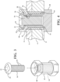
- Figure 4 is an axial cutaway view depicting the assembly of Fig. 1 and further showing first 2 and second 4 layers, each having aligning apertures depicted by inner perimeter surfaces 6 and 8, respectively, and through which a stem portion (again at 12) of the intermediate component extends.
- Figure 5 further provides is an exploded axial cutaway view corresponding to Fig. 2 of the three piece fastener.
- the layers 2 and 4 are generally represented and can include any configuration or application not limited in one potential application to such as an attachment fastener for a skate blade to a flange, bracket or other support surface.
- the layers 2 can correspond to an inner rim or wheel supporting a tire in attachment to a wheel hub.
- the present invention serves to provide a durable fastener arrangement which resists loosening in response to vibrations and the like, such as which can be typical of dynamic operating environments.
- the intermediate component includes an enlarged polygonal shaped head, such as which is depicted as a hex head configuration, see at 18, which is shown proximate its upper open end.
- At least one of the selected screws 14/16 (or bolt threads) likewise include an enlarged hex head which is depicted in Fig. 1 by hex head 20 associated with the lower or first bolt 14.
- the hex head can be substituted by any other circular or other type of fastening tool, such including but not limited to a multi-sided polygonal shape head having any of a triangular, square, pentagonal or other shape exhibiting a number of interconnected sides, it also being envisioned that the polygonal shaped enlarged heads can be reconfigured in other shapes consistent with the use of any tightening or loosening tool.
- the upper or second screw 16 includes a curved and enlarged diameter head 22.
- a tool bit engageable recess is formed in the enlarged head 22 to facilitate engagement by a tool bit (not shown) for securing the second (top) screw 16 following pre-threaded engagement of the exterior threads (at 24) of the lower screw 14 within the interior threads (at 26) of the intermediate component 12.
- the first screw 14 includes a hollow shaft (see generally at 28 in Fig. 2 ) exhibiting a further plurality of interior threads (further at 30) opposite a direction of the first thread pattern 24.
- the second screw 16 exhibits a second exterior thread pattern 32 opposite said first pattern and upon being installed within the other selected one of the opposite ends (depicted as the upper end of the intermediate component 12 in Figs. 1-5 ), results in rotationally inter-engaging of the thread pattern 32 with the matching interior thread pattern 30 of the first screw 14, with loosening of either of the first 14 and second 16 screws being prevented by their counter-threaded orientation.
- Additional features include the intermediate component 12 exhibiting an end proximate undercut recess, see annular inner rim surface 34 communicated with undercut ledge 36 in Fig. 2 , this for receiving and seating the enlarged head 22 of the second fastener 16 in the manner best further shown in Fig. 5 .
- a polygonal inner perimeter (see at 38) configured in the undercut recess for communicating the solid extending stem (at 40 in fig. 5 ) of the second fastener within the intermediate component 12 and into engagement with the hollow threaded interior 28 of the previously installed first fastener 14.
- the fasteners provided can again include, without limitation, any cross sectional shape not limited to circular or other configuration.
- Figure 6 is an assembled and partially transparent view of the three piece fastener as substantially shown in Fig. 1 , and further depicted at 10' with the direction of the first and second screw threads being reversed as referenced by threads 24' of the first fastener, at 14' as further shown in Fig. 7 , arranged in a reversed directional pattern from those depicted at 32' for second fastener 16', as also shown in Fig. 7.
- Figure 7 is an exploded view depicting the three piece fastener of Fig. 6 , similar to that previously shown in Fig. 2 and again with the intermediate component 12', first (bottom) hollow screw 14' and second (top solid screw) 16' with the reversed thread patterns 24' and 32'.
- An interior threaded pattern 30' of the intermediate component 12' (corresponding to that previously shown at 30 in Fig. 4 ) is likewise opposite that of the exterior threads 24'.
- the reference to screw thread direction can also include the terms first/second, left/right or first and second opposing interchangeably and without limitation.
- Figures 8-12 correspond to Figs. 1-5 in the presentation of a three piece fastener according to a second variant of the present disclosure.
- additional figure descriptions for each of second variant of Figs. 8-12 (and related sub-variant Figs. 13-14 ), as well as the third variant of Figs. 15-19 (and related sub-variant of Figs. 20-21 ) will be limited to pointing out differences from that previously illustrated and described in the first embodiment. Similar features will remain as previously described or illustrated.
- Figure 8 is an assembled and partially transparent view of the three piece fastener according to a second variant of the present disclosure.
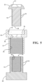
- Figure 9 is an exploded view depicting the three piece fastener of Fig. 8 and, in differentiation from that shown in Fig. 1 , exhibiting an alternately configured intermediate component 112 with a non-recessed upper end surface 114, this depicted in comparison to that shown in Fig. 1 , in combination with the first (bottom) hollow screw 14 and second (top) solid screw 16 as previously described and exhibiting the reversed thread directions.
- Figure 10 is a partially exploded view of Fig. 9 and illustrating the lower or first hollowed screw engaged within the lower open and interiorly threaded end of the intermediate component prior to engagement of the upper or second solid screw.
- Figure 11 is an axial cutaway view of the depicting the assembly of Fig. 8 and in which the domed or arcuate profile 22 of the upper second screw 16 projects above the upper surface ledge 14 of the intermediate component 112 (and as opposed to being recess seated within the recess profile depicted at the upper end of the intermediate component 12 of Fig. 1 with the underside of the enlarged screw head of the second screw supported upon the undercut ledge 32 in Fig. 1 ).
- Figure 12 is an exploded axial cutaway view corresponding to Fig. 9 , with Fig. 13 depicting is an assembled and partially transparent view of a three-piece fastener as substantially shown in Fig. 8 with the direction of the first and second screw threads being reversed.
- a square perimeter opening 38' is referenced in the intermediate component 112 which corresponds to that shown at 38 in Figs. 2 and 5 , however is relocated more proximate the upper surface 114 of the intermediate component 112.
- the dimensions of the reduced dimension square profile enable inserting passage there-through of the threaded stem or shaft 40 of the upper screw 16 (see also again Fig. 11 ).
- Figure 14 is an exploded view depicting the three piece fastener of Fig. 9 , again with the intermediate component 112 and first (bottom) hollow screw and second (top solid screw) and reverse thread patterns (see also Figs. 6-7 ) exhibited on the top and bottom screws and in the same manner previously described.
- Figure 15 is an illustration similar to previous Figs. 1 and 8 of an assembled and partially transparent view of a three-piece fastener according to a third variant of the present disclosure.
- Figure 16 is an exploded view depicting the three-piece fastener of Fig. 15 with the intermediate component 112 and first (bottom) hollow screw 14 as depicted in Fig. 9 , the second (top) solid screw being alternately configured from that shown at 16 in Fig. 9 , and as further shown at 116 in Fig. 16 .
- the domed head 22 of the second screw 116 is reconfigured in this variant as a hex head 122 with a flat upper surface within which is configured the tool bit engaging square recess pattern 23' reconfigured within the hex head 122.
- Figure 17 is a partially exploded view of Fig. 15 and illustrating the lower or first hollowed screw 14 engaged within the lower open and interiorly threaded end of the intermediate component 112 prior to engagement of the upper or second solid hex head screw 122.
- Figure 18 is an axial cutaway view of the depicting the assembly of Fig. 15 , with Fig. 19 providing an exploded axial cutaway view corresponding to Fig. 16 .
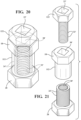
- Figure 20 is an assembled and partially transparent view of a three piece fastener as substantially shown in Fig. 15 with the direction of the first and second screw threads being reversed, this further depicted in the exploded view of Fig. 21 with reversed thread patterns as previously shown in corresponding Fig. 7 (first variant) and Fig. 14 (second variant).
- FIG. 22 an assembled and partially transparent view is generally shown at 130 of a three-piece fastener according to a further embodiment of the present invention.
- the three-piece fastener includes intermediate component 132 and first (bottom) hollow screw 134 and second (top) solid screw 136.
- the intermediate component 132 and first 134 and second 136 fasteners can be constructed of any rigid material not limited to steel, carbon steel or any durable composite (e.g. nylon or polymer) material.
- the screws 134 and 136 are also commonly termed as “threaded bolts” however can include any other suitable configuration for inter-engaging with the intermediate component 132 in the manner described herein.
- Figure 24 provides an axial cutaway view depicting the assembly of Fig. 22 and further showing the first 2 and second 4 layers (see also Fig. 4 ) being secured together, each having aligning apertures again depicted by inner perimeter surfaces 6 and 8, respectively, and through which the stem portion (again at 132) of the intermediate component extends.
- Figure 25 further provides is an exploded axial cutaway view corresponding to Fig. 23 of the three-piece fastener 130.
- the layers 2 and 4 are generally represented and can include any configuration or application not limited in one potential application to such as an attachment fastener for a skate blade to a flange, bracket or other support surface.
- the layers 2 and 4 can correspond to an inner rim or wheel supporting a tire in attachment to a wheel hub such that the present invention serves to provide a durable fastener arrangement which resists loosening in response to vibrations and the like, such as which can be typical of dynamic operating environments.
- the intermediate component 132 includes an enlarged polygonal shaped head, such as which is depicted as a hex head configuration at 138, which is shown proximate its upper open end.
- At least one of the selected screws 134/136 also again termed bolt threads
- hex head 140 associated with the lower or first bolt 134.
- the opposing inner ledge surfaces created by the enlarged hex heads 138 and 140 provide the sandwiching force to the proximate aperture surface perimeter locations of the layers 2/4 in the environmental illustration shown.
- the hex head can again be substituted by any other multi-sided polygonal shape head, not limited to any of a triangular, square, pentagonal or other shape exhibiting a number of interconnected sides, and it is also again envisioned that the polygonal shaped enlarged heads can be reconfigured in other shapes consistent with the use of any tightening or loosening tool.
- the upper or second screw 136 includes a curved and enlarged diameter head 142.
- a tool bit engageable recess (see as including a star profile 144 also known as a Torx style screw by non-limiting example) is formed in the enlarged head 142 to facilitate engagement by a tool bit (not shown) for securing the second (top) screw 136 following pre-threaded engagement of the exterior threads (at 146) of the lower screw 134 within the interior threads (best shown at 148 in Fig. 25 ) of the intermediate component 132.
- the first screw 134 includes a hollow shaft (see generally at 150 in Fig. 23 ) exhibiting a further plurality of interior threads (further at 152) opposite a direction of the first thread pattern 146.
- the second screw 136 exhibits a second exterior thread pattern 154 which is opposite the first pattern and, upon being installed within the other selected one of the opposite ends (depicted as the upper end of the intermediate component 132), results in rotationally inter-engaging of the thread pattern 154 with the matching interior thread pattern 152 of the first screw 134, with loosening of either of the first 134 and second 136 screws being prevented by virtue of their counter-threaded orientation.
- Additional features include the intermediate component 132 exhibiting an upper end proximate undercut recess, see annular inner rim surface 156 communicated with undercut ledge 158, this for receiving and seating the enlarged head 142 of the second fastener 136 in the shown in Figs. 22 and 24 .
- a circular inner perimeter (see at 160) is configured in the undercut recess for communicating the solid extending stem (at 162) of the second fastener 136 within the open interior of the intermediate component 132 and into engagement with the hollow threaded interior 150 of the previously installed first fastener 134 according to the previously described counter-threaded and loosening preventative manner.
Landscapes
- Engineering & Computer Science (AREA)
- General Engineering & Computer Science (AREA)
- Mechanical Engineering (AREA)
- Connection Of Plates (AREA)
- Joining Of Building Structures In Genera (AREA)
- Dowels (AREA)
Claims (9)
- Elément de fixation à trois pièces à verrouillage (10) comprenant :un composant intermédiaire (12) présentant un corps monobloc avec une surface extérieure et une tête de forme polygonale élargie (18), un premier intérieur creux s'étendant entre des extrémités opposées, ledit composant intermédiaire (12) incluant une pluralité de filetages intérieurs (30) disposés dans une première direction et s'étendant depuis une première desdites extrémités opposées, une cavité (34) définie dans ladite tête de forme polygonale élargie (18) et s'étendant vers l'intérieur depuis l'autre desdites extrémités opposées et se terminant dans un rebord en contre-dépouille (36), un périmètre intérieur polygonal (38) configuré dans ladite cavité (34) et faisant communiquer ledit premier intérieur creux avec ledit rebord en contre-dépouille (36) ;un premier élément de fixation (14) présentant un autre corps monobloc avec une première tête élargie (20) et une première tige avec un deuxième intérieur creux, un premier motif de filetage extérieur (24) configuré sur ladite tige s'étendant dans la première direction pour se mettre en prise en rotation avec lesdits filetages intérieurs (30) dudit composant intermédiaire (12) lorsqu'il est installé à travers ladite première extrémité sélectionnée desdites extrémités opposées, ledit deuxième intérieur creux dudit premier élément de fixation (14) présentant une autre pluralité de filetages intérieurs (30) s'étendant dans une deuxième direction opposée à la première direction ; etun deuxième élément de fixation (16) présentant une deuxième tête élargie (22) et une deuxième tige, sur laquelle est configuré un deuxième motif de filetage extérieur (32) s'étendant dans la deuxième direction et, lors de l'installation à travers ladite tête de forme polygonale élargie (18) et dans l'autre extrémité sélectionnée desdites extrémités opposées dudit composant intermédiaire (12), ledit périmètre interne polygonal faisant communiquer ladite deuxième tige dans ledit composant intermédiaire (12) et en prise avec ledit intérieur fileté creux dudit premier élément de fixation précédemment installé (14), ladite deuxième tête élargie (22) étant reçue dans ladite cavité (34) et contre ledit rebord en contre-dépouille (36), ledit deuxième élément de fixation (16) se mettant réciproquement en prise en rotation avec lesdits filetages intérieurs (30) dudit premier élément de fixation (14) dans la deuxième direction, évitant ainsi le desserrage d'un dudit premier ou dudit deuxième élément de fixation (14, 16).
- Elément de fixation à verrouillage (10) selon la revendication 1, ladite tête élargie (20) dudit premier élément de fixation (14) comprenant en outre un certain nombre de côtés interconnectés présentant une forme polygonale.
- Elément de fixation à verrouillage (10) selon la revendication 1, ladite deuxième tête élargie (22) dudit deuxième élément de fixation (16) étant incurvée.
- Elément de fixation à verrouillage (10) selon la revendication 3, comprenant en outre un profil évidé de mise en prise avec une mèche (23) incorporée dans ladite tête élargie (22) dudit deuxième élément de fixation (16).
- Elément de fixation à verrouillage (10) selon la revendication 1, ledit composant intermédiaire (12) et lesdits premier et deuxième éléments de fixation (14, 16) étant chacun construits à partir d'un matériau rigide.
- Elément de fixation à verrouillage (10) selon la revendication 1, comprenant en outre une première et une deuxième couche (2, 4) présentant des ouvertures d'alignement (6, 8) à travers lesquelles ledit composant intermédiaire (12) s'étend, ladite tête de forme polygonale élargie (18) dudit composant intermédiaire (12) et ladite première tête élargie (20) dudit premier élément de fixation (14) comprimant des surfaces de bord opposées desdites couches (2, 4) adjacentes auxdites ouvertures (6, 8).
- Elément de fixation à verrouillage (10) selon la revendication 1, comprenant en outre un périmètre interne circulaire configuré dans ladite cavité pour faire communiquer ladite deuxième tige dudit deuxième élément de fixation (16) dans ledit composant intermédiaire (12) et en prise avec ledit intérieur fileté creux dudit premier élément de fixation précédemment installé (14).
- Elément de fixation à verrouillage (10) selon la revendication 1, ladite tête de forme polygonale élargie (18) dudit composant intermédiaire (12) et ladite première tête élargie (20) dudit premier élément de fixation (14) comprenant en outre des surfaces d'extrémité opposées dudit élément de fixation (10).
- Elément de fixation à verrouillage (10) selon la revendication 1, ladite tête de forme polygonale élargie (18) dudit composant intermédiaire (12) comprenant une tête hexagonale.
Applications Claiming Priority (3)
| Application Number | Priority Date | Filing Date | Title |
|---|---|---|---|
| US201962816964P | 2019-03-12 | 2019-03-12 | |
| US16/507,104 US11168729B2 (en) | 2019-03-12 | 2019-07-10 | Multi-piece anti-vibration locking fastener |
| PCT/US2020/013335 WO2020185297A1 (fr) | 2019-03-12 | 2020-01-13 | Dispositif de fixation anti-vibration à pièces multiples |
Publications (5)
| Publication Number | Publication Date |
|---|---|
| EP3938662A1 EP3938662A1 (fr) | 2022-01-19 |
| EP3938662A4 EP3938662A4 (fr) | 2022-12-21 |
| EP3938662C0 EP3938662C0 (fr) | 2024-10-09 |
| EP3938662B1 true EP3938662B1 (fr) | 2024-10-09 |
| EP3938662B8 EP3938662B8 (fr) | 2024-11-13 |
Family
ID=72424519
Family Applications (1)
| Application Number | Title | Priority Date | Filing Date |
|---|---|---|---|
| EP20771040.1A Active EP3938662B8 (fr) | 2019-03-12 | 2020-01-13 | Dispositif de fixation anti-vibration à pièces multiples |
Country Status (6)
| Country | Link |
|---|---|
| US (1) | US11168729B2 (fr) |
| EP (1) | EP3938662B8 (fr) |
| KR (1) | KR20210138664A (fr) |
| CA (1) | CA3138016A1 (fr) |
| GB (1) | GB2596716B (fr) |
| WO (1) | WO2020185297A1 (fr) |
Families Citing this family (6)
| Publication number | Priority date | Publication date | Assignee | Title |
|---|---|---|---|---|
| CN112303097B (zh) * | 2020-11-05 | 2022-07-29 | 航天精工股份有限公司 | 一种末端防松脱螺纹连接组件及其安装方法 |
| US11486271B1 (en) * | 2021-10-15 | 2022-11-01 | Pratt & Whitney Canada Corp. | Adjustable mount for engine accessory |
| US11746587B1 (en) * | 2022-08-25 | 2023-09-05 | Chad Joseph Hildreth | Doorframe fastening device and method of use |
| EP4386137A1 (fr) * | 2022-12-15 | 2024-06-19 | MR Teknik ApS | Dispositif de verrouillage pour verrouiller une plaque de protection sur une plaque de protection adjacente |
| KR102819250B1 (ko) * | 2023-01-27 | 2025-06-11 | 주식회사 대곤코퍼레이션 | 매뉴얼 위치결정 클램핑 핀 |
| US12534951B1 (en) * | 2025-04-22 | 2026-01-27 | Charles James SPOFFORD | Threaded, booming, cylindrical shims |
Family Cites Families (37)
| Publication number | Priority date | Publication date | Assignee | Title |
|---|---|---|---|---|
| US885544A (en) * | 1907-10-19 | 1908-04-21 | Nestor H Summons | Lock-nut. |
| US932395A (en) * | 1908-03-13 | 1909-08-24 | William F Kenney | Nut-lock. |
| US893081A (en) * | 1908-04-09 | 1908-07-14 | Andrew Kunan | Nut-lock. |
| US1138574A (en) * | 1914-12-21 | 1915-05-04 | O'dell King | Nut and bolt lock. |
| US1357331A (en) * | 1920-05-29 | 1920-11-02 | Fauve Ferdinand Le | Lock-nut |
| US1399191A (en) * | 1921-06-09 | 1921-12-06 | Ernest Inkerman Taylor | Non-removable nut |
| US2956293A (en) | 1958-04-03 | 1960-10-18 | Long Lok Corp | Method of and apparatus for fabricating self-locking threaded fastening members |
| US3222977A (en) | 1963-11-05 | 1965-12-14 | Rudolph M Vaughn | Three piece blind fastener |
| US4043239A (en) * | 1976-01-16 | 1977-08-23 | General Motors Corporation | Shim nut and screw bolt assembly |
| US4253509A (en) * | 1979-04-06 | 1981-03-03 | Collet James R | Theft deterrent locking nut |
| IL72940A0 (en) | 1984-09-14 | 1984-12-31 | Israel Yaniv | Quick-action fastener |
| GB8805757D0 (en) * | 1988-03-10 | 1988-04-07 | Rca Licensing Corp | Protection circuit for horizontal deflection circuits |
| JPH0246308A (ja) * | 1988-08-04 | 1990-02-15 | Wataru Machida | 緩み止めネジ |
| ES2066981T3 (es) * | 1989-08-04 | 1995-03-16 | Du Pont | Composiciones para recubrimiento que contienen catalizadores de 1,3-dialquilimidazol-2-tiona. |
| US5190423A (en) | 1991-02-15 | 1993-03-02 | Ewing Paul E | Locking fastener |
| US6676874B1 (en) | 1992-11-25 | 2004-01-13 | Profil-Verbindungstechnik Gmbh & Co. Kg | Method of sealing a fastener bore |
| JPH074418A (ja) | 1993-04-19 | 1995-01-10 | Hiroshi Oguchi | 物体の固定構造 |
| GB9314428D0 (en) | 1993-07-13 | 1993-08-25 | Rpc Design Ltd | Locking device for lorry wheel nuts |
| US5391032A (en) * | 1993-10-27 | 1995-02-21 | Vassalotti; Michael | Reusable positive bolt locking device |
| US5562379A (en) | 1994-02-16 | 1996-10-08 | Hi-Shear Corporation | Vibration resistant pin and collar fastener |
| US5544991A (en) * | 1995-02-13 | 1996-08-13 | Ford Motor Company | Locking frustrum nut |
| JP3569562B2 (ja) | 1995-03-01 | 2004-09-22 | 本田技研工業株式会社 | ボルトの緩めトルク低減構造および緩め方法 |
| US5855463A (en) * | 1997-09-15 | 1999-01-05 | Newby; John C. | Bolt and nut thread friction locking device with opposite hand threads with a captured spring or spring lock washer |
| WO2002010597A1 (fr) * | 2000-07-28 | 2002-02-07 | Ozawa, Junzo | Element de fixation |
| US20050025607A1 (en) * | 2003-07-31 | 2005-02-03 | Guantonio Michael A. | Interlocking nut assembly to secure a bolt |
| JP4361335B2 (ja) * | 2003-09-17 | 2009-11-11 | イワタボルト株式会社 | ボルトナット機構 |
| US7588386B2 (en) * | 2006-08-30 | 2009-09-15 | Silicon Valley Automation | Leveling and aligning device |
| JP3137118U (ja) | 2007-08-07 | 2007-11-15 | 俊之 倉守 | 強い振動にも緩まないボルトとナット |
| FR2925133B1 (fr) | 2007-12-13 | 2013-06-28 | Itw De France | Attache de fixation d'un sur-tapis a un tapis |
| JP2009204153A (ja) | 2008-02-27 | 2009-09-10 | Toshiyuki Kuramori | 強い振動にも緩まないネジ |
| US8113754B2 (en) * | 2008-09-29 | 2012-02-14 | The Boeing Company | Fastener system with positive retention mechanism |
| JP2011012693A (ja) * | 2009-06-30 | 2011-01-20 | Shirayama:Kk | 挟持用ねじ |
| US8267630B2 (en) * | 2009-07-13 | 2012-09-18 | United Technologies Corporation | Threaded flanged bushing for fastening applications |
| US8398349B2 (en) * | 2010-08-12 | 2013-03-19 | Allen Forrest Jackson | Locking system and method of using same |
| WO2015054722A1 (fr) | 2013-10-14 | 2015-04-23 | Mahe Falekava F | Dispositif de fixation et de blocage de lacet de chaussure |
| TW202033892A (zh) | 2013-12-17 | 2020-09-16 | 美商海特克優尼克斯股份有限公司 | 用於鎖緊螺紋緊固件之設備 |
| EP3423236B1 (fr) | 2016-03-02 | 2022-08-17 | Hytorc Division Unex Corporation | Fixation filetée comprenant des éléments augmentant le coefficient de frottement |
-
2019
- 2019-07-10 US US16/507,104 patent/US11168729B2/en active Active
-
2020
- 2020-01-13 GB GB2114358.1A patent/GB2596716B/en active Active
- 2020-01-13 EP EP20771040.1A patent/EP3938662B8/fr active Active
- 2020-01-13 WO PCT/US2020/013335 patent/WO2020185297A1/fr not_active Ceased
- 2020-01-13 KR KR1020217032605A patent/KR20210138664A/ko not_active Ceased
- 2020-01-13 CA CA3138016A patent/CA3138016A1/fr active Pending
Also Published As
| Publication number | Publication date |
|---|---|
| GB202114358D0 (en) | 2021-11-24 |
| GB2596716A (en) | 2022-01-05 |
| US20200291982A1 (en) | 2020-09-17 |
| EP3938662A1 (fr) | 2022-01-19 |
| EP3938662B8 (fr) | 2024-11-13 |
| CA3138016A1 (fr) | 2020-09-17 |
| GB2596716B (en) | 2023-03-01 |
| EP3938662A4 (fr) | 2022-12-21 |
| EP3938662C0 (fr) | 2024-10-09 |
| US11168729B2 (en) | 2021-11-09 |
| KR20210138664A (ko) | 2021-11-19 |
| WO2020185297A1 (fr) | 2020-09-17 |
Similar Documents
| Publication | Publication Date | Title |
|---|---|---|
| EP3938662B1 (fr) | Dispositif de fixation anti-vibration à pièces multiples | |
| US11499583B2 (en) | Fastener assembly | |
| US11236778B2 (en) | Multi-piece anti-vibration locking fastener having coaxially arranged inner and outer opposite threaded bolts in combination with successive and opposite threaded profiles within a thickened base layer | |
| US6227782B1 (en) | Self-locking threaded fastener assembly | |
| EP1422428B1 (fr) | Fixation de blocage | |
| US5688091A (en) | Self-locking fastener with captive washer | |
| US11339821B2 (en) | High security fastener with external shroud retainer | |
| US6517301B2 (en) | Fastener assembly including a screw element and a supporting element | |
| EP2419651B1 (fr) | Fixation filetee auto-bloquante | |
| US7497653B2 (en) | Locking fastener assembly | |
| US20190219092A1 (en) | Self-clinching floating fastener | |
| US20210364031A1 (en) | Vibration resistant fastener assembly | |
| CN107073557B (zh) | 一体式自锁螺母 | |
| US20230012354A1 (en) | Multi-piece locking fastener assembly such as for securing a wheel rim to a vehicle hub | |
| WO2023044249A1 (fr) | Ensemble de fixation de verrouillage à pièces multiples, tel que pour fixer une jante de roue à un moyeu de véhicule | |
| WO2010122645A1 (fr) | Rondelle pour boulon | |
| CN223089745U (zh) | 紧固件 | |
| CA2416814C (fr) | Fixation de verrouillage | |
| EP3997349B1 (fr) | Ensemble de fixation et fixation ayant une résistance vibratoire et un couple amélioré pour une correspondance de force de serrage | |
| US20220281423A1 (en) | Wheelchair wheel lock plate assembly | |
| US20250387884A1 (en) | Gyratory socket tool | |
| HK1250500A1 (en) | One-piece self-locking nut | |
| US20060013672A1 (en) | Flex lock nut having an annular recess | |
| JP2006200657A (ja) | 締結構造 | |
| JP2001206003A (ja) | 車輪支持装置 |
Legal Events
| Date | Code | Title | Description |
|---|---|---|---|
| STAA | Information on the status of an ep patent application or granted ep patent |
Free format text: STATUS: THE INTERNATIONAL PUBLICATION HAS BEEN MADE |
|
| PUAI | Public reference made under article 153(3) epc to a published international application that has entered the european phase |
Free format text: ORIGINAL CODE: 0009012 |
|
| STAA | Information on the status of an ep patent application or granted ep patent |
Free format text: STATUS: REQUEST FOR EXAMINATION WAS MADE |
|
| 17P | Request for examination filed |
Effective date: 20211011 |
|
| AK | Designated contracting states |
Kind code of ref document: A1 Designated state(s): AL AT BE BG CH CY CZ DE DK EE ES FI FR GB GR HR HU IE IS IT LI LT LU LV MC MK MT NL NO PL PT RO RS SE SI SK SM TR |
|
| DAV | Request for validation of the european patent (deleted) | ||
| DAX | Request for extension of the european patent (deleted) | ||
| A4 | Supplementary search report drawn up and despatched |
Effective date: 20221121 |
|
| RIC1 | Information provided on ipc code assigned before grant |
Ipc: F16B 33/02 20060101ALN20221115BHEP Ipc: F16B 33/00 20060101ALN20221115BHEP Ipc: F16B 37/12 20060101ALI20221115BHEP Ipc: F16B 39/02 20060101ALI20221115BHEP Ipc: F16B 39/22 20060101ALI20221115BHEP Ipc: F16B 5/02 20060101AFI20221115BHEP |
|
| REG | Reference to a national code |
Ref country code: DE Ref legal event code: R079 Free format text: PREVIOUS MAIN CLASS: F16B0002060000 Ipc: F16B0005020000 Ref document number: 602020039162 Country of ref document: DE |
|
| GRAP | Despatch of communication of intention to grant a patent |
Free format text: ORIGINAL CODE: EPIDOSNIGR1 |
|
| STAA | Information on the status of an ep patent application or granted ep patent |
Free format text: STATUS: GRANT OF PATENT IS INTENDED |
|
| RIC1 | Information provided on ipc code assigned before grant |
Ipc: F16B 33/02 20060101ALN20240418BHEP Ipc: F16B 33/00 20060101ALN20240418BHEP Ipc: F16B 37/12 20060101ALI20240418BHEP Ipc: F16B 39/02 20060101ALI20240418BHEP Ipc: F16B 39/22 20060101ALI20240418BHEP Ipc: F16B 5/02 20060101AFI20240418BHEP |
|
| INTG | Intention to grant announced |
Effective date: 20240502 |
|
| GRAS | Grant fee paid |
Free format text: ORIGINAL CODE: EPIDOSNIGR3 |
|
| GRAA | (expected) grant |
Free format text: ORIGINAL CODE: 0009210 |
|
| STAA | Information on the status of an ep patent application or granted ep patent |
Free format text: STATUS: THE PATENT HAS BEEN GRANTED |
|
| AK | Designated contracting states |
Kind code of ref document: B1 Designated state(s): AL AT BE BG CH CY CZ DE DK EE ES FI FR GB GR HR HU IE IS IT LI LT LU LV MC MK MT NL NO PL PT RO RS SE SI SK SM TR |
|
| REG | Reference to a national code |
Ref country code: CH Ref legal event code: EP |
|
| REG | Reference to a national code |
Ref country code: CH Ref legal event code: PK Free format text: BERICHTIGUNG B8 Ref country code: DE Ref legal event code: R096 Ref document number: 602020039162 Country of ref document: DE |
|
| REG | Reference to a national code |
Ref country code: IE Ref legal event code: FG4D |
|
| RBV | Designated contracting states (corrected) |
Designated state(s): AL AT BE BG CH CY CZ DE DK EE ES FI FR GR HR HU IE IS IT LI LT LU LV MC MK MT NL NO PL PT RO RS SE SI SK SM TR |
|
| U01 | Request for unitary effect filed |
Effective date: 20241105 |
|
| U07 | Unitary effect registered |
Designated state(s): AT BE BG DE DK EE FI FR IT LT LU LV MT NL PT RO SE SI Effective date: 20241113 |
|
| U20 | Renewal fee for the european patent with unitary effect paid |
Year of fee payment: 6 Effective date: 20241218 |
|
| PG25 | Lapsed in a contracting state [announced via postgrant information from national office to epo] |
Ref country code: IS Free format text: LAPSE BECAUSE OF FAILURE TO SUBMIT A TRANSLATION OF THE DESCRIPTION OR TO PAY THE FEE WITHIN THE PRESCRIBED TIME-LIMIT Effective date: 20250209 Ref country code: HR Free format text: LAPSE BECAUSE OF FAILURE TO SUBMIT A TRANSLATION OF THE DESCRIPTION OR TO PAY THE FEE WITHIN THE PRESCRIBED TIME-LIMIT Effective date: 20241009 |
|
| PG25 | Lapsed in a contracting state [announced via postgrant information from national office to epo] |
Ref country code: ES Free format text: LAPSE BECAUSE OF FAILURE TO SUBMIT A TRANSLATION OF THE DESCRIPTION OR TO PAY THE FEE WITHIN THE PRESCRIBED TIME-LIMIT Effective date: 20241009 |
|
| PG25 | Lapsed in a contracting state [announced via postgrant information from national office to epo] |
Ref country code: NO Free format text: LAPSE BECAUSE OF FAILURE TO SUBMIT A TRANSLATION OF THE DESCRIPTION OR TO PAY THE FEE WITHIN THE PRESCRIBED TIME-LIMIT Effective date: 20250109 |
|
| PG25 | Lapsed in a contracting state [announced via postgrant information from national office to epo] |
Ref country code: GR Free format text: LAPSE BECAUSE OF FAILURE TO SUBMIT A TRANSLATION OF THE DESCRIPTION OR TO PAY THE FEE WITHIN THE PRESCRIBED TIME-LIMIT Effective date: 20250110 |
|
| PG25 | Lapsed in a contracting state [announced via postgrant information from national office to epo] |
Ref country code: PL Free format text: LAPSE BECAUSE OF FAILURE TO SUBMIT A TRANSLATION OF THE DESCRIPTION OR TO PAY THE FEE WITHIN THE PRESCRIBED TIME-LIMIT Effective date: 20241009 |
|
| PG25 | Lapsed in a contracting state [announced via postgrant information from national office to epo] |
Ref country code: RS Free format text: LAPSE BECAUSE OF FAILURE TO SUBMIT A TRANSLATION OF THE DESCRIPTION OR TO PAY THE FEE WITHIN THE PRESCRIBED TIME-LIMIT Effective date: 20250109 |
|
| PG25 | Lapsed in a contracting state [announced via postgrant information from national office to epo] |
Ref country code: SM Free format text: LAPSE BECAUSE OF FAILURE TO SUBMIT A TRANSLATION OF THE DESCRIPTION OR TO PAY THE FEE WITHIN THE PRESCRIBED TIME-LIMIT Effective date: 20241009 |
|
| PG25 | Lapsed in a contracting state [announced via postgrant information from national office to epo] |
Ref country code: SK Free format text: LAPSE BECAUSE OF FAILURE TO SUBMIT A TRANSLATION OF THE DESCRIPTION OR TO PAY THE FEE WITHIN THE PRESCRIBED TIME-LIMIT Effective date: 20241009 |
|
| PG25 | Lapsed in a contracting state [announced via postgrant information from national office to epo] |
Ref country code: CZ Free format text: LAPSE BECAUSE OF FAILURE TO SUBMIT A TRANSLATION OF THE DESCRIPTION OR TO PAY THE FEE WITHIN THE PRESCRIBED TIME-LIMIT Effective date: 20241009 |
|
| PLBE | No opposition filed within time limit |
Free format text: ORIGINAL CODE: 0009261 |
|
| STAA | Information on the status of an ep patent application or granted ep patent |
Free format text: STATUS: NO OPPOSITION FILED WITHIN TIME LIMIT |
|
| REG | Reference to a national code |
Ref country code: CH Ref legal event code: PL |
|
| PG25 | Lapsed in a contracting state [announced via postgrant information from national office to epo] |
Ref country code: MC Free format text: LAPSE BECAUSE OF FAILURE TO SUBMIT A TRANSLATION OF THE DESCRIPTION OR TO PAY THE FEE WITHIN THE PRESCRIBED TIME-LIMIT Effective date: 20241009 |
|
| 26N | No opposition filed |
Effective date: 20250710 |
|
| PG25 | Lapsed in a contracting state [announced via postgrant information from national office to epo] |
Ref country code: CH Free format text: LAPSE BECAUSE OF NON-PAYMENT OF DUE FEES Effective date: 20250131 |
|
| PG25 | Lapsed in a contracting state [announced via postgrant information from national office to epo] |
Ref country code: IE Free format text: LAPSE BECAUSE OF NON-PAYMENT OF DUE FEES Effective date: 20250113 |
|
| U20 | Renewal fee for the european patent with unitary effect paid |
Year of fee payment: 7 Effective date: 20251230 |