EP3939552A1 - Gouttière de jambe destinée au traitement des pieds-bots et d'autres difformités du pied - Google Patents
Gouttière de jambe destinée au traitement des pieds-bots et d'autres difformités du pied Download PDFInfo
- Publication number
- EP3939552A1 EP3939552A1 EP21186491.3A EP21186491A EP3939552A1 EP 3939552 A1 EP3939552 A1 EP 3939552A1 EP 21186491 A EP21186491 A EP 21186491A EP 3939552 A1 EP3939552 A1 EP 3939552A1
- Authority
- EP
- European Patent Office
- Prior art keywords
- joint
- foot
- spring
- monopod
- holding device
- Prior art date
- Legal status (The legal status is an assumption and is not a legal conclusion. Google has not performed a legal analysis and makes no representation as to the accuracy of the status listed.)
- Granted
Links
Images


Classifications
-
- A—HUMAN NECESSITIES
- A61—MEDICAL OR VETERINARY SCIENCE; HYGIENE
- A61F—FILTERS IMPLANTABLE INTO BLOOD VESSELS; PROSTHESES; DEVICES PROVIDING PATENCY TO, OR PREVENTING COLLAPSING OF, TUBULAR STRUCTURES OF THE BODY, e.g. STENTS; ORTHOPAEDIC, NURSING OR CONTRACEPTIVE DEVICES; FOMENTATION; TREATMENT OR PROTECTION OF EYES OR EARS; BANDAGES, DRESSINGS OR ABSORBENT PADS; FIRST-AID KITS
- A61F5/00—Orthopaedic methods or devices for non-surgical treatment of bones or joints; Nursing devices ; Anti-rape devices
- A61F5/01—Orthopaedic devices, e.g. long-term immobilising or pressure directing devices for treating broken or deformed bones such as splints, casts or braces
- A61F5/0102—Orthopaedic devices, e.g. long-term immobilising or pressure directing devices for treating broken or deformed bones such as splints, casts or braces specially adapted for correcting deformities of the limbs or for supporting them; Ortheses, e.g. with articulations
- A61F5/0127—Orthopaedic devices, e.g. long-term immobilising or pressure directing devices for treating broken or deformed bones such as splints, casts or braces specially adapted for correcting deformities of the limbs or for supporting them; Ortheses, e.g. with articulations for the feet
-
- A—HUMAN NECESSITIES
- A61—MEDICAL OR VETERINARY SCIENCE; HYGIENE
- A61F—FILTERS IMPLANTABLE INTO BLOOD VESSELS; PROSTHESES; DEVICES PROVIDING PATENCY TO, OR PREVENTING COLLAPSING OF, TUBULAR STRUCTURES OF THE BODY, e.g. STENTS; ORTHOPAEDIC, NURSING OR CONTRACEPTIVE DEVICES; FOMENTATION; TREATMENT OR PROTECTION OF EYES OR EARS; BANDAGES, DRESSINGS OR ABSORBENT PADS; FIRST-AID KITS
- A61F5/00—Orthopaedic methods or devices for non-surgical treatment of bones or joints; Nursing devices ; Anti-rape devices
- A61F5/01—Orthopaedic devices, e.g. long-term immobilising or pressure directing devices for treating broken or deformed bones such as splints, casts or braces
- A61F5/0102—Orthopaedic devices, e.g. long-term immobilising or pressure directing devices for treating broken or deformed bones such as splints, casts or braces specially adapted for correcting deformities of the limbs or for supporting them; Ortheses, e.g. with articulations
- A61F2005/0132—Additional features of the articulation
- A61F2005/0134—Additional features of the articulation with two orthogonal pivots
-
- A—HUMAN NECESSITIES
- A61—MEDICAL OR VETERINARY SCIENCE; HYGIENE
- A61F—FILTERS IMPLANTABLE INTO BLOOD VESSELS; PROSTHESES; DEVICES PROVIDING PATENCY TO, OR PREVENTING COLLAPSING OF, TUBULAR STRUCTURES OF THE BODY, e.g. STENTS; ORTHOPAEDIC, NURSING OR CONTRACEPTIVE DEVICES; FOMENTATION; TREATMENT OR PROTECTION OF EYES OR EARS; BANDAGES, DRESSINGS OR ABSORBENT PADS; FIRST-AID KITS
- A61F5/00—Orthopaedic methods or devices for non-surgical treatment of bones or joints; Nursing devices ; Anti-rape devices
- A61F5/01—Orthopaedic devices, e.g. long-term immobilising or pressure directing devices for treating broken or deformed bones such as splints, casts or braces
- A61F5/0102—Orthopaedic devices, e.g. long-term immobilising or pressure directing devices for treating broken or deformed bones such as splints, casts or braces specially adapted for correcting deformities of the limbs or for supporting them; Ortheses, e.g. with articulations
- A61F2005/0132—Additional features of the articulation
- A61F2005/0151—Additional features of the articulation combining rotational and torsional movements
Definitions
- the invention relates to a monopod for treating clubfoot and other foot deformities.
- a plaster cast is first used to correct the deformity and the corrected deformity is held in place by using a splint to prevent recurrence.
- the feet are held in an outwardly rotated position by means of a rod.
- the splint is applied full-time for three months after the end of cast regression therapy, and then only at night for four years. Fixing both feet with the splint is uncomfortable for children and parents, especially as the children get older.
- the EP 1 998 726 B1 describes an orthosis for treating clubfoot that reduces patient stress and yet fixes the patient's feet in the desired alignment by being fully or partially elastic.
- the orthosis can thus give way somewhat when the patient puts a load on it, which reduces the patient's restriction of movement when wearing the orthosis.
- the DE 10 2012 006 261 B4 discloses an orthosis for treating clubfoot to relieve patient stress and maintain feet in desired alignment, in which means for releasably retaining a patient's feet are articulated at either end of a connecting beam and springs are integrated into the articulations.
- the EP 2 637 612 B1 describes orthopedic ankle devices that attach to only a single leg at a time, giving the wearer a larger leg allow freedom of movement.
- These monopods have a connector between a first portion for connection to a leg and a second portion for connection to a foot.
- the connector includes a first adjustment device that permits adjustment-related relative movement of the first part and the second part about a first device rotation axis.
- the connector further includes a second adjustment device that permits a second adjustment-related relative movement of the first part and the second part about a second device rotation axis.
- the first device axis of rotation substantially corresponds to a dominant anatomical axis of rotation of the subtalar joint and the second axis of device rotation substantially corresponds to a dominant anatomic axis of rotation of the tibiotalar joint.
- the first adjustment device includes a first biasing means for providing a first support force for support when using a user's subtalar joint in an abducted, neutral or adducted position.
- the second adjustment device includes a second biasing means for providing a second support force for support when using a user's tibiotalar joint in a dorsiflexed, neutral, or plantarflexed position.
- the monopod allows movements from the pathological range into the overcorrected range, so that the child can bring the foot back into the clubfoot position, which gives him increased mobility but seems questionable from a therapeutic point of view.
- the movement around the second axis of rotation of the device deviates from the external rotation and is complex to implement structurally.
- the invention is based on the object of creating a monopod that gives the child freedom of movement, which supports the therapy according to the Ponseti method even better and facilitates the structural implementation.
- the monoleg brace according to the invention for the treatment of clubfoot and other foot deformities comprises a first holding device for releasably connecting to a leg of a wearer, a second holding device for releasably connecting to a foot on the same leg of the wearer and a connecting device between the first holding device and the second holding device, wherein the linkage includes a first pivot having a first axis of rotation corresponding to the axis of rotation of the ankle, and the linkage includes a second pivot having a vertically oriented second axis of rotation, whereby the first pivot secures a wearer's foot in dorsiflexion and the second pivot secures the foot of a wearer in an external rotation.
- the monopod according to the invention guides the foot of the wearer or child into a position that is raised relative to the body and rotated outwards. Unlike a static splint, which holds each foot in a fixed position, it allows the foot to move so that the capsules, tendons, etc. are stretched rather than remaining stiff and immobile. At the same time, the wearer is given freedom of movement within an acceptable range.
- the first axis of rotation of the first pivot joint corresponds to the axis of rotation of the ankle joint, which is a simple joint with rotation about a single axis only.
- the second axis of rotation of the second pivot joint is aligned vertically in order to carry out external rotation or abduction of the foot according to the Ponseti method. The flexibility of the foot allows this movement.
- the second Swivel joint can be made structurally simpler and more space-saving than a swivel joint with a device axis of rotation corresponding to the anatomical axis of rotation of the tibiotalar joint.
- the monopod improves the use of the Ponseti method and is structurally simpler and more space-saving.
- the first pivot joint comprises a prestressed first spring device, which loads the first pivot joint in the direction of executing a dorsiflexion of a foot connected to the second holding device and/or the second pivot joint comprises a prestressed second spring device, which loads the second pivot joint in the direction the execution of an external rotation of a foot connected to the second holding device.
- the foot is pressed into dorsiflexion and/or external rotation under pretension by the first spring device and/or the second spring device.
- the tendons and capsules are stretched in a way that is comfortable for the child because the feet are not rigidly connected to each other by a splint.
- the foot is pushed into the overcorrection position when body tension is released because the child is sleeping or distracted.
- the child suddenly wants to move this is possible against the action of the first spring device and/or the second spring device.
- the first spring device is a first spring device with adjustable preload and/or the second spring device is a second spring device with adjustable preload.
- the adjustability allows the preload to be adapted to the age and resistance of the respective wearer.
- the first spring device is a first spiral spring and/or the second spring device is a second spiral spring.
- the first spiral spring is a first flat strip spring and/or the second spiral spring is a second flat strip spring.
- the first rotary joint comprises a first gear wheel with a central, first external polygon connected to it and a first bearing bore, a first axis of rotation inserted into the first bearing bore and into further first bearing bores of the two first joint parts of the first rotary joint,
- the first spiral spring has a first spring end positively held on the first external polygon and a second spring end held on a first joint part, and a first grub screw meshing with the first gear wheel is screwed into a first threaded bore in the other first joint part with a first tool attack, whereby by means of a tool attached to the first tool attack Tool rotatable the first gear and the first spiral spring can be prestressed to different extents.
- the second rotary joint comprises a second gear wheel with a central second external polygon connected to it and a second bearing bore, a second axis of rotation inserted into the second bearing bore and into further second bearing bores of the two second joint parts of the second rotary joint,
- the second spiral spring has a first spring end positively held on the second external polygon and a second spring end held on a second joint part, and a second grub screw meshing with the second gear wheel is screwed into a second threaded bore in the other second joint part with a second tool attack, whereby by means of a tool attached to the second tool attack Tool rotates the second gear wheel and the second spiral spring in can be prestressed to different extents.
- the first pivot joint comprises first rotation angle limitations, which limit rotation of the first pivot joint, so that a foot connected to the second holding device on a leg connected to the first holding device can move between a neutral position and a dorsiflexion with an angle of maximum 55 to 30° , preferably by a maximum of 45° and/or the second rotary joint comprises second rotary angle limitations, which limit the rotary movement of the second rotary joint, so that a foot connected to the second holding device on a leg connected to the first holding device can move between a position parallel to the median plane and a Abduction is movable at an angle of at most 75 to 50 °, preferably at most 65 ° to the median plane. This achieves dorsiflexion and external rotation in the therapeutic range.
- the neutral position is the position the foot is in when it is placed straight on level ground.
- the rotation angle limitations prevent the foot from being moved in the pathological range and entering the clubfoot position.
- first fixing device which is designed to fix the first spring device in at least one position and/or there is a second fixing device which is designed to fix the second spring device in at least one position.
- first fixing device and the second fixing device are designed, the first spring device and the second Determine the spring device in positions in which the first holding device and the second holding device hold a leg and the associated foot in the normal position.
- the first holding device has a shell enclosing the tibia and at least part of the calves. According to a further embodiment, the first holding device is selected from a range of first holding devices with shells of different sizes for legs of different sizes. This enables the monopod to be easily adapted to different body sizes. According to a further embodiment, the first holding device has at least one first strap with a first strap fastener, which is designed to be fixed to the leg of a wearer.
- the second holding device has a receiving plate for supporting the foot.
- the second holding device has, above the receiving plate, a tilting plate which is mounted on the receiving plate so that it can tilt about a horizontal axis and on which the foot can be placed.
- the horizontal axis is oriented in the longitudinal direction of the receiving plate and the tilting plate, ie parallel to the median plane of a support of the monopod whose foot connected to the second holding device is oriented parallel to the median plane.
- the tilting plate tilts the hindfoot into the valgus in its external rotation movement.
- the heel adjusts from an inverted position to an eversion due to its movement anatomy.
- the monopod is provided with the tilting plate, which passively allows the movement.
- the tilting plate is coupled to the holding plate via a third spring device and the third spring device loads the tilting plate in the direction of executing a pronation of a foot placed on the tilting plate.
- the third spring device is arranged between the tilting plate and the holding plate. The tilting plate is coupled to one side of the third spring device and the holding plate is coupled to the other side of the third spring device.
- the third spring device loads the tilting plate in the direction of pronation of a foot placed on the tilting plate.
- lifting the foot from the outer edge of the foot is promoted. This causes increased overcorrection of the foot as part of the Ponseti therapy.
- the lateral elevation of the foot also counteracts pes cavus. Overall, the therapeutic effect of the monopod is favorably promoted by this embodiment.
- the third spring device comprises one or more third spiral springs, each of which is supported at one end on the receiving plate and at the other end on the tilting plate.
- the third spiral spring is arranged laterally with respect to the horizontal axis about which the tilting plate is mounted such that it can tilt.
- the helical spring is held on a vertically oriented pin integral with the support plate or the tilting plate.
- a lower end of the third spiral spring is held on the holding plate and/or an upper end of the third spiral spring is held on the tilting plate.
- a lower spring leg is the third spiral spring held on the retaining plate and / or an upper spring leg of the third spiral spring on the tilting plate.
- one or more third spiral springs are arranged only on the lateral side of the horizontal axis.
- the third spring device comprises spiral springs on different sides of the horizontal axis, about which the tilting plate is pivotably mounted, the spring stiffness of the third spiral spring arranged laterally with respect to the horizontal axis being greater than the spring stiffness of the spiral spring arranged medial with respect to the horizontal axis.
- the third spring device comprises at least one torsion spring which is arranged coaxially to the horizontal axis about which the tilting plate is tiltably mounted and which is connected at one end to the receiving plate and at the other end to the tilting plate.
- the torsion spring is a helical spring, spiral spring or conical spring.
- the torsion spring has an outer spring leg connected to the receiving plate and an inner spring leg connected to the tilting plate.
- the torsion spring is arranged on a bearing via which the tilting plate is mounted on the receiving plate such that it can be tilted about a horizontal axis.
- the mounting plate comprises a rear part and a front part, the rear part and the front part being connectable to one another via at least one detachable connection and the rear part and the front part each comprising a bearing in which the horizontal axis of the Tilting plate is stored.
- the movement of the tilting plate in the pathological direction (inversion) is blocked and pronation is limited by the third rotation angle limitations.
- the tilting plate is selected from a range (assortment) of tilting plates of different sizes for feet of different sizes. This enables the monopod to be easily adapted to different body sizes.
- the second holding device comprises at least one second strap with a second strap fastener and/or at least one groove and/or at least one profile and/or at least one snap-on element for releasably holding a foot or a foot optionally with a groove and/or a Profile and/or snap element of a shoe provided with a complementary structural element on the second holding device.
- the first rotary joint comprises a fork part and a lower joint part.
- the fork part can be connected to the first holding device in a simple manner.
- the lower joint part comprises a joint head and a rod-shaped section connected thereto with an elongated hole, and the lower joint part is integrated into one with the rod-shaped section Guide with a bore inserted through two opposite walls, in which a screw passing through the slot is held, which has a screw head on one side of the guide and engages in an internal thread on the other side of the guide, whereby the lower joint part can be locked by tightening the screw can be clamped in different positions in the guide.
- the guide is a hollow profile with a rectangular cross section, into which the rod-shaped section can be inserted.
- the guide is provided with a longitudinal slot between the two opposite walls provided with the bore, which facilitates the clamping of the two walls to the rod-shaped portion by tightening the screw. In this way, an adjustment to different body sizes and a fixation of the monopod in the adjusted position is possible.
- the second rotary joint has an angled bearing plate on the guide, which is inserted through a lateral opening into a chamber of the receiving plate and is mounted therein so that it can rotate about a vertical second axis of rotation.
- top and bottom and “horizontal” and “vertical” refer to the monopod positioned with the first pivot above the second pivot, with the first pivot axis horizontal and the second pivot axis vertical is.
- anatomical designations of the bones and the standardized anatomical position and direction designations e.g. as in Section 3 of the EP 2 637 612 B1 indicated).
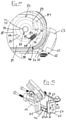
- the monopod 1 includes according to Figures 1 to 6 a first attachment means 2 for detachable connection to a leg of a wearer, a second attachment means 3 for detachable connection to a foot on the same leg of the wearer, and a connection means 4 between the first attachment means 2 and the second attachment means 3.
- the first holding device 2 comprises a holding pin 5 with a rectangular cross-section and a shell 6 fixed thereto, which is designed to partially enclose the tibia and at least part of the calves.
- the retaining pin 5 has a first fastening hole 7 near its lower end, which serves to fasten the first retaining device 2 to the connecting device 4 .
- Padding 8 is fixed to the inside of the shell 6, for example by gluing.
- the padding 8 has portions protruding from the vertical edges of the shell 6 to which straps 9 having buckles, holes, Velcro fasteners or other elements of a strap fastener 10 are attached externally. When the shell 6 is placed on the shin, the straps 9 can be looped around the calf to fix the first attachment means 2 to the wearer's leg.
- the second holding device 3 comprises a receiving plate 11 and a tilting plate 13 mounted thereon such that it can be tilted about a horizontal axis 12.
- the receiving plate 11 and the tilting plate 13 have approximately the shape of the sole of a child's shoe in a plan view.
- the receiving plate 11 includes according to Figures 7 and 8 a rear part 14 and a front part 15, the front part 15 having the shape of a segment of a circle (eg a semicircle) in plan view.
- the rear part 14 has two parallel blind bores 16 on the front face, from the ends of which parallel first threaded bores 17 emanate.
- Two parallel sleeves 18 project from the rear end face of the front part 14 and can be inserted into the blind bores 16 , being guided in the blind bores 16 .
- the front part 15 has two parallel retaining bores 19 which, starting from the front side of the front part 15, which is curved in the shape of a circular arc, extend to the rear ends of the two sleeves 18.
- the two parallel Holding holes 19 have two parallel extensions 20 at the front.
- the front part 15 is inserted with the sleeves 18 in the blind holes 16 and via two fastening screws 21, which are inserted in the two holding holes 19 of the front part 15 and in the first threaded holes 17 of the rear part 14 engage, connected to the rear part 14.
- the heads of the fastening screws 19 are accommodated in the extensions 20 of the retaining bores 19. As a result, the front part 15 and the rear part 14 are kept at a certain distance from one another.
- the receiving plate 11 includes a first recess 22 in the form of a segment of a circular cylinder. This extends between the parallel bores 16, 19 over the front part 15 and the rear part 14 away. From the two ends of the first depression 22 go second depressions 23, 24 in the form of circular cylinder segments of smaller diameter, of which one in the front part 15 and the other in the rear part 14 extends.
- the tilting plate 13 has a protruding circular cylinder segment 25 on the underside.
- the circular cylinder segment 25 occupies more than half of a complete cylinder. From the two end faces of the circular cylinder segment 25 are bearing pins 26, 27 to the front and to the rear.
- the tilting plate 13 is inserted with the circular cylinder segment 25 in the first depression 22 and with the two pins 26, 27 in the second depressions 23, 24 and is pivotably mounted therein.
- the tilting plate 13 is held on the retaining plate in that the bearing journals 26, 27 are surrounded by bearing shells 28, 29, which partially span the second depressions.
- a stop bar 30 protrudes upwards from the upper side of the receiving plate 11 .
- the pivoting of the tilting plate 13 to the lateral side (eversion) is limited by the stop bar 30 .
- the pivoting of the tilting plate 13 towards the median side (inversion) is limited by the fact that its underside rests on the upper side of the receiving plate 11 .
- the circular cylinder segment 25 is mounted in the first depression 22 on its outer circumference. Gaps are formed between the ends of the circular cylinder segment 25 and the first depression 22 .
- the bearing journals 26, 27 are mounted between the second depressions 23, 24 and the bearing shells 28, 29. Between the ends of the bearing pins 26, 27 and the second recesses 23, 24 gaps are formed. The storage of the tilting plate 13 can thus transmit large forces. The displacement of the tilting plate 13 in the longitudinal direction is limited by the gaps.
- the connecting device 4 comprises according to Figures 1 to 6 a first pivot joint 31 having a first pivot axis 32 which corresponds to the pivot axis of the upper ankle joint of a wearer of the monopod 1 .
- the first rotary joint 31 has a fork part 33 at the top and a lower joint part 34 at the bottom.
- the fork part 33 has two fork tines 35 at the top, which are designed to receive the holding pin 5 of the first holding device 2 .
- the forks 35 are connected to one another on one side by a retaining plate 36 which has a second fastening hole 37 which corresponds to the first fastening hole 7 in the retaining pin 5, so that the first and second fastening holes 7, 37 coincide when the retaining pin 5 is inserted between the forks 35.
- the retaining pin 5 means a screw passed through the first and second fastening holes 7, 37 and a nut screwed onto this screw can be fixed to the fork part 33.
- the fork part 33 has according to 9 at the lower end there are two parallel bearing plates 38 through which the first bearing bores 39 extend horizontally.
- the lower joint part 34 has a rod or strip-shaped section 40 at the bottom and a joint head 41 at the upper end of the strip-shaped section 40, which has a circular disk-shaped first depression 42 on a vertical side, which has a bell-shaped first bulge 43 at the bottom. In the first bulge 43 , a horizontal first peg 44 projects outwardly from the base of the first recess 42 .
- the joint head 41 has a first bearing bore 45 in the center of the first depression 42. The joint head 41 can be inserted between the two bearing plates 38 of the fork part 33, so that its first bearing bore 45 aligns with the other first bearing bores 39 in the fork part 33.
- a first toothed wheel 46 is inserted into the first recess 42 and has a first outer polygon 47 protruding from its center on the side facing away from the base of the first recess 42 .
- the first gear 46 has a central first bearing bore 48 which extends through the outer polygon 47 and is aligned with the first bearing bore 39 of the joint head 41 .
- the joint head 41 has a first threaded bore 49 which runs tangentially to the first depression 42 .
- a first grub screw 50 is inserted into the first threaded bore 49 and has a tool grip (eg Allen key) on one end facing the opening of the first threaded bore 49 .
- the Thread of the grub screw 50 engages tangentially in the first recess 42 and is in engagement with the teeth on the outer periphery of the first gear 46.
- a first spiral spring 51 (also referred to as “first spring device 51.1”) is arranged in the first recess 42 and has a first spring end held in a form-fitting manner on the first outer polygon 47 and a second spring end held in a form-fitting manner on the first pin 44.
- first end of the spring is bent in accordance with the shape of the outer polygon 47 and the second end of the spring is bent in the shape of an eyelet for this purpose in accordance with the shape of the pin 44 .
- the first coil spring 51 is constructed and arranged to tend to tilt the fork part 33 forward.
- a first bearing screw 52 is passed through the first bearing bores 39, 45 of the fork part 33 and the lower joint part 34, which rests on the outside of one bearing plate 38 with a first screw head 53 and is screwed into a nut which is on the outside of the other bearing plate 38 of the fork part 33 is present.
- the bearing screw 52 forms the first axis of rotation 32.
- the first rotary joint 31 includes first rotation angle limitations 54, which includes a first and second boundary surface 55, 56 between the two bearing plates 38 of the fork part 33. Furthermore, the first rotation angle limitations 54 include a vertical third boundary surface 57 and a horizontal fourth boundary surface 58 on the joint head 41 of the lower joint part 34. In the example, the boundary surfaces 55, 56, 57, 58 are selected such that when the first boundary surface 55 rests against the third boundary surface 57 the central axis of the joint part 33 forms an angle of 59.85° with the central axis of the lower joint part 45 includes. When the fork part 33 pivots so that the second boundary surface 56 rests against the fourth boundary surface 58, both central axes are aligned vertically and coincide.
- the strip-shaped section 40 of the lower joint part 34 has an elongated hole 59, the longitudinal direction of which is aligned vertically.
- the connecting device 4 comprises a second rotary joint 60 according to 11 and 12 has a horizontal bearing plate 61 on a guide 62 with a vertically aligned guide channel 63 in a rectangular hollow profile 64.
- the hollow profile 64 has a vertical slot 65 on one edge, which extends into the guide channel 63 .
- Above the bearing plate 61 it has a horizontal slot 66 on one side of the vertical slot 65, which extends to the center of the guide channel 63.
- the guide 62 has a horizontal bore 67 on both sides of the guide channel 63.
- the lower joint part 34 is inserted into the guide channel 63 with the strip-shaped section 40 .
- a screw 68 is passed through the bore 67 of the guide 62 and the elongated hole 59 . It is supported with a screw head on one side of the guide and is screwed at the other end into an internal thread of a nut which supports it on the opposite outside of the guide 67 .
- two side walls 69, 70 of the guide 62 can be clamped together slightly, as a result of which the lower joint part 34 is clamped in the guide 62. Clamping side walls 69,70 together is facilitated by slots 65,66.
- the receiving plate 11 has a chamber 71 through a lateral opening 72 at the median and rear edge of the receiving plate 11 through from the outside is accessible.
- the bearing plate 61 engages in the chamber 71 through the lateral opening 72 .
- the bearing plate 61 has a vertical second bearing bore 73 which runs perpendicularly through the chamber 71 .
- the bearing plate 61 has a circular disk-shaped second depression 74 on the underside.
- the second bearing bore 73 runs centrally through the base 75 of the second depression 74.
- the second depression 74 has a bell-shaped second bulge 76 on one side, in which a second pin 77 protrudes from the base 75 of the second recess 74.
- the receiving plate 11 has a vertical second bearing bore 78 which extends below and above the chamber 71 through the walls of the receiving plate 11 which delimit it.
- a second toothed wheel 79 is arranged in the second depression 74 and has a centrally projecting second external polygon 80 on the underside.
- a vertical second bearing bore 81 extends centrally through the second gear wheel 79 and the second external polygon 80.
- a second spiral spring 82 (also referred to as “second spring device 82.1”) is arranged around the second outer polygon 80 below the second gear wheel 79 . This has a third spring end held in a form-fitting manner on the second outer polygon 80 and a fourth spring end held in a form-fitting manner on the second pin 77 . The third end of the spring is bent according to the shape of the second outer polygon 80 and the fourth end of the spring is bent round.
- the second grub screw 84 engages with its screw thread tangentially into the second depression 74 and meshes with the second gear wheel 79.
- the second grub screw 84 has a tool grip (e.g. Allen key) on an end facing outwards from the opening of the second threaded bore 83.
- a second bearing screw 85 is inserted from below into the second bearing bores 73 , 78 , 81 , which passes through the second bearing bores 75 , 78 , 81 and is screwed into a nut resting on the upper side of the receiving plate 11 .
- the head of the bolt and the nut are placed in recesses of the receiving plate 11 so that they do not protrude outward.
- the second bearing screw 85 forms a second axis of rotation 86.
- the second rotary joint 60 comprises according to 11 second rotation angle limitations 87. These are formed by fifth and sixth boundary surfaces 88, 89 of the chamber 71, with the fifth boundary surface 88 at an angle of 90° with the longitudinal axis of the receiving plate 11 (and thus with the median plane) and the sixth boundary surface 89 at an angle of 35° to the longitudinal axis of the receiving plate 11 (and thus to the median plane).
- the bearing plate 61 has a seventh boundary surface 90 and an eighth boundary surface 91 on the outer edge. These are oriented in such a way that when the fifth boundary surface 88 rests against the seventh boundary surface 90, the receiving plate 11 with a foot arranged on it is aligned parallel to the median plane.
- the second spiral spring 82 is designed and arranged in such a way that the receiving plate 11 in the outwardly rotated position is loaded.
- the prestressing of the second spiral spring 82 can be adjusted by means of the second grub screw 84 .
- the tilting plate 13 has according to 7 L-shaped profile rails 92 on the lateral, medial and rear edge, which partially engage over the tilting plate 13 with their unwound ends.
- a shoe with a correspondingly designed edge of the sole can be pushed onto the tilting plate 13 from the front side of the tilting plate 13 . In the pushed-on position, the protruding edge is overlapped by the profile rails 92 . In this position, the shoe can be secured by an additional snap connection or by a click fastener.
- the monopod 1 can be put on by connecting a shoe to the tilt plate 13 and attaching the shell 6 with the straps 9 to the child's calf.
- the spiral springs 51, 82 load the wearer's foot in the direction of dorsal reflection and in the direction of external rotation.
- the rotation angle limitations 54, 87 prevent the foot from being moved into the pathological area and from entering the clubfoot position. This achieves dorsiflexion and external rotation in the therapeutic range.
- the monopod 1 can be adapted to different body sizes by replacing the tilting plate 13 and/or by replacing the first holding device 2 .
- an assortment of tilting plates 13 of different sizes and/or shapes and an assortment of first holding devices 2 with shells 6 and belts 9 of different sizes and/or shapes can be kept available.
- the tilting plate 13 is mounted on the receiving plate 11 such that it can be rotated or tilted about the horizontal axis 12 .
- a third spring device 93 is arranged between the tilting plate 13 and the receiving plate 11 .
- the third spring device 93 consists of a third spiral spring 94 which is supported on the receiving plate 11 at the bottom and on the tilting plate 13 at the top.
- the third spring device 94 is fixed, for example, at its lower end to the receiving plate 11 and/or at its upper end to the tilting plate 13 .
- a lower spring leg of the third spiral spring 94 is inserted into an eyelet or hole on the receiving plate 11 and/or an upper spring leg of the third spiral spring 94 is inserted into an eyelet or hole in the tilting plate.
- the third spring device 94 loads the tilting plate 13 in the direction of executing a pronation of a foot placed on the tilting plate 13 .
- the third spring device 94 can load the tilting plate 12 in such a way that it is aligned at an acute angle to the receiving plate 11 .
- the acute angle is 10° to 20°, for example.
- the third spring device 94 is designed, for example, in such a way that it loads the tilting plate 12 in such a way that, when no foot is placed on it, it does not bear medially against the receiving plate 12, or when a foot is not placed medially against the receiving plate 11.
- the preloading of the tilting plate 13 encourages the foot to be raised from the outer edge of the foot.
Landscapes
- Health & Medical Sciences (AREA)
- Nursing (AREA)
- Orthopedic Medicine & Surgery (AREA)
- Engineering & Computer Science (AREA)
- Biomedical Technology (AREA)
- Heart & Thoracic Surgery (AREA)
- Vascular Medicine (AREA)
- Life Sciences & Earth Sciences (AREA)
- Animal Behavior & Ethology (AREA)
- General Health & Medical Sciences (AREA)
- Public Health (AREA)
- Veterinary Medicine (AREA)
- Orthopedics, Nursing, And Contraception (AREA)
Applications Claiming Priority (1)
| Application Number | Priority Date | Filing Date | Title |
|---|---|---|---|
| DE102020119025 | 2020-07-17 |
Publications (3)
| Publication Number | Publication Date |
|---|---|
| EP3939552A1 true EP3939552A1 (fr) | 2022-01-19 |
| EP3939552C0 EP3939552C0 (fr) | 2023-07-12 |
| EP3939552B1 EP3939552B1 (fr) | 2023-07-12 |
Family
ID=76971781
Family Applications (1)
| Application Number | Title | Priority Date | Filing Date |
|---|---|---|---|
| EP21186491.3A Active EP3939552B1 (fr) | 2020-07-17 | 2021-07-19 | Gouttière de jambe destinée au traitement des pieds-bots et d'autres difformités du pied |
Country Status (1)
| Country | Link |
|---|---|
| EP (1) | EP3939552B1 (fr) |
Cited By (3)
| Publication number | Priority date | Publication date | Assignee | Title |
|---|---|---|---|---|
| DE202022102347U1 (de) | 2022-04-29 | 2023-08-07 | Harald Kujus | Schuh für Kinder mit Fußdeformitäten |
| RU2834717C1 (ru) * | 2023-12-20 | 2025-02-13 | федеральное государственное бюджетное образовательное учреждение высшего образования "Приволжский исследовательский медицинский университет" Министерства здравоохранения Российской Федерации | Ортопедическая шина для лечения эквино-варусных деформаций стоп |
| CN119732805A (zh) * | 2025-03-05 | 2025-04-01 | 南通市第一人民医院 | 一种重症患者护理防碰撞矫正装置 |
Citations (6)
| Publication number | Priority date | Publication date | Assignee | Title |
|---|---|---|---|---|
| US5382225A (en) * | 1992-07-14 | 1995-01-17 | Sutcliffe; Brian L. | Universal night splint |
| US6036665A (en) * | 1998-03-16 | 2000-03-14 | Towsley; Harold E. | Orthopedic foot, ankle and lower leg brace |
| EP1998726B1 (fr) | 2006-03-30 | 2010-09-22 | Semeda Medizinische Instrumente e.K. | Orthese pour traitement des pieds bots |
| EP2637612A2 (fr) | 2010-11-08 | 2013-09-18 | C-Pro Direct Ltd | Dispositifs orthopédiques cheville-pied |
| DE102012006261B4 (de) | 2011-03-29 | 2018-03-29 | Semeda Medizinsche Instumente e.K. | Orthese zur Klumpfußbehandlung |
| US20180271691A1 (en) * | 2017-03-23 | 2018-09-27 | Honda Motor Co., Ltd. | Ankle joint mechanism |
-
2021
- 2021-07-19 EP EP21186491.3A patent/EP3939552B1/fr active Active
Patent Citations (7)
| Publication number | Priority date | Publication date | Assignee | Title |
|---|---|---|---|---|
| US5382225A (en) * | 1992-07-14 | 1995-01-17 | Sutcliffe; Brian L. | Universal night splint |
| US6036665A (en) * | 1998-03-16 | 2000-03-14 | Towsley; Harold E. | Orthopedic foot, ankle and lower leg brace |
| EP1998726B1 (fr) | 2006-03-30 | 2010-09-22 | Semeda Medizinische Instrumente e.K. | Orthese pour traitement des pieds bots |
| EP2637612A2 (fr) | 2010-11-08 | 2013-09-18 | C-Pro Direct Ltd | Dispositifs orthopédiques cheville-pied |
| EP2637612B1 (fr) | 2010-11-08 | 2015-09-02 | C-Pro Direct Ltd | Dispositifs orthopédiques cheville-pied |
| DE102012006261B4 (de) | 2011-03-29 | 2018-03-29 | Semeda Medizinsche Instumente e.K. | Orthese zur Klumpfußbehandlung |
| US20180271691A1 (en) * | 2017-03-23 | 2018-09-27 | Honda Motor Co., Ltd. | Ankle joint mechanism |
Cited By (3)
| Publication number | Priority date | Publication date | Assignee | Title |
|---|---|---|---|---|
| DE202022102347U1 (de) | 2022-04-29 | 2023-08-07 | Harald Kujus | Schuh für Kinder mit Fußdeformitäten |
| RU2834717C1 (ru) * | 2023-12-20 | 2025-02-13 | федеральное государственное бюджетное образовательное учреждение высшего образования "Приволжский исследовательский медицинский университет" Министерства здравоохранения Российской Федерации | Ортопедическая шина для лечения эквино-варусных деформаций стоп |
| CN119732805A (zh) * | 2025-03-05 | 2025-04-01 | 南通市第一人民医院 | 一种重症患者护理防碰撞矫正装置 |
Also Published As
| Publication number | Publication date |
|---|---|
| EP3939552C0 (fr) | 2023-07-12 |
| EP3939552B1 (fr) | 2023-07-12 |
Similar Documents
| Publication | Publication Date | Title |
|---|---|---|
| DE3854651T2 (de) | Gelenkverbindung für orthopädische Kniestütze. | |
| DE69227882T2 (de) | Orthopädisches Gerät mit Mehrfestwinkel | |
| DE68917486T2 (de) | Sportschuh mit Vorrichtung gegen knicken nach innen. | |
| DE60035431T2 (de) | Gelenk für orthopädische knieorthese und das gelenk integrierende knieorthese | |
| DE69316541T2 (de) | Schulterschiene | |
| DE69727479T2 (de) | Winkelkompensationsvorrichtung für gelenkstütze | |
| DE69616629T2 (de) | Abduktionsschiene für Schulter und Arm | |
| EP1588678B1 (fr) | Orthèse de hanche modulaire | |
| DE69013614T2 (de) | Gliedstütze oder Schiene. | |
| EP3378448B1 (fr) | Orthèse du genou modulaire | |
| EP1998726B1 (fr) | Orthese pour traitement des pieds bots | |
| DE2750755A1 (de) | Fuss-orthese | |
| WO2019101910A1 (fr) | Orthèse d'extrémité, en particulier orthèse de genou | |
| EP3939552B1 (fr) | Gouttière de jambe destinée au traitement des pieds-bots et d'autres difformités du pied | |
| DE102008049854B4 (de) | Orthese zur Korrektur von Fehlstellungen und zum Redressieren von Körpergliedern in Abduktions- oder Adduktionsrichtung | |
| WO2019106153A1 (fr) | Dispositif de réglage et orthèse pourvue d'un dispositif de réglage | |
| DE1147711B (de) | Abduktionsschiene | |
| WO2014173512A1 (fr) | Orthèse de décharge | |
| EP0751754B1 (fr) | Orthese pour le genou | |
| DE9100531U1 (de) | Fußorthese | |
| DE10114032B4 (de) | Orthese | |
| DE102021100829B3 (de) | Fußstützensystem für ein Fußmodul eines Rehabilitationsmechanismus | |
| DE102009056321A1 (de) | Orthesengelenk | |
| DE2651469A1 (de) | Klumpfussnachtschiene | |
| DE102016105353B4 (de) | Orthese |
Legal Events
| Date | Code | Title | Description |
|---|---|---|---|
| PUAI | Public reference made under article 153(3) epc to a published international application that has entered the european phase |
Free format text: ORIGINAL CODE: 0009012 |
|
| STAA | Information on the status of an ep patent application or granted ep patent |
Free format text: STATUS: THE APPLICATION HAS BEEN PUBLISHED |
|
| AK | Designated contracting states |
Kind code of ref document: A1 Designated state(s): AL AT BE BG CH CY CZ DE DK EE ES FI FR GB GR HR HU IE IS IT LI LT LU LV MC MK MT NL NO PL PT RO RS SE SI SK SM TR |
|
| RAP1 | Party data changed (applicant data changed or rights of an application transferred) |
Owner name: JOHANNSEN, PETRA |
|
| STAA | Information on the status of an ep patent application or granted ep patent |
Free format text: STATUS: REQUEST FOR EXAMINATION WAS MADE |
|
| 17P | Request for examination filed |
Effective date: 20220719 |
|
| RBV | Designated contracting states (corrected) |
Designated state(s): AL AT BE BG CH CY CZ DE DK EE ES FI FR GB GR HR HU IE IS IT LI LT LU LV MC MK MT NL NO PL PT RO RS SE SI SK SM TR |
|
| GRAP | Despatch of communication of intention to grant a patent |
Free format text: ORIGINAL CODE: EPIDOSNIGR1 |
|
| STAA | Information on the status of an ep patent application or granted ep patent |
Free format text: STATUS: GRANT OF PATENT IS INTENDED |
|
| INTG | Intention to grant announced |
Effective date: 20230309 |
|
| GRAS | Grant fee paid |
Free format text: ORIGINAL CODE: EPIDOSNIGR3 |
|
| GRAA | (expected) grant |
Free format text: ORIGINAL CODE: 0009210 |
|
| STAA | Information on the status of an ep patent application or granted ep patent |
Free format text: STATUS: THE PATENT HAS BEEN GRANTED |
|
| AK | Designated contracting states |
Kind code of ref document: B1 Designated state(s): AL AT BE BG CH CY CZ DE DK EE ES FI FR GB GR HR HU IE IS IT LI LT LU LV MC MK MT NL NO PL PT RO RS SE SI SK SM TR |
|
| REG | Reference to a national code |
Ref country code: CH Ref legal event code: EP |
|
| REG | Reference to a national code |
Ref country code: IE Ref legal event code: FG4D Free format text: LANGUAGE OF EP DOCUMENT: GERMAN |
|
| REG | Reference to a national code |
Ref country code: DE Ref legal event code: R096 Ref document number: 502021000991 Country of ref document: DE |
|
| U01 | Request for unitary effect filed |
Effective date: 20230811 |
|
| U07 | Unitary effect registered |
Designated state(s): AT BE BG DE DK EE FI FR IT LT LU LV MT NL PT SE SI Effective date: 20230818 |
|
| U20 | Renewal fee for the european patent with unitary effect paid |
Year of fee payment: 3 Effective date: 20230831 |
|
| REG | Reference to a national code |
Ref country code: LT Ref legal event code: MG9D |
|
| PG25 | Lapsed in a contracting state [announced via postgrant information from national office to epo] |
Ref country code: ES Free format text: LAPSE BECAUSE OF FAILURE TO SUBMIT A TRANSLATION OF THE DESCRIPTION OR TO PAY THE FEE WITHIN THE PRESCRIBED TIME-LIMIT Effective date: 20230712 |
|
| PG25 | Lapsed in a contracting state [announced via postgrant information from national office to epo] |
Ref country code: IS Free format text: LAPSE BECAUSE OF FAILURE TO SUBMIT A TRANSLATION OF THE DESCRIPTION OR TO PAY THE FEE WITHIN THE PRESCRIBED TIME-LIMIT Effective date: 20231112 |
|
| PG25 | Lapsed in a contracting state [announced via postgrant information from national office to epo] |
Ref country code: RS Free format text: LAPSE BECAUSE OF FAILURE TO SUBMIT A TRANSLATION OF THE DESCRIPTION OR TO PAY THE FEE WITHIN THE PRESCRIBED TIME-LIMIT Effective date: 20230712 Ref country code: NO Free format text: LAPSE BECAUSE OF FAILURE TO SUBMIT A TRANSLATION OF THE DESCRIPTION OR TO PAY THE FEE WITHIN THE PRESCRIBED TIME-LIMIT Effective date: 20231012 Ref country code: IS Free format text: LAPSE BECAUSE OF FAILURE TO SUBMIT A TRANSLATION OF THE DESCRIPTION OR TO PAY THE FEE WITHIN THE PRESCRIBED TIME-LIMIT Effective date: 20231112 Ref country code: HR Free format text: LAPSE BECAUSE OF FAILURE TO SUBMIT A TRANSLATION OF THE DESCRIPTION OR TO PAY THE FEE WITHIN THE PRESCRIBED TIME-LIMIT Effective date: 20230712 Ref country code: ES Free format text: LAPSE BECAUSE OF FAILURE TO SUBMIT A TRANSLATION OF THE DESCRIPTION OR TO PAY THE FEE WITHIN THE PRESCRIBED TIME-LIMIT Effective date: 20230712 |
|
| PG25 | Lapsed in a contracting state [announced via postgrant information from national office to epo] |
Ref country code: PL Free format text: LAPSE BECAUSE OF FAILURE TO SUBMIT A TRANSLATION OF THE DESCRIPTION OR TO PAY THE FEE WITHIN THE PRESCRIBED TIME-LIMIT Effective date: 20230712 |
|
| REG | Reference to a national code |
Ref country code: DE Ref legal event code: R097 Ref document number: 502021000991 Country of ref document: DE |
|
| PG25 | Lapsed in a contracting state [announced via postgrant information from national office to epo] |
Ref country code: SM Free format text: LAPSE BECAUSE OF FAILURE TO SUBMIT A TRANSLATION OF THE DESCRIPTION OR TO PAY THE FEE WITHIN THE PRESCRIBED TIME-LIMIT Effective date: 20230712 Ref country code: RO Free format text: LAPSE BECAUSE OF FAILURE TO SUBMIT A TRANSLATION OF THE DESCRIPTION OR TO PAY THE FEE WITHIN THE PRESCRIBED TIME-LIMIT Effective date: 20230712 Ref country code: CZ Free format text: LAPSE BECAUSE OF FAILURE TO SUBMIT A TRANSLATION OF THE DESCRIPTION OR TO PAY THE FEE WITHIN THE PRESCRIBED TIME-LIMIT Effective date: 20230712 Ref country code: SK Free format text: LAPSE BECAUSE OF FAILURE TO SUBMIT A TRANSLATION OF THE DESCRIPTION OR TO PAY THE FEE WITHIN THE PRESCRIBED TIME-LIMIT Effective date: 20230712 Ref country code: MC Free format text: LAPSE BECAUSE OF FAILURE TO SUBMIT A TRANSLATION OF THE DESCRIPTION OR TO PAY THE FEE WITHIN THE PRESCRIBED TIME-LIMIT Effective date: 20230712 |
|
| PLBE | No opposition filed within time limit |
Free format text: ORIGINAL CODE: 0009261 |
|
| STAA | Information on the status of an ep patent application or granted ep patent |
Free format text: STATUS: NO OPPOSITION FILED WITHIN TIME LIMIT |
|
| 26N | No opposition filed |
Effective date: 20240415 |
|
| U20 | Renewal fee for the european patent with unitary effect paid |
Year of fee payment: 4 Effective date: 20240718 |
|
| REG | Reference to a national code |
Ref country code: CH Ref legal event code: PL |
|
| PG25 | Lapsed in a contracting state [announced via postgrant information from national office to epo] |
Ref country code: CH Free format text: LAPSE BECAUSE OF NON-PAYMENT OF DUE FEES Effective date: 20240731 |
|
| PG25 | Lapsed in a contracting state [announced via postgrant information from national office to epo] |
Ref country code: CY Free format text: LAPSE BECAUSE OF FAILURE TO SUBMIT A TRANSLATION OF THE DESCRIPTION OR TO PAY THE FEE WITHIN THE PRESCRIBED TIME-LIMIT; INVALID AB INITIO Effective date: 20210719 |
|
| PG25 | Lapsed in a contracting state [announced via postgrant information from national office to epo] |
Ref country code: HU Free format text: LAPSE BECAUSE OF FAILURE TO SUBMIT A TRANSLATION OF THE DESCRIPTION OR TO PAY THE FEE WITHIN THE PRESCRIBED TIME-LIMIT; INVALID AB INITIO Effective date: 20210719 |
|
| U20 | Renewal fee for the european patent with unitary effect paid |
Year of fee payment: 5 Effective date: 20250717 |
|
| PG25 | Lapsed in a contracting state [announced via postgrant information from national office to epo] |
Ref country code: GR Free format text: LAPSE BECAUSE OF FAILURE TO SUBMIT A TRANSLATION OF THE DESCRIPTION OR TO PAY THE FEE WITHIN THE PRESCRIBED TIME-LIMIT; INVALID AB INITIO Effective date: 20210719 |
|
| PGFP | Annual fee paid to national office [announced via postgrant information from national office to epo] |
Ref country code: GB Payment date: 20250722 Year of fee payment: 5 |
|
| PGFP | Annual fee paid to national office [announced via postgrant information from national office to epo] |
Ref country code: IE Payment date: 20250724 Year of fee payment: 5 |
|
| PG25 | Lapsed in a contracting state [announced via postgrant information from national office to epo] |
Ref country code: TR Free format text: LAPSE BECAUSE OF FAILURE TO SUBMIT A TRANSLATION OF THE DESCRIPTION OR TO PAY THE FEE WITHIN THE PRESCRIBED TIME-LIMIT Effective date: 20230712 |