EP3940202B1 - Labyrinthbarriere mit elementen aus einem formgedächtnismaterial - Google Patents
Labyrinthbarriere mit elementen aus einem formgedächtnismaterial Download PDFInfo
- Publication number
- EP3940202B1 EP3940202B1 EP21185337.9A EP21185337A EP3940202B1 EP 3940202 B1 EP3940202 B1 EP 3940202B1 EP 21185337 A EP21185337 A EP 21185337A EP 3940202 B1 EP3940202 B1 EP 3940202B1
- Authority
- EP
- European Patent Office
- Prior art keywords
- shape memory
- members
- energy state
- memory material
- another
- Prior art date
- Legal status (The legal status is an assumption and is not a legal conclusion. Google has not performed a legal analysis and makes no representation as to the accuracy of the status listed.)
- Active
Links
Images



Classifications
-
- F—MECHANICAL ENGINEERING; LIGHTING; HEATING; WEAPONS; BLASTING
- F16—ENGINEERING ELEMENTS AND UNITS; GENERAL MEASURES FOR PRODUCING AND MAINTAINING EFFECTIVE FUNCTIONING OF MACHINES OR INSTALLATIONS; THERMAL INSULATION IN GENERAL
- F16J—PISTONS; CYLINDERS; SEALINGS
- F16J15/00—Sealings
- F16J15/44—Free-space packings
- F16J15/447—Labyrinth packings
-
- F—MECHANICAL ENGINEERING; LIGHTING; HEATING; WEAPONS; BLASTING
- F01—MACHINES OR ENGINES IN GENERAL; ENGINE PLANTS IN GENERAL; STEAM ENGINES
- F01D—NON-POSITIVE DISPLACEMENT MACHINES OR ENGINES, e.g. STEAM TURBINES
- F01D11/00—Preventing or minimising internal leakage of working-fluid, e.g. between stages
- F01D11/02—Preventing or minimising internal leakage of working-fluid, e.g. between stages by non-contact sealings, e.g. of labyrinth type
-
- F—MECHANICAL ENGINEERING; LIGHTING; HEATING; WEAPONS; BLASTING
- F01—MACHINES OR ENGINES IN GENERAL; ENGINE PLANTS IN GENERAL; STEAM ENGINES
- F01D—NON-POSITIVE DISPLACEMENT MACHINES OR ENGINES, e.g. STEAM TURBINES
- F01D11/00—Preventing or minimising internal leakage of working-fluid, e.g. between stages
- F01D11/02—Preventing or minimising internal leakage of working-fluid, e.g. between stages by non-contact sealings, e.g. of labyrinth type
- F01D11/025—Seal clearance control; Floating assembly; Adaptation means to differential thermal dilatations
-
- F—MECHANICAL ENGINEERING; LIGHTING; HEATING; WEAPONS; BLASTING
- F01—MACHINES OR ENGINES IN GENERAL; ENGINE PLANTS IN GENERAL; STEAM ENGINES
- F01D—NON-POSITIVE DISPLACEMENT MACHINES OR ENGINES, e.g. STEAM TURBINES
- F01D25/00—Component parts, details, or accessories, not provided for in, or of interest apart from, other groups
- F01D25/005—Selecting particular materials
-
- F—MECHANICAL ENGINEERING; LIGHTING; HEATING; WEAPONS; BLASTING
- F02—COMBUSTION ENGINES; HOT-GAS OR COMBUSTION-PRODUCT ENGINE PLANTS
- F02C—GAS-TURBINE PLANTS; AIR INTAKES FOR JET-PROPULSION PLANTS; CONTROLLING FUEL SUPPLY IN AIR-BREATHING JET-PROPULSION PLANTS
- F02C7/00—Features, components parts, details or accessories, not provided for in, or of interest apart form groups F02C1/00 - F02C6/00; Air intakes for jet-propulsion plants
- F02C7/24—Heat or noise insulation
- F02C7/25—Fire protection or prevention
-
- F—MECHANICAL ENGINEERING; LIGHTING; HEATING; WEAPONS; BLASTING
- F02—COMBUSTION ENGINES; HOT-GAS OR COMBUSTION-PRODUCT ENGINE PLANTS
- F02C—GAS-TURBINE PLANTS; AIR INTAKES FOR JET-PROPULSION PLANTS; CONTROLLING FUEL SUPPLY IN AIR-BREATHING JET-PROPULSION PLANTS
- F02C7/00—Features, components parts, details or accessories, not provided for in, or of interest apart form groups F02C1/00 - F02C6/00; Air intakes for jet-propulsion plants
- F02C7/28—Arrangement of seals
-
- F—MECHANICAL ENGINEERING; LIGHTING; HEATING; WEAPONS; BLASTING
- F02—COMBUSTION ENGINES; HOT-GAS OR COMBUSTION-PRODUCT ENGINE PLANTS
- F02K—JET-PROPULSION PLANTS
- F02K1/00—Plants characterised by the form or arrangement of the jet pipe or nozzle; Jet pipes or nozzles peculiar thereto
- F02K1/54—Nozzles having means for reversing jet thrust
-
- F—MECHANICAL ENGINEERING; LIGHTING; HEATING; WEAPONS; BLASTING
- F02—COMBUSTION ENGINES; HOT-GAS OR COMBUSTION-PRODUCT ENGINE PLANTS
- F02K—JET-PROPULSION PLANTS
- F02K1/00—Plants characterised by the form or arrangement of the jet pipe or nozzle; Jet pipes or nozzles peculiar thereto
- F02K1/54—Nozzles having means for reversing jet thrust
- F02K1/64—Reversing fan flow
-
- F—MECHANICAL ENGINEERING; LIGHTING; HEATING; WEAPONS; BLASTING
- F02—COMBUSTION ENGINES; HOT-GAS OR COMBUSTION-PRODUCT ENGINE PLANTS
- F02K—JET-PROPULSION PLANTS
- F02K1/00—Plants characterised by the form or arrangement of the jet pipe or nozzle; Jet pipes or nozzles peculiar thereto
- F02K1/78—Other construction of jet pipes
- F02K1/80—Couplings or connections
- F02K1/805—Sealing devices therefor, e.g. for movable parts of jet pipes or nozzle flaps
-
- F—MECHANICAL ENGINEERING; LIGHTING; HEATING; WEAPONS; BLASTING
- F03—MACHINES OR ENGINES FOR LIQUIDS; WIND, SPRING, OR WEIGHT MOTORS; PRODUCING MECHANICAL POWER OR A REACTIVE PROPULSIVE THRUST, NOT OTHERWISE PROVIDED FOR
- F03G—SPRING, WEIGHT, INERTIA OR LIKE MOTORS; MECHANICAL-POWER PRODUCING DEVICES OR MECHANISMS, NOT OTHERWISE PROVIDED FOR OR USING ENERGY SOURCES NOT OTHERWISE PROVIDED FOR
- F03G7/00—Mechanical-power-producing mechanisms, not otherwise provided for or using energy sources not otherwise provided for
- F03G7/06—Mechanical-power-producing mechanisms, not otherwise provided for or using energy sources not otherwise provided for using expansion or contraction of bodies due to heating, cooling, moistening, drying or the like
- F03G7/061—Mechanical-power-producing mechanisms, not otherwise provided for or using energy sources not otherwise provided for using expansion or contraction of bodies due to heating, cooling, moistening, drying or the like characterised by the actuating element
- F03G7/0614—Mechanical-power-producing mechanisms, not otherwise provided for or using energy sources not otherwise provided for using expansion or contraction of bodies due to heating, cooling, moistening, drying or the like characterised by the actuating element using shape memory elements
-
- F—MECHANICAL ENGINEERING; LIGHTING; HEATING; WEAPONS; BLASTING
- F03—MACHINES OR ENGINES FOR LIQUIDS; WIND, SPRING, OR WEIGHT MOTORS; PRODUCING MECHANICAL POWER OR A REACTIVE PROPULSIVE THRUST, NOT OTHERWISE PROVIDED FOR
- F03G—SPRING, WEIGHT, INERTIA OR LIKE MOTORS; MECHANICAL-POWER PRODUCING DEVICES OR MECHANISMS, NOT OTHERWISE PROVIDED FOR OR USING ENERGY SOURCES NOT OTHERWISE PROVIDED FOR
- F03G7/00—Mechanical-power-producing mechanisms, not otherwise provided for or using energy sources not otherwise provided for
- F03G7/06—Mechanical-power-producing mechanisms, not otherwise provided for or using energy sources not otherwise provided for using expansion or contraction of bodies due to heating, cooling, moistening, drying or the like
- F03G7/061—Mechanical-power-producing mechanisms, not otherwise provided for or using energy sources not otherwise provided for using expansion or contraction of bodies due to heating, cooling, moistening, drying or the like characterised by the actuating element
- F03G7/0614—Mechanical-power-producing mechanisms, not otherwise provided for or using energy sources not otherwise provided for using expansion or contraction of bodies due to heating, cooling, moistening, drying or the like characterised by the actuating element using shape memory elements
- F03G7/06146—Torque tubes or torsion bars
-
- F—MECHANICAL ENGINEERING; LIGHTING; HEATING; WEAPONS; BLASTING
- F16—ENGINEERING ELEMENTS AND UNITS; GENERAL MEASURES FOR PRODUCING AND MAINTAINING EFFECTIVE FUNCTIONING OF MACHINES OR INSTALLATIONS; THERMAL INSULATION IN GENERAL
- F16J—PISTONS; CYLINDERS; SEALINGS
- F16J15/00—Sealings
- F16J15/16—Sealings between relatively-moving surfaces
- F16J15/164—Sealings between relatively-moving surfaces the sealing action depending on movements; pressure difference, temperature or presence of leaking fluid
-
- F—MECHANICAL ENGINEERING; LIGHTING; HEATING; WEAPONS; BLASTING
- F05—INDEXING SCHEMES RELATING TO ENGINES OR PUMPS IN VARIOUS SUBCLASSES OF CLASSES F01-F04
- F05D—INDEXING SCHEME FOR ASPECTS RELATING TO NON-POSITIVE-DISPLACEMENT MACHINES OR ENGINES, GAS-TURBINES OR JET-PROPULSION PLANTS
- F05D2240/00—Components
- F05D2240/55—Seals
-
- F—MECHANICAL ENGINEERING; LIGHTING; HEATING; WEAPONS; BLASTING
- F05—INDEXING SCHEMES RELATING TO ENGINES OR PUMPS IN VARIOUS SUBCLASSES OF CLASSES F01-F04
- F05D—INDEXING SCHEME FOR ASPECTS RELATING TO NON-POSITIVE-DISPLACEMENT MACHINES OR ENGINES, GAS-TURBINES OR JET-PROPULSION PLANTS
- F05D2300/00—Materials; Properties thereof
- F05D2300/50—Intrinsic material properties or characteristics
- F05D2300/505—Shape memory behaviour
-
- Y—GENERAL TAGGING OF NEW TECHNOLOGICAL DEVELOPMENTS; GENERAL TAGGING OF CROSS-SECTIONAL TECHNOLOGIES SPANNING OVER SEVERAL SECTIONS OF THE IPC; TECHNICAL SUBJECTS COVERED BY FORMER USPC CROSS-REFERENCE ART COLLECTIONS [XRACs] AND DIGESTS
- Y02—TECHNOLOGIES OR APPLICATIONS FOR MITIGATION OR ADAPTATION AGAINST CLIMATE CHANGE
- Y02T—CLIMATE CHANGE MITIGATION TECHNOLOGIES RELATED TO TRANSPORTATION
- Y02T50/00—Aeronautics or air transport
- Y02T50/60—Efficient propulsion technologies, e.g. for aircraft
Definitions
- the present disclosure relates to a system comprising a labyrinth barrier. More particularly, the present disclosure is directed towards a labyrinth barrier having two or more members that are constructed at least in part of a shape memory material.
- a labyrinth barrier operates as a non-contact seal between two adjacent compartments.
- the labyrinth barrier when used in a thrust reverser for an aircraft, creates a torturous pathway that restricts fluid located in an engine core compartment from flowing into another thrust reverser compartment.
- the labyrinth barrier creates an alternate circumferential pathway that is of lower resistance when compared to the axial pathway that otherwise connects the thrust reverser compartments. Therefore, the fluid naturally flows from the engine core compartment towards the alternate pathway provided by the labyrinth barrier.
- Alternate configurations rely primarily on vortex formation as opposed to flow redirection.
- the labyrinth barrier includes multiple elongated members arranged in a staggered pattern. It is to be appreciated that a clearance exists between the members, which creates an imperfect seal. The clearance allows the members to interlock with one another without contacting one another or creating damage when the labyrinth barrier is opened or closed. However, if the clearance is too large, then there is less flow restriction, which in turn reduces the overall effectiveness of the labyrinth barrier. In contrast, if the clearance is too small, then other issues may arise. For example, the individual members of the labyrinth barrier may rub or otherwise contact one another. The contact between the members may create structural issues as well as compromise the effectiveness of the labyrinth barrier.
- a turkey feather seal may be used instead of a labyrinth barrier in a thrust reverser.
- a turkey feather seal includes multiple flexible metal segments that overlap one another. The segments deform slightly and directly contact the engine exhaust. However, the environment around the engine is very dynamic and experiences a significant amount of vibration, which in turn adversely affects the turkey feather seal.
- US2014/248120A1 in an abstract states that "An improved seal assembly for use with a combustion liner assembly is employed with a gas turbine engine so as to control fluid flow.
- the seal assembly has a bi-metal sealing member that is affixed to a first surface that is proximal to a second perpendicular surface that is not in contact with the first surface, thus providing a potential fluid flow path.
- the bi-metal sealing member Upon heating, the bi-metal sealing member "uncoils" contacting the second perpendicular surface, thus blocking the flowpath between the two surfaces.
- Various metals may be provided to provide predetermined sealing characteristics.”
- EP2116621A2 in an abstract states that "A high temperature component having an actuator body 201 including an actuatable portion comprising a shape memory alloy containing one more of Ni, Al, Nb, Ti and Ta and a platinum-group metal.
- the shape memory alloy has an altered geometry at a predetermined temperature.
- the actuator body 201 is also capable of operation in and is resistant to high temperature oxidizing atmospheres.
- a method for forming an actuator and a method for high temperature control are also disclosed.”
- JPH0438140A in an abstract states that "PURPOSE: To constitute a holder integrally on the fixed side of shaft-through part of an electric rotating machine by composing a labyrinth seal piece of a shape memory alloy.
- CONSTITUTION A plurality of fixed side labyrinth seal pieces 1 made of shape memory alloy are planted on a holder 3 whereas a plurality of rotary side labyrinth seal pieces 2 made of shape memory alloy are planted on a shaft 4, and then the labyrinth seal pieces 1, 2 are cooled to be bent axially.
- the integrally constituted holder 3 is then inserted, axially from the right side, into a shaft 1 with the fixed side labyrinth seal piece 1 being bent thus securing the holder in place.
- JPH01 146070U in a translation of its title refers to a labyrinth seal.
- a labyrinth barrier comprises two or more members each defining respective vertical axes, where one or more of the members are constructed at least in part of a shape memory material having a first energy state and a second energy state.
- the members are oriented relative to one another by their respective vertical axes in an original state to create a flow pathway that restricts fluid flow in a direction transverse to the respective vertical axes, and the members are urged towards one another to further restrict the flow pathway when the shape memory material transitions from the first energy state to the second energy state.
- a labyrinth barrier disposed along two opposing walls comprises two or more members each defining respective vertical axes, where each member includes a proximate end and a distal end, and the proximate end of each of the members is attached to one of the two opposing walls.
- the members are oriented relative to one another by their respective vertical axes in an original state to create a flow pathway that restricts fluid flow in a direction transverse to the respective vertical axes.
- the labyrinth barrier also includes an arm corresponding to one or more of the members that are constructed at least in part of a shape memory material having a first energy state and a second energy state.
- the arm is fixedly attached to a corresponding member and actuates as the shape memory material transitions from the first energy state to the second energy state to urge a distal end of the corresponding member towards the distal end of an adjacent member to further restrict the flow pathway when the shape memory material transitions from the first energy state to the second energy state.
- method for limiting flow by a labyrinth barrier includes creating a flow pathway by two or more members of the labyrinth barrier. Each member defines a respective vertical axis and one or more of the members are constructed at least in part of a shape memory material having a first energy state and a second energy state. The method also includes restricting fluid flow in a direction transverse to the respective vertical axes of the members. The method also includes bringing the shape memory material of one or more of the members to a transition temperature of the shape memory material. The method also includes urging the members towards one another to further restrict the flow pathway as the shape memory material transitions from the first energy state to the second energy state.
- the present disclosure is directed towards a labyrinth barrier having two or more members that are constructed at least in part from a shape memory material, where each member defines a respective vertical axis.
- the shape memory material includes a first energy state and a second energy state, where the shape memory material transitions from the first energy state into the second energy state at a transition temperature.
- the first energy state may be a high energy state or a low energy state, depending upon the application, and the second energy state depends upon the specific first energy state that is selected.
- the members are oriented relative to one another by their respective vertical axes in an original state to create a flow pathway that restricts fluid flow in a direction transverse to the respective vertical axes. The members are urged towards one another to further restrict the flow pathway when the shape memory material transitions from the first energy state to the second energy state.
- the thrust reverser 10 includes a thrust reverser compartment 16 and a labyrinth barrier 20.
- the thrust reverser compartment 16 is defined, in part, by an upper wall 22 and a lower wall 24.
- the labyrinth barrier 20 is positioned between the thrust reverser compartment 16 and an engine core compartment 26. As seen in FIG. 1 , the thrust reverser compartment 16 is located directly adjacent to the engine core compartment 26.
- a flow pathway 30 is shown, where the flow pathway 30 originates within the engine core compartment 26, flows through the labyrinth barrier 20, and into the compartment 16 of the thrust reverser 10.
- the labyrinth barrier 20 includes two or more elongated members 32.
- One or more of the members 32 of the labyrinth barrier 20 are constructed at least in part of a shape memory material 34 (seen in FIG. 2 ) having a first energy state and a second energy state.
- the labyrinth barrier 20 is configured to either restrict the flow pathway 30 or, alternatively, to act as an anti-fire barrier by blocking the flow pathway 30 when the shape memory material 34 transitions from the first energy state to the second energy state.
- the labyrinth barrier 20 is an anti-fire barrier configured to prevent a flame or flammable fluid that originates within the engine core compartment 26 from entering the thrust reverser compartment 16.
- FIG. 1 illustrates a thrust reverser 10
- the labyrinth barrier 20 may be used in a variety of other applications and is not limited to the example as shown in FIG. 1 .
- the disclosed labyrinth barrier 20 is also not limited to an aircraft and may be used in any application where a barrier is required to create a pressure gradient or to restrict flow.
- the disclosed labyrinth barrier 20 is employed in a vacuum tube train, which is sometimes referred to as a hyperloop train.
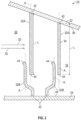
- FIG. 2 is an enlarged view of the labyrinth barrier 20.
- the labyrinth barrier 20 includes four members 32 arranged in a staggered pattern along two opposing surfaces 38, 40. Specifically, two members 32A are attached to an upper surface 38 of the upper wall 22 and two remaining members 32B are attached to a lower surface 40 of the lower wall 24, where alternating members 32 of the labyrinth barrier 20 are attached to the same surface 38, 40. Accordingly, the members 33 are arranged to create a flow pathway 30 having a winding configuration that restricts the flow between the two adjacent compartments 16, 26.
- Each member 32 includes a proximate end 42 and a distal end 44, where the members 32 are attached to either the upper surface 38 or the lower surface 40 at their respective proximate ends 42.
- one or more of the members 32 of the labyrinth barrier 20 are constructed entirely from the shape memory material 34.
- the members 32 are each constructed entirely from the shape memory material 34.
- a portion of the members 32 are constructed from the shape memory material 34, and a remaining portion of the members 32 are constructed from another material such as, for example, steel, titanium, copper nickel alloys, or composite materials.
- the shape memory material 34 includes shape memory alloy, a shape memory ceramic, and a shape memory polymer.
- Some examples of shape memory alloys include, but are not limited to, nickel titanium alloys or nickel copper aluminum alloys.
- shape memory polymers include, but are not limited to, polytetrafluoroethylene (PFTE), polylactide (PLA), and ethylene-vinyl acetate (EVA).
- PFTE polytetrafluoroethylene
- PLA polylactide
- EVA ethylene-vinyl acetate
- the shape memory material 34 includes the first energy state and the second energy state.
- the first energy state is either a low energy state or a high energy state.
- the low energy state may be referred to as the martensitic state and the high energy state may be referred to as the austenitic state for a shape memory alloy.
- the members 32 of the labyrinth barrier 20 are urged towards one another to restrict the flow pathway 30 when the shape memory material 34 transitions from a first energy state to a second energy state.
- the first energy state may be either the high energy state or the low energy state, depending upon the specific application.
- the members 32 each define a respective vertical axes A that extend along a length L the respective member 32.
- the members 32 are illustrated in FIG.2 in an original state, before the shape memory material 34 transitions from the first energy state to the second energy state.
- the labyrinth barrier 20 is part of the thrust reverser 10 shown in FIG. 1 , then the member 32 are in the original state before the engines (not shown) of the aircraft 12 are operating and produce the heat.
- the members 32 are oriented relative to one another by their respective vertical axes A in the original state to create the flow pathway 30.
- a fluid 52 that originates from the engine core compartment 26 that flows towards the thrust reverser compartment 16 is oriented in a direction transverse to the respective vertical axes A of the members 32.
- the members 32 are each oriented parallel to one another with respect to their vertical axes A when in the original state.
- the members 32 may also be oriented in other arrangements as well.
- FIG. 3 is an enlarged view of two adjacent members 32 of the labyrinth barrier 20, where the original state is shown in solid lines and a position of the members 32 after the shape memory material 34 has transitioned from the first energy state to the second energy state is shown in phantom line.
- the phantom lines illustrate the members 32 being urged towards one another to restrict the flow pathway 30 when the shape memory material 34 transitions from the first energy state to the second energy state.
- the members 32 are oriented parallel to one another with respect to their vertical axes A after the shape memory material 34 transitions from the first energy state to the second energy state as well.
- the members 32 are urged towards one another when the shape memory material 34 transitions from the low energy state to the high energy state. Alternatively, in another example, the members 32 are urged towards one another when the shape memory material 34 transitions from the high energy state to the low energy state.
- the shape memory material 34 transitions from the first energy state to the second energy state at an activation temperature.
- the members 32 are heated to the activation temperature of the shape memory material 34, where the shape memory material 34 transitions from the low energy state to the high energy state.
- the shape memory material 34 when the shape memory material 34 is heated, this does not necessarily require subjecting the shape memory material 34 to temperatures that are above normal room temperature, which ranges from about twenty to twenty-two degrees Celsius (68-72°F).
- the activation temperature of some types of shape memory materials may be at or below room temperature.
- the members 32 are cooled or reduced in temperature to the activation temperature, where the shape memory material 34 transitions from the high energy state to the low energy state.
- the shape memory material 34 when the shape memory material 34 is cooled, this does not necessarily require subjecting the shape memory material 34 to temperatures that are less than normal room temperature. It is to be appreciated that the members 32 return to the original state when the shape memory material 34 transitions from the second energy state back to the first energy state.
- the clearance C is defined as a required distance between two members 32 that are adjacent to one another when in the original state.
- the clearance C is sized to ensure the members 32 do not contact one another during fabrication and installation, or during the life of the labyrinth barrier 20 because of environmental concerns such as, but not limited to, thermal expansion or vibration.
- the clearance C is selected based on factors such as, but not limited to, an amount of flow restriction required in the original state, manufacturing tolerances, installation tolerances, vibrations experienced in the immediate vicinity of the labyrinth barrier 20, and thermal expansion. For example, installation tolerances allow for the thrust reverser 10 ( FIG. 1 ) to be opened and closed without having the members 32 contact one another. It is to be appreciated that the clearance C may be greater than the usual clearance that exists between adjacent members in a conventional labyrinth barrier, which is advantageous as this allows for more room during manufacturing and installation.
- the shape memory material 34 is in the low energy state when the members 32 are in the original position
- the labyrinth barrier 20 is an anti-fire barrier
- the shape memory material 34 is in the low energy state when the members 32 are in the original position.
- the members 32 are heated to the activation temperature of the shape memory material 34.
- the activation temperature is indicative of a flame present in an area adjacent to the labyrinth barrier 20.
- the adjacent area is the engine core compartment 26. Therefore, the members 32 are urged towards and contact one another, and the clearance C between two adjacent members 32 is eliminated. As a result, the flow pathway 30 is blocked.
- the labyrinth barrier 20 is not an anti-fire barrier
- the members 32 do not contact one another, and the clearance C is reduced but not eliminated.
- FIGS. 4A and 4B are a perspective view of another example of one of the members 132 of the labyrinth barrier 20.
- the member 132 defines a respective cross-sectional profile 150.
- the cross-sectional profile 150 includes two legs 152A, 152B.
- One of the legs 152A of the member 132 is attached to a structure, such as the upper wall 22 or the lower wall 24 of the thrust reverser 10 shown in FIG. 1 .
- One or more shape memory segments 154 constructed of the shape memory material 34 extends along the respective cross-sectional profile 150 of the member 132.
- the shape memory segments 154 are wires, ribbons, or sheets of the shape memory material 34. In the example as shown in FIG.S 4A and 4B , the shape memory segments 154 are embedded within the member 132. In one example, the shape memory segments 154 are attached to the member 132. The shape memory segments 154 may be attached to the member 132 using a variety of approaches. For example, the shape memory segments 154 may be mechanically fastened, bonded to, or embedded within the member 132.
- FIG. 4A illustrates the member 132 in the original state, where the legs 152A, 152B are oriented at an angle a relative to one another.
- the angle a is ninety degrees, and the members 32 are perpendicular to one another.
- FIG. 4A illustrates the legs 152A, 152B oriented perpendicular to one another, it is to be appreciated that FIG. 4A is merely exemplary in nature, and the legs 152A, 152B may be oriented relative to one another in a variety of configurations.
- the shape memory material 34 transitions from the first energy state to the second energy state, and the leg 152B is actuated either towards or away from the other leg 152A.
- the leg 152B is urged towards the remaining leg 152A, thereby reducing the angle a.
- FIGS. 5A and 5B illustrate yet another example of the labyrinth barrier 20, where at least one of the members 232 include a shape memory torque tube 260 constructed of the shape memory material 34. Specifically, in the example as shown, the shape memory torque tube 260 is located at the distal end 44 of the respective member 232.
- FIG. 5A illustrates the members 232 in the original state. Once the shape memory material 34 reaches the transition temperature, the shape memory torque tube 260 transmits a torsional force T ( FIG. 5B ), thereby actuating the members 232 towards one another, which is shown in FIG. 5B .
- the members 332 are constructed from a material other than the shape memory material 34. Instead, the members 332 are actuated or urged towards one another using a respective arm 360 constructed of the shape memory material 34.
- two adjacent members 332 are disposed along two opposing walls 22, 24.
- the members 332 each include a proximate end 342 and a distal end 344, where the proximate end 342 of the member 332 is attached a respective wall 322, 324.
- the arms 360 also include a respective proximate end 362 and a respective distal end 364, where a distal end 364 of a corresponding arm 360 is attached to the distal end 344 of the member 332.
- the arms 360 are each fixedly attached to a respective wall 22, 24 at the proximate end 362.
- each arm 360 corresponds to a member 332.
- the arm 360 is constructed at least in part of the shape memory material 34, where the arm 360 is fixedly attached to a corresponding member 332.
- the arm actuates as the shape memory material 34 transitions from the first energy state to the second energy state to urge the distal end 344 of the corresponding member 332 towards the distal end 344 of an adjacent member 332 to further restrict the flow pathway 30 (seen in FIG. 1 ) when the shape memory material transitions from the first energy state to the second energy state.
- FIG. 7 is an exemplary process flow diagram of a method 400 for actuating the labyrinth barrier 20.
- the method 400 begins at block 402.
- the flow pathway 30 ( FIG. 1 ) is created by two or more members 32 each defining a respective vertical axis, where one or more of the members 32 are constructed at least in part of the shape memory material 34.
- the method 400 may then proceed to block 404.
- the flow pathway 30 ( FIG. 1 ) restricts fluid flow in a direction transverse to the respective vertical axes A of the members 32.
- the members 32 are in the original state. The method 400 may then proceed to block 406.
- the shape memory material 34 of one or more of the members 32 is brought to the transition temperature.
- the shape memory material 34 may be heated or, alternatively, cooled to the transition temperature.
- the method 400 may then proceed to block 408.
- the members 32 are urged towards one another to further restrict the flow pathway 30 as the shape memory material transitions from the first energy state to the second energy state.
- the method 400 may then proceed to block 410.
- block 410 is optional and is used when the labyrinth barrier 20 is an anti-fire barrier.
- the members 32 are urged towards one another to block the flow pathway 30, which is shown in FIG. 3 .
- the method 400 may then terminate.
- the disclosed labyrinth barrier provides various technical effects and benefits. Specifically, a clearance exists between the members of the labyrinth barrier, and the clearance is sized as to ensure the members do not contact one another during fabrication and installation, or during the life of the labyrinth barrier 20 because of thermal expansion or vibration.
- the members of the labyrinth barrier are urged towards one another to further restrict flow.
- the members of the disclosed labyrinth barrier are dimensioned to avoid contact issues between the members in the original state, but the shape memory material allows for the members to still be able to block fluid flow when required. Therefore, the disclosed labyrinth barrier overcomes some of the issues faced by conventional barriers by providing sufficient clearance during fabrication, installation, or during operation, while also restricting or blocking the flow of fluid as the shape memory material transitions between phases as well.
Landscapes
- Engineering & Computer Science (AREA)
- Chemical & Material Sciences (AREA)
- Combustion & Propulsion (AREA)
- General Engineering & Computer Science (AREA)
- Mechanical Engineering (AREA)
- Materials Engineering (AREA)
- Sealing Using Fluids, Sealing Without Contact, And Removal Of Oil (AREA)
Claims (15)
- System, umfassend eine Labyrinthbarriere (20) und zwei gegenüberliegende Wände, wobei das System Folgendes umfasst:
zwei oder mehr Elemente (32), die jeweils vertikale Achsen definieren, wobei die Elemente (32) zumindest teilweise aus einem Formgedächtnismaterial (34) mit einem ersten Energiezustand und einem zweiten Energiezustand hergestellt sind und die Elemente (32) in einem Ausgangszustand relativ zueinander durch ihre jeweiligen vertikalen Achsen ausgerichtet sind, um einen Strömungsweg (30) zu erzeugen, der den Fluidstrom in einer Richtung quer zu den jeweiligen vertikalen Achsen einschränkt, wobei zwei benachbarte Elemente entlang der zwei gegenüberliegenden Wände angeordnet sind, wobei die benachbarten Elemente (32) aufeinander zu gedrängt werden, um den Strömungsweg (30) weiter einzuschränken, wenn das Formgedächtnismaterial (34) aus dem ersten Energiezustand in den zweiten Energiezustand übergeht. - System nach Anspruch 1, wobei das Formgedächtnismaterial (34) einen niedrigen Energiezustand und einen hohen Energiezustand umfasst.
- System nach Anspruch 2, wobei die benachbarten Elemente (32) aufeinander zu gedrängt werden, wenn das Formgedächtnismaterial (34) aus dem niedrigen Energiezustand in den hohen Energiezustand übergeht.
- System nach Anspruch 2, wobei die benachbarten Elemente (32) aufeinander zu gedrängt werden, wenn das Formgedächtnismaterial (34) aus dem hohen Energiezustand in den niedrigen Energiezustand übergeht.
- System nach einem der Ansprüche 1-4, wobei die benachbarten Elemente (32) einander berühren, um den Strömungsweg (30) zu blockieren, wenn das Formgedächtnismaterial (34) aus dem ersten Energiezustand in den zweiten Energiezustand übergeht.
- System nach einem der Ansprüche 1-5, wobei die Elemente (32) im Ausgangszustand parallel zueinander ausgerichtet sind.
- System nach einem der Ansprüche 1-6, wobei die Elemente (32) jeweils ein Querschnittsprofil (150) definieren.
- System nach Anspruch 7, wobei sich ein oder mehrere Formgedächtnissegmente (154) entlang des jeweiligen Querschnittsprofils (150) eines oder mehrerer der Elemente (32) erstrecken.
- System nach Anspruch 8, wobei das eine oder die mehreren Formgedächtnissegmente (154) an mindestens einem der Elemente (32) befestigt sind.
- System nach einem der Ansprüche 1-9, wobei das oder mindestens eines der Elemente (32) ein Formgedächtnistorsionsrohr (260) umfasst, das an einem nahe gelegenen Ende (42) angeordnet ist.
- System nach einem der Ansprüche 1-10, wobei das Formgedächtnismaterial (34) bei einer Aktivierungstemperatur aus einem oder dem niedrigen Energiezustand in einen oder den hohen Energiezustand übergeht.
- System nach Anspruch 11, wobei die Aktivierungstemperatur auf eine Flamme in einem an die Labyrinthbarriere (20) angrenzenden Bereich hinweist.
- Verfahren (400) zum Begrenzen des Stroms durch eine Labyrinthbarriere (20), wobei das Verfahren (400) Folgendes umfasst:Erzeugen eines Strömungswegs (30) durch zwei oder mehr Elemente (32) der Labyrinthbarriere (20), wobei jedes Element (32) eine vertikale Achse definiert und die Elemente (32) zumindest teilweise aus einem Formgedächtnismaterial (34) mit einem ersten Energiezustand und einem zweiten Energiezustand hergestellt sind;Einschränken des Fluidstroms in einer Richtung quer zu den jeweiligen vertikalen Achsen der Elemente (32);Bringen des Formgedächtnismaterials (34) von zwei benachbarten Elementen, die entlang zwei gegenüberliegender Wände angeordnet sind, auf eine Übergangstemperatur des Formgedächtnismaterials (34); undDrängen der benachbarten Elemente (32) aufeinander zu, um den Strömungsweg (30) weiter einzuschränken, wenn das Formgedächtnismaterial (34) aus dem ersten Energiezustand in den zweiten Energiezustand übergeht.
- Verfahren (400) nach Anspruch 13, ferner umfassend: Drängen der benachbarten Elemente (32) aufeinander zu, um den Strömungsweg (30) zu blockieren.
- Verfahren (400) nach Anspruch 13 oder 14, wobei das Formgedächtnismaterial (34) mindestens eines von einer Formgedächtnislegierung, einer Formgedächtniskeramik und einem Formgedächtnispolymer ist.
Applications Claiming Priority (2)
| Application Number | Priority Date | Filing Date | Title |
|---|---|---|---|
| US202063052178P | 2020-07-15 | 2020-07-15 | |
| US17/370,238 US11592112B2 (en) | 2020-07-15 | 2021-07-08 | Labyrinth barrier with members constructed of a shape memory material |
Publications (2)
| Publication Number | Publication Date |
|---|---|
| EP3940202A1 EP3940202A1 (de) | 2022-01-19 |
| EP3940202B1 true EP3940202B1 (de) | 2024-12-25 |
Family
ID=78828862
Family Applications (1)
| Application Number | Title | Priority Date | Filing Date |
|---|---|---|---|
| EP21185337.9A Active EP3940202B1 (de) | 2020-07-15 | 2021-07-13 | Labyrinthbarriere mit elementen aus einem formgedächtnismaterial |
Country Status (2)
| Country | Link |
|---|---|
| US (1) | US11592112B2 (de) |
| EP (1) | EP3940202B1 (de) |
Citations (2)
| Publication number | Priority date | Publication date | Assignee | Title |
|---|---|---|---|---|
| JPH01146070U (de) * | 1988-03-31 | 1989-10-06 | ||
| JPH0438140A (ja) * | 1990-05-31 | 1992-02-07 | Fuji Electric Co Ltd | ラビリンスシール装置 |
Family Cites Families (27)
| Publication number | Priority date | Publication date | Assignee | Title |
|---|---|---|---|---|
| US5181341A (en) | 1990-05-14 | 1993-01-26 | The Standard Products Company | Variable gap filling system |
| GB2273733B (en) | 1992-12-22 | 1996-05-01 | Draftex Ind Ltd | Sealing methods and arrangements |
| US5390974A (en) | 1993-12-27 | 1995-02-21 | Ford Motor Company | Variable hardness weatherstrip |
| FR2738046B1 (fr) * | 1995-08-23 | 1997-09-19 | Snecma | Joint d'etancheite a labyrinthe |
| US6683965B1 (en) | 1995-10-20 | 2004-01-27 | Bose Corporation | In-the-ear noise reduction headphones |
| US5910094A (en) | 1996-09-10 | 1999-06-08 | The Boeing Company | Aircraft labyrinth fire seal |
| US5899463A (en) | 1996-10-25 | 1999-05-04 | The Boeing Company | Pressure augmented kiss seal |
| US5940788A (en) | 1997-05-02 | 1999-08-17 | Ford Global Technologies, Inc. | Method and system for designing vehicle door seals based on predicted sound transmission characteristics |
| DE19826170C1 (de) | 1998-06-13 | 1999-10-14 | Daimler Chrysler Ag | Verfahren und Vorrichtung zur aktiven Beeinflussung einer Geräuschkulisse einer rotierende Teile aufweisenden Maschine |
| JP3621662B2 (ja) | 2001-07-02 | 2005-02-16 | 西川ゴム工業株式会社 | 自動車用ウェザーストリップ |
| US7594359B2 (en) | 2004-03-12 | 2009-09-29 | Gm Global Technology Operations, Inc. | Active seal assemblies for sound isolation |
| US20050198904A1 (en) | 2004-03-12 | 2005-09-15 | Browne Alan L. | Active seal assemblies for movable windows |
| US7484735B2 (en) | 2004-12-09 | 2009-02-03 | General Motors Corporation | Reversible thermally expandable and/or contractible seal assemblies |
| US20120286480A1 (en) | 2006-04-18 | 2012-11-15 | Anatoly Ivanovich Efremov | Negative creep corrugated gasket and methods of manufacturing same |
| EP1914388A1 (de) * | 2006-10-20 | 2008-04-23 | Siemens Aktiengesellschaft | Dichtelement zur Abdichtung eines Leckagespalts zwischen einem Rotor und einem Stator einer thermischen Strömungsmaschine. |
| EP2000709B1 (de) | 2007-06-04 | 2009-08-12 | C.R.F. Società Consortile per Azioni | Dichtring |
| US20150083281A1 (en) | 2007-12-26 | 2015-03-26 | General Electric Company | High temperature shape memory alloy actuators |
| CN102056759B (zh) * | 2008-04-10 | 2015-01-14 | 通用汽车环球科技运作公司 | 活性密封架构 |
| US20130134679A1 (en) * | 2011-11-30 | 2013-05-30 | General Electric Company | Non-contacting seal arrangement, electromechanical system having a non-contacting seal arrangement, and method of fabricating a non-contacting seal arrangement |
| WO2014137444A2 (en) * | 2012-12-29 | 2014-09-12 | United Technologies Corporation | Multi-ply finger seal |
| WO2014133615A1 (en) * | 2013-03-01 | 2014-09-04 | Rolls-Royce Corporation | Bi-metal strip-seal |
| US9567113B2 (en) * | 2013-05-03 | 2017-02-14 | The Boeing Company | Thermal seal with thermally induced shape change |
| US9863536B2 (en) | 2015-12-30 | 2018-01-09 | Onesubsea Ip Uk Limited | Multi-material seal having a seal body and core |
| EP3464961B1 (de) | 2016-06-03 | 2020-05-13 | FMC Technologies, Inc. | Element aus einer formgedächtnislegierung zur verwendung in polymer- oder verbunddichtungsanwendungen |
| JP6830804B2 (ja) * | 2016-12-05 | 2021-02-17 | 三菱航空機株式会社 | 航空機用のファイアシール構造および航空機 |
| US10995859B2 (en) | 2018-04-26 | 2021-05-04 | Honda Motor Co., Ltd. | Thermally actuated grommet |
| US11293552B2 (en) * | 2020-01-03 | 2022-04-05 | Raytheon Technologies Corporation | Brush seal with shape memory alloy |
-
2021
- 2021-07-08 US US17/370,238 patent/US11592112B2/en active Active
- 2021-07-13 EP EP21185337.9A patent/EP3940202B1/de active Active
Patent Citations (2)
| Publication number | Priority date | Publication date | Assignee | Title |
|---|---|---|---|---|
| JPH01146070U (de) * | 1988-03-31 | 1989-10-06 | ||
| JPH0438140A (ja) * | 1990-05-31 | 1992-02-07 | Fuji Electric Co Ltd | ラビリンスシール装置 |
Also Published As
| Publication number | Publication date |
|---|---|
| EP3940202A1 (de) | 2022-01-19 |
| US11592112B2 (en) | 2023-02-28 |
| US20220018444A1 (en) | 2022-01-20 |
Similar Documents
| Publication | Publication Date | Title |
|---|---|---|
| KR100871194B1 (ko) | 회전 기계용 인서트 조립체, 터빈 및 터빈의 인서트 조립체개장 방법 | |
| US7367776B2 (en) | Turbine engine stator including shape memory alloy and clearance control method | |
| EP3097273B1 (de) | Halteklammer für eine aussendichtung einer turbinenschaufel | |
| EP3348792B1 (de) | Dichtungsanordnung für gasturbinenmotorkomponenten | |
| US7901186B2 (en) | Seal assembly | |
| EP3155230B1 (de) | Mehrteilige ummantelungsaufhängungsanordnung | |
| EP2964896B1 (de) | System und verfahren zur leckagevermeidung in einer turbine | |
| EP3269940A1 (de) | Verdichter und zugehöriger gasturbinenmotor mit einem solchen verdichter | |
| EP2910822A1 (de) | Maschinenhohlraumabdichtung | |
| JP2009150382A (ja) | 断熱型フランジボルト | |
| EP3845783B1 (de) | Bürstendichtung mit formgedächtnislegierung | |
| US20170218768A1 (en) | Blade of a turbomachine having blade root thermal insulation | |
| EP2956635B1 (de) | Hitzeschildverteilersystem für ein mittelrahmengehäuse eines gasturbinenmotors | |
| EP2530251A2 (de) | Scharnierdichtung | |
| BR112015006099B1 (pt) | Mancal de impulso, turbomáquina e método para fazer um disco de rotor | |
| EP2530252A2 (de) | Flexible Dichtung | |
| CA3118681A1 (en) | Labyrinth barrier with members constructed of a shape memory material | |
| US11592112B2 (en) | Labyrinth barrier with members constructed of a shape memory material | |
| EP3047130B1 (de) | Gas turbinen dichtungsanordnung welche wabendichtungen mit keilprofil beinhaltet | |
| US11125095B2 (en) | Sliding seal | |
| CN214118340U (zh) | 航空发动机及其封严组件 | |
| EP2743449A2 (de) | Drehbarer Wärmeschild einer Laufradhinterseite | |
| US8544852B2 (en) | Torsion seal | |
| US20150275682A1 (en) | Sprayed haynes 230 layer to increase spallation life of thermal barrier coating on a gas turbine engine component |
Legal Events
| Date | Code | Title | Description |
|---|---|---|---|
| PUAI | Public reference made under article 153(3) epc to a published international application that has entered the european phase |
Free format text: ORIGINAL CODE: 0009012 |
|
| STAA | Information on the status of an ep patent application or granted ep patent |
Free format text: STATUS: THE APPLICATION HAS BEEN PUBLISHED |
|
| AK | Designated contracting states |
Kind code of ref document: A1 Designated state(s): AL AT BE BG CH CY CZ DE DK EE ES FI FR GB GR HR HU IE IS IT LI LT LU LV MC MK MT NL NO PL PT RO RS SE SI SK SM TR |
|
| STAA | Information on the status of an ep patent application or granted ep patent |
Free format text: STATUS: REQUEST FOR EXAMINATION WAS MADE |
|
| 17P | Request for examination filed |
Effective date: 20220630 |
|
| RBV | Designated contracting states (corrected) |
Designated state(s): AL AT BE BG CH CY CZ DE DK EE ES FI FR GB GR HR HU IE IS IT LI LT LU LV MC MK MT NL NO PL PT RO RS SE SI SK SM TR |
|
| RAP3 | Party data changed (applicant data changed or rights of an application transferred) |
Owner name: THE BOEING COMPANY |
|
| STAA | Information on the status of an ep patent application or granted ep patent |
Free format text: STATUS: EXAMINATION IS IN PROGRESS |
|
| 17Q | First examination report despatched |
Effective date: 20231123 |
|
| GRAP | Despatch of communication of intention to grant a patent |
Free format text: ORIGINAL CODE: EPIDOSNIGR1 |
|
| STAA | Information on the status of an ep patent application or granted ep patent |
Free format text: STATUS: GRANT OF PATENT IS INTENDED |
|
| RIC1 | Information provided on ipc code assigned before grant |
Ipc: F01D 25/00 20060101ALI20240710BHEP Ipc: F02C 7/25 20060101ALI20240710BHEP Ipc: F02C 7/28 20060101ALI20240710BHEP Ipc: F02K 1/80 20060101ALI20240710BHEP Ipc: F01D 11/02 20060101AFI20240710BHEP |
|
| INTG | Intention to grant announced |
Effective date: 20240801 |
|
| GRAS | Grant fee paid |
Free format text: ORIGINAL CODE: EPIDOSNIGR3 |
|
| GRAA | (expected) grant |
Free format text: ORIGINAL CODE: 0009210 |
|
| STAA | Information on the status of an ep patent application or granted ep patent |
Free format text: STATUS: THE PATENT HAS BEEN GRANTED |
|
| AK | Designated contracting states |
Kind code of ref document: B1 Designated state(s): AL AT BE BG CH CY CZ DE DK EE ES FI FR GB GR HR HU IE IS IT LI LT LU LV MC MK MT NL NO PL PT RO RS SE SI SK SM TR |
|
| P01 | Opt-out of the competence of the unified patent court (upc) registered |
Free format text: CASE NUMBER: APP_61274/2024 Effective date: 20241115 |
|
| REG | Reference to a national code |
Ref country code: GB Ref legal event code: FG4D |
|
| REG | Reference to a national code |
Ref country code: CH Ref legal event code: EP |
|
| REG | Reference to a national code |
Ref country code: DE Ref legal event code: R096 Ref document number: 602021023799 Country of ref document: DE |
|
| REG | Reference to a national code |
Ref country code: IE Ref legal event code: FG4D |
|
| REG | Reference to a national code |
Ref country code: LT Ref legal event code: MG9D |
|
| PG25 | Lapsed in a contracting state [announced via postgrant information from national office to epo] |
Ref country code: HR Free format text: LAPSE BECAUSE OF FAILURE TO SUBMIT A TRANSLATION OF THE DESCRIPTION OR TO PAY THE FEE WITHIN THE PRESCRIBED TIME-LIMIT Effective date: 20241225 |
|
| PG25 | Lapsed in a contracting state [announced via postgrant information from national office to epo] |
Ref country code: FI Free format text: LAPSE BECAUSE OF FAILURE TO SUBMIT A TRANSLATION OF THE DESCRIPTION OR TO PAY THE FEE WITHIN THE PRESCRIBED TIME-LIMIT Effective date: 20241225 |
|
| PG25 | Lapsed in a contracting state [announced via postgrant information from national office to epo] |
Ref country code: BG Free format text: LAPSE BECAUSE OF FAILURE TO SUBMIT A TRANSLATION OF THE DESCRIPTION OR TO PAY THE FEE WITHIN THE PRESCRIBED TIME-LIMIT Effective date: 20241225 |
|
| PG25 | Lapsed in a contracting state [announced via postgrant information from national office to epo] |
Ref country code: NO Free format text: LAPSE BECAUSE OF FAILURE TO SUBMIT A TRANSLATION OF THE DESCRIPTION OR TO PAY THE FEE WITHIN THE PRESCRIBED TIME-LIMIT Effective date: 20250325 |
|
| PG25 | Lapsed in a contracting state [announced via postgrant information from national office to epo] |
Ref country code: GR Free format text: LAPSE BECAUSE OF FAILURE TO SUBMIT A TRANSLATION OF THE DESCRIPTION OR TO PAY THE FEE WITHIN THE PRESCRIBED TIME-LIMIT Effective date: 20250326 Ref country code: LV Free format text: LAPSE BECAUSE OF FAILURE TO SUBMIT A TRANSLATION OF THE DESCRIPTION OR TO PAY THE FEE WITHIN THE PRESCRIBED TIME-LIMIT Effective date: 20241225 |
|
| PG25 | Lapsed in a contracting state [announced via postgrant information from national office to epo] |
Ref country code: RS Free format text: LAPSE BECAUSE OF FAILURE TO SUBMIT A TRANSLATION OF THE DESCRIPTION OR TO PAY THE FEE WITHIN THE PRESCRIBED TIME-LIMIT Effective date: 20250325 |
|
| REG | Reference to a national code |
Ref country code: NL Ref legal event code: MP Effective date: 20241225 |
|
| PG25 | Lapsed in a contracting state [announced via postgrant information from national office to epo] |
Ref country code: NL Free format text: LAPSE BECAUSE OF FAILURE TO SUBMIT A TRANSLATION OF THE DESCRIPTION OR TO PAY THE FEE WITHIN THE PRESCRIBED TIME-LIMIT Effective date: 20241225 |
|
| REG | Reference to a national code |
Ref country code: AT Ref legal event code: MK05 Ref document number: 1754320 Country of ref document: AT Kind code of ref document: T Effective date: 20241225 |
|
| PG25 | Lapsed in a contracting state [announced via postgrant information from national office to epo] |
Ref country code: SM Free format text: LAPSE BECAUSE OF FAILURE TO SUBMIT A TRANSLATION OF THE DESCRIPTION OR TO PAY THE FEE WITHIN THE PRESCRIBED TIME-LIMIT Effective date: 20241225 |
|
| PG25 | Lapsed in a contracting state [announced via postgrant information from national office to epo] |
Ref country code: PL Free format text: LAPSE BECAUSE OF FAILURE TO SUBMIT A TRANSLATION OF THE DESCRIPTION OR TO PAY THE FEE WITHIN THE PRESCRIBED TIME-LIMIT Effective date: 20241225 |
|
| PG25 | Lapsed in a contracting state [announced via postgrant information from national office to epo] |
Ref country code: ES Free format text: LAPSE BECAUSE OF FAILURE TO SUBMIT A TRANSLATION OF THE DESCRIPTION OR TO PAY THE FEE WITHIN THE PRESCRIBED TIME-LIMIT Effective date: 20241225 |
|
| PG25 | Lapsed in a contracting state [announced via postgrant information from national office to epo] |
Ref country code: IS Free format text: LAPSE BECAUSE OF FAILURE TO SUBMIT A TRANSLATION OF THE DESCRIPTION OR TO PAY THE FEE WITHIN THE PRESCRIBED TIME-LIMIT Effective date: 20250425 |
|
| PG25 | Lapsed in a contracting state [announced via postgrant information from national office to epo] |
Ref country code: PT Free format text: LAPSE BECAUSE OF FAILURE TO SUBMIT A TRANSLATION OF THE DESCRIPTION OR TO PAY THE FEE WITHIN THE PRESCRIBED TIME-LIMIT Effective date: 20250428 |
|
| PG25 | Lapsed in a contracting state [announced via postgrant information from national office to epo] |
Ref country code: EE Free format text: LAPSE BECAUSE OF FAILURE TO SUBMIT A TRANSLATION OF THE DESCRIPTION OR TO PAY THE FEE WITHIN THE PRESCRIBED TIME-LIMIT Effective date: 20241225 |
|
| PG25 | Lapsed in a contracting state [announced via postgrant information from national office to epo] |
Ref country code: RO Free format text: LAPSE BECAUSE OF FAILURE TO SUBMIT A TRANSLATION OF THE DESCRIPTION OR TO PAY THE FEE WITHIN THE PRESCRIBED TIME-LIMIT Effective date: 20241225 Ref country code: AT Free format text: LAPSE BECAUSE OF FAILURE TO SUBMIT A TRANSLATION OF THE DESCRIPTION OR TO PAY THE FEE WITHIN THE PRESCRIBED TIME-LIMIT Effective date: 20241225 |
|
| PG25 | Lapsed in a contracting state [announced via postgrant information from national office to epo] |
Ref country code: SK Free format text: LAPSE BECAUSE OF FAILURE TO SUBMIT A TRANSLATION OF THE DESCRIPTION OR TO PAY THE FEE WITHIN THE PRESCRIBED TIME-LIMIT Effective date: 20241225 |
|
| PG25 | Lapsed in a contracting state [announced via postgrant information from national office to epo] |
Ref country code: CZ Free format text: LAPSE BECAUSE OF FAILURE TO SUBMIT A TRANSLATION OF THE DESCRIPTION OR TO PAY THE FEE WITHIN THE PRESCRIBED TIME-LIMIT Effective date: 20241225 |
|
| PG25 | Lapsed in a contracting state [announced via postgrant information from national office to epo] |
Ref country code: IT Free format text: LAPSE BECAUSE OF FAILURE TO SUBMIT A TRANSLATION OF THE DESCRIPTION OR TO PAY THE FEE WITHIN THE PRESCRIBED TIME-LIMIT Effective date: 20241225 |
|
| PG25 | Lapsed in a contracting state [announced via postgrant information from national office to epo] |
Ref country code: SE Free format text: LAPSE BECAUSE OF FAILURE TO SUBMIT A TRANSLATION OF THE DESCRIPTION OR TO PAY THE FEE WITHIN THE PRESCRIBED TIME-LIMIT Effective date: 20241225 |
|
| REG | Reference to a national code |
Ref country code: DE Ref legal event code: R097 Ref document number: 602021023799 Country of ref document: DE |
|
| PG25 | Lapsed in a contracting state [announced via postgrant information from national office to epo] |
Ref country code: DK Free format text: LAPSE BECAUSE OF FAILURE TO SUBMIT A TRANSLATION OF THE DESCRIPTION OR TO PAY THE FEE WITHIN THE PRESCRIBED TIME-LIMIT Effective date: 20241225 |
|
| PGFP | Annual fee paid to national office [announced via postgrant information from national office to epo] |
Ref country code: DE Payment date: 20250729 Year of fee payment: 5 |
|
| PGFP | Annual fee paid to national office [announced via postgrant information from national office to epo] |
Ref country code: GB Payment date: 20250728 Year of fee payment: 5 |
|
| PGFP | Annual fee paid to national office [announced via postgrant information from national office to epo] |
Ref country code: FR Payment date: 20250725 Year of fee payment: 5 |
|
| PLBE | No opposition filed within time limit |
Free format text: ORIGINAL CODE: 0009261 |
|
| STAA | Information on the status of an ep patent application or granted ep patent |
Free format text: STATUS: NO OPPOSITION FILED WITHIN TIME LIMIT |
|
| REG | Reference to a national code |
Ref country code: CH Ref legal event code: L10 Free format text: ST27 STATUS EVENT CODE: U-0-0-L10-L00 (AS PROVIDED BY THE NATIONAL OFFICE) Effective date: 20251105 |
|
| 26N | No opposition filed |
Effective date: 20250926 |
|
| REG | Reference to a national code |
Ref country code: CH Ref legal event code: H13 Free format text: ST27 STATUS EVENT CODE: U-0-0-H10-H13 (AS PROVIDED BY THE NATIONAL OFFICE) Effective date: 20260224 |
|
| PG25 | Lapsed in a contracting state [announced via postgrant information from national office to epo] |
Ref country code: LU Free format text: LAPSE BECAUSE OF NON-PAYMENT OF DUE FEES Effective date: 20250713 |
|
| REG | Reference to a national code |
Ref country code: BE Ref legal event code: MM Effective date: 20250731 |
|
| PG25 | Lapsed in a contracting state [announced via postgrant information from national office to epo] |
Ref country code: BE Free format text: LAPSE BECAUSE OF NON-PAYMENT OF DUE FEES Effective date: 20250731 |
|
| PG25 | Lapsed in a contracting state [announced via postgrant information from national office to epo] |
Ref country code: CH Free format text: LAPSE BECAUSE OF NON-PAYMENT OF DUE FEES Effective date: 20250731 |