EP3940246A1 - Ventilanordnung und verfahren zur ansteuerung eines hubwerks oder anbaugeräts - Google Patents
Ventilanordnung und verfahren zur ansteuerung eines hubwerks oder anbaugeräts Download PDFInfo
- Publication number
- EP3940246A1 EP3940246A1 EP21185034.2A EP21185034A EP3940246A1 EP 3940246 A1 EP3940246 A1 EP 3940246A1 EP 21185034 A EP21185034 A EP 21185034A EP 3940246 A1 EP3940246 A1 EP 3940246A1
- Authority
- EP
- European Patent Office
- Prior art keywords
- pressure
- lowering
- valve
- directional control
- active
- Prior art date
- Legal status (The legal status is an assumption and is not a legal conclusion. Google has not performed a legal analysis and makes no representation as to the accuracy of the status listed.)
- Granted
Links
Images




Classifications
-
- F—MECHANICAL ENGINEERING; LIGHTING; HEATING; WEAPONS; BLASTING
- F15—FLUID-PRESSURE ACTUATORS; HYDRAULICS OR PNEUMATICS IN GENERAL
- F15B—SYSTEMS ACTING BY MEANS OF FLUIDS IN GENERAL; FLUID-PRESSURE ACTUATORS, e.g. SERVOMOTORS; DETAILS OF FLUID-PRESSURE SYSTEMS, NOT OTHERWISE PROVIDED FOR
- F15B13/00—Details of servomotor systems ; Valves for servomotor systems
- F15B13/02—Fluid distribution or supply devices characterised by their adaptation to the control of servomotors
- F15B13/04—Fluid distribution or supply devices characterised by their adaptation to the control of servomotors for use with a single servomotor
- F15B13/0401—Valve members; Fluid interconnections therefor
- F15B13/0402—Valve members; Fluid interconnections therefor for linearly sliding valves, e.g. spool valves
-
- F—MECHANICAL ENGINEERING; LIGHTING; HEATING; WEAPONS; BLASTING
- F15—FLUID-PRESSURE ACTUATORS; HYDRAULICS OR PNEUMATICS IN GENERAL
- F15B—SYSTEMS ACTING BY MEANS OF FLUIDS IN GENERAL; FLUID-PRESSURE ACTUATORS, e.g. SERVOMOTORS; DETAILS OF FLUID-PRESSURE SYSTEMS, NOT OTHERWISE PROVIDED FOR
- F15B11/00—Servomotor systems without provision for follow-up action; Circuits therefor
- F15B11/02—Systems essentially incorporating special features for controlling the speed or actuating force of an output member
- F15B11/04—Systems essentially incorporating special features for controlling the speed or actuating force of an output member for controlling the speed
- F15B11/05—Systems essentially incorporating special features for controlling the speed or actuating force of an output member for controlling the speed specially adapted to maintain constant speed, e.g. pressure-compensated, load-responsive
-
- F—MECHANICAL ENGINEERING; LIGHTING; HEATING; WEAPONS; BLASTING
- F15—FLUID-PRESSURE ACTUATORS; HYDRAULICS OR PNEUMATICS IN GENERAL
- F15B—SYSTEMS ACTING BY MEANS OF FLUIDS IN GENERAL; FLUID-PRESSURE ACTUATORS, e.g. SERVOMOTORS; DETAILS OF FLUID-PRESSURE SYSTEMS, NOT OTHERWISE PROVIDED FOR
- F15B11/00—Servomotor systems without provision for follow-up action; Circuits therefor
- F15B11/02—Systems essentially incorporating special features for controlling the speed or actuating force of an output member
- F15B11/024—Systems essentially incorporating special features for controlling the speed or actuating force of an output member by means of differential connection of the servomotor lines, e.g. regenerative circuits
-
- F—MECHANICAL ENGINEERING; LIGHTING; HEATING; WEAPONS; BLASTING
- F15—FLUID-PRESSURE ACTUATORS; HYDRAULICS OR PNEUMATICS IN GENERAL
- F15B—SYSTEMS ACTING BY MEANS OF FLUIDS IN GENERAL; FLUID-PRESSURE ACTUATORS, e.g. SERVOMOTORS; DETAILS OF FLUID-PRESSURE SYSTEMS, NOT OTHERWISE PROVIDED FOR
- F15B13/00—Details of servomotor systems ; Valves for servomotor systems
- F15B13/02—Fluid distribution or supply devices characterised by their adaptation to the control of servomotors
- F15B13/04—Fluid distribution or supply devices characterised by their adaptation to the control of servomotors for use with a single servomotor
- F15B13/0401—Valve members; Fluid interconnections therefor
- F15B2013/0413—Valve members; Fluid interconnections therefor with four or more positions
-
- F—MECHANICAL ENGINEERING; LIGHTING; HEATING; WEAPONS; BLASTING
- F15—FLUID-PRESSURE ACTUATORS; HYDRAULICS OR PNEUMATICS IN GENERAL
- F15B—SYSTEMS ACTING BY MEANS OF FLUIDS IN GENERAL; FLUID-PRESSURE ACTUATORS, e.g. SERVOMOTORS; DETAILS OF FLUID-PRESSURE SYSTEMS, NOT OTHERWISE PROVIDED FOR
- F15B2211/00—Circuits for servomotor systems
- F15B2211/20—Fluid pressure source, e.g. accumulator or variable axial piston pump
- F15B2211/205—Systems with pumps
- F15B2211/2053—Type of pump
- F15B2211/20546—Type of pump variable capacity
- F15B2211/20553—Type of pump variable capacity with pilot circuit, e.g. for controlling a swash plate
-
- F—MECHANICAL ENGINEERING; LIGHTING; HEATING; WEAPONS; BLASTING
- F15—FLUID-PRESSURE ACTUATORS; HYDRAULICS OR PNEUMATICS IN GENERAL
- F15B—SYSTEMS ACTING BY MEANS OF FLUIDS IN GENERAL; FLUID-PRESSURE ACTUATORS, e.g. SERVOMOTORS; DETAILS OF FLUID-PRESSURE SYSTEMS, NOT OTHERWISE PROVIDED FOR
- F15B2211/00—Circuits for servomotor systems
- F15B2211/30—Directional control
- F15B2211/305—Directional control characterised by the type of valves
- F15B2211/30505—Non-return valves, i.e. check valves
- F15B2211/30515—Load holding valves
-
- F—MECHANICAL ENGINEERING; LIGHTING; HEATING; WEAPONS; BLASTING
- F15—FLUID-PRESSURE ACTUATORS; HYDRAULICS OR PNEUMATICS IN GENERAL
- F15B—SYSTEMS ACTING BY MEANS OF FLUIDS IN GENERAL; FLUID-PRESSURE ACTUATORS, e.g. SERVOMOTORS; DETAILS OF FLUID-PRESSURE SYSTEMS, NOT OTHERWISE PROVIDED FOR
- F15B2211/00—Circuits for servomotor systems
- F15B2211/30—Directional control
- F15B2211/305—Directional control characterised by the type of valves
- F15B2211/30525—Directional control valves, e.g. 4/3-directional control valve
- F15B2211/3053—In combination with a pressure compensating valve
- F15B2211/30535—In combination with a pressure compensating valve the pressure compensating valve is arranged between pressure source and directional control valve
-
- F—MECHANICAL ENGINEERING; LIGHTING; HEATING; WEAPONS; BLASTING
- F15—FLUID-PRESSURE ACTUATORS; HYDRAULICS OR PNEUMATICS IN GENERAL
- F15B—SYSTEMS ACTING BY MEANS OF FLUIDS IN GENERAL; FLUID-PRESSURE ACTUATORS, e.g. SERVOMOTORS; DETAILS OF FLUID-PRESSURE SYSTEMS, NOT OTHERWISE PROVIDED FOR
- F15B2211/00—Circuits for servomotor systems
- F15B2211/30—Directional control
- F15B2211/31—Directional control characterised by the positions of the valve element
- F15B2211/3105—Neutral or centre positions
- F15B2211/3111—Neutral or centre positions the pump port being closed in the centre position, e.g. so-called closed centre
-
- F—MECHANICAL ENGINEERING; LIGHTING; HEATING; WEAPONS; BLASTING
- F15—FLUID-PRESSURE ACTUATORS; HYDRAULICS OR PNEUMATICS IN GENERAL
- F15B—SYSTEMS ACTING BY MEANS OF FLUIDS IN GENERAL; FLUID-PRESSURE ACTUATORS, e.g. SERVOMOTORS; DETAILS OF FLUID-PRESSURE SYSTEMS, NOT OTHERWISE PROVIDED FOR
- F15B2211/00—Circuits for servomotor systems
- F15B2211/30—Directional control
- F15B2211/31—Directional control characterised by the positions of the valve element
- F15B2211/3122—Special positions other than the pump port being connected to working ports or the working ports being connected to the return line
-
- F—MECHANICAL ENGINEERING; LIGHTING; HEATING; WEAPONS; BLASTING
- F15—FLUID-PRESSURE ACTUATORS; HYDRAULICS OR PNEUMATICS IN GENERAL
- F15B—SYSTEMS ACTING BY MEANS OF FLUIDS IN GENERAL; FLUID-PRESSURE ACTUATORS, e.g. SERVOMOTORS; DETAILS OF FLUID-PRESSURE SYSTEMS, NOT OTHERWISE PROVIDED FOR
- F15B2211/00—Circuits for servomotor systems
- F15B2211/30—Directional control
- F15B2211/31—Directional control characterised by the positions of the valve element
- F15B2211/3122—Special positions other than the pump port being connected to working ports or the working ports being connected to the return line
- F15B2211/3127—Floating position connecting the working ports and the return line
-
- F—MECHANICAL ENGINEERING; LIGHTING; HEATING; WEAPONS; BLASTING
- F15—FLUID-PRESSURE ACTUATORS; HYDRAULICS OR PNEUMATICS IN GENERAL
- F15B—SYSTEMS ACTING BY MEANS OF FLUIDS IN GENERAL; FLUID-PRESSURE ACTUATORS, e.g. SERVOMOTORS; DETAILS OF FLUID-PRESSURE SYSTEMS, NOT OTHERWISE PROVIDED FOR
- F15B2211/00—Circuits for servomotor systems
- F15B2211/30—Directional control
- F15B2211/31—Directional control characterised by the positions of the valve element
- F15B2211/3122—Special positions other than the pump port being connected to working ports or the working ports being connected to the return line
- F15B2211/3133—Regenerative position connecting the working ports or connecting the working ports to the pump, e.g. for high-speed approach stroke
-
- F—MECHANICAL ENGINEERING; LIGHTING; HEATING; WEAPONS; BLASTING
- F15—FLUID-PRESSURE ACTUATORS; HYDRAULICS OR PNEUMATICS IN GENERAL
- F15B—SYSTEMS ACTING BY MEANS OF FLUIDS IN GENERAL; FLUID-PRESSURE ACTUATORS, e.g. SERVOMOTORS; DETAILS OF FLUID-PRESSURE SYSTEMS, NOT OTHERWISE PROVIDED FOR
- F15B2211/00—Circuits for servomotor systems
- F15B2211/30—Directional control
- F15B2211/31—Directional control characterised by the positions of the valve element
- F15B2211/3144—Directional control characterised by the positions of the valve element the positions being continuously variable, e.g. as realised by proportional valves
-
- F—MECHANICAL ENGINEERING; LIGHTING; HEATING; WEAPONS; BLASTING
- F15—FLUID-PRESSURE ACTUATORS; HYDRAULICS OR PNEUMATICS IN GENERAL
- F15B—SYSTEMS ACTING BY MEANS OF FLUIDS IN GENERAL; FLUID-PRESSURE ACTUATORS, e.g. SERVOMOTORS; DETAILS OF FLUID-PRESSURE SYSTEMS, NOT OTHERWISE PROVIDED FOR
- F15B2211/00—Circuits for servomotor systems
- F15B2211/30—Directional control
- F15B2211/32—Directional control characterised by the type of actuation
- F15B2211/327—Directional control characterised by the type of actuation electrically or electronically
-
- F—MECHANICAL ENGINEERING; LIGHTING; HEATING; WEAPONS; BLASTING
- F15—FLUID-PRESSURE ACTUATORS; HYDRAULICS OR PNEUMATICS IN GENERAL
- F15B—SYSTEMS ACTING BY MEANS OF FLUIDS IN GENERAL; FLUID-PRESSURE ACTUATORS, e.g. SERVOMOTORS; DETAILS OF FLUID-PRESSURE SYSTEMS, NOT OTHERWISE PROVIDED FOR
- F15B2211/00—Circuits for servomotor systems
- F15B2211/30—Directional control
- F15B2211/32—Directional control characterised by the type of actuation
- F15B2211/329—Directional control characterised by the type of actuation actuated by fluid pressure
-
- F—MECHANICAL ENGINEERING; LIGHTING; HEATING; WEAPONS; BLASTING
- F15—FLUID-PRESSURE ACTUATORS; HYDRAULICS OR PNEUMATICS IN GENERAL
- F15B—SYSTEMS ACTING BY MEANS OF FLUIDS IN GENERAL; FLUID-PRESSURE ACTUATORS, e.g. SERVOMOTORS; DETAILS OF FLUID-PRESSURE SYSTEMS, NOT OTHERWISE PROVIDED FOR
- F15B2211/00—Circuits for servomotor systems
- F15B2211/30—Directional control
- F15B2211/35—Directional control combined with flow control
- F15B2211/351—Flow control by regulating means in feed line, i.e. meter-in control
-
- F—MECHANICAL ENGINEERING; LIGHTING; HEATING; WEAPONS; BLASTING
- F15—FLUID-PRESSURE ACTUATORS; HYDRAULICS OR PNEUMATICS IN GENERAL
- F15B—SYSTEMS ACTING BY MEANS OF FLUIDS IN GENERAL; FLUID-PRESSURE ACTUATORS, e.g. SERVOMOTORS; DETAILS OF FLUID-PRESSURE SYSTEMS, NOT OTHERWISE PROVIDED FOR
- F15B2211/00—Circuits for servomotor systems
- F15B2211/30—Directional control
- F15B2211/35—Directional control combined with flow control
- F15B2211/353—Flow control by regulating means in return line, i.e. meter-out control
-
- F—MECHANICAL ENGINEERING; LIGHTING; HEATING; WEAPONS; BLASTING
- F15—FLUID-PRESSURE ACTUATORS; HYDRAULICS OR PNEUMATICS IN GENERAL
- F15B—SYSTEMS ACTING BY MEANS OF FLUIDS IN GENERAL; FLUID-PRESSURE ACTUATORS, e.g. SERVOMOTORS; DETAILS OF FLUID-PRESSURE SYSTEMS, NOT OTHERWISE PROVIDED FOR
- F15B2211/00—Circuits for servomotor systems
- F15B2211/30—Directional control
- F15B2211/365—Directional control combined with flow control and pressure control
-
- F—MECHANICAL ENGINEERING; LIGHTING; HEATING; WEAPONS; BLASTING
- F15—FLUID-PRESSURE ACTUATORS; HYDRAULICS OR PNEUMATICS IN GENERAL
- F15B—SYSTEMS ACTING BY MEANS OF FLUIDS IN GENERAL; FLUID-PRESSURE ACTUATORS, e.g. SERVOMOTORS; DETAILS OF FLUID-PRESSURE SYSTEMS, NOT OTHERWISE PROVIDED FOR
- F15B2211/00—Circuits for servomotor systems
- F15B2211/40—Flow control
- F15B2211/405—Flow control characterised by the type of flow control means or valve
- F15B2211/40515—Flow control characterised by the type of flow control means or valve with variable throttles or orifices
-
- F—MECHANICAL ENGINEERING; LIGHTING; HEATING; WEAPONS; BLASTING
- F15—FLUID-PRESSURE ACTUATORS; HYDRAULICS OR PNEUMATICS IN GENERAL
- F15B—SYSTEMS ACTING BY MEANS OF FLUIDS IN GENERAL; FLUID-PRESSURE ACTUATORS, e.g. SERVOMOTORS; DETAILS OF FLUID-PRESSURE SYSTEMS, NOT OTHERWISE PROVIDED FOR
- F15B2211/00—Circuits for servomotor systems
- F15B2211/50—Pressure control
- F15B2211/505—Pressure control characterised by the type of pressure control means
- F15B2211/50509—Pressure control characterised by the type of pressure control means the pressure control means controlling a pressure upstream of the pressure control means
- F15B2211/50518—Pressure control characterised by the type of pressure control means the pressure control means controlling a pressure upstream of the pressure control means using pressure relief valves
-
- F—MECHANICAL ENGINEERING; LIGHTING; HEATING; WEAPONS; BLASTING
- F15—FLUID-PRESSURE ACTUATORS; HYDRAULICS OR PNEUMATICS IN GENERAL
- F15B—SYSTEMS ACTING BY MEANS OF FLUIDS IN GENERAL; FLUID-PRESSURE ACTUATORS, e.g. SERVOMOTORS; DETAILS OF FLUID-PRESSURE SYSTEMS, NOT OTHERWISE PROVIDED FOR
- F15B2211/00—Circuits for servomotor systems
- F15B2211/50—Pressure control
- F15B2211/515—Pressure control characterised by the connections of the pressure control means in the circuit
- F15B2211/5159—Pressure control characterised by the connections of the pressure control means in the circuit being connected to an output member and a return line
-
- F—MECHANICAL ENGINEERING; LIGHTING; HEATING; WEAPONS; BLASTING
- F15—FLUID-PRESSURE ACTUATORS; HYDRAULICS OR PNEUMATICS IN GENERAL
- F15B—SYSTEMS ACTING BY MEANS OF FLUIDS IN GENERAL; FLUID-PRESSURE ACTUATORS, e.g. SERVOMOTORS; DETAILS OF FLUID-PRESSURE SYSTEMS, NOT OTHERWISE PROVIDED FOR
- F15B2211/00—Circuits for servomotor systems
- F15B2211/50—Pressure control
- F15B2211/55—Pressure control for limiting a pressure up to a maximum pressure, e.g. by using a pressure relief valve
-
- F—MECHANICAL ENGINEERING; LIGHTING; HEATING; WEAPONS; BLASTING
- F15—FLUID-PRESSURE ACTUATORS; HYDRAULICS OR PNEUMATICS IN GENERAL
- F15B—SYSTEMS ACTING BY MEANS OF FLUIDS IN GENERAL; FLUID-PRESSURE ACTUATORS, e.g. SERVOMOTORS; DETAILS OF FLUID-PRESSURE SYSTEMS, NOT OTHERWISE PROVIDED FOR
- F15B2211/00—Circuits for servomotor systems
- F15B2211/60—Circuit components or control therefor
- F15B2211/63—Electronic controllers
- F15B2211/6303—Electronic controllers using input signals
- F15B2211/6306—Electronic controllers using input signals representing a pressure
- F15B2211/6313—Electronic controllers using input signals representing a pressure the pressure being a load pressure
-
- F—MECHANICAL ENGINEERING; LIGHTING; HEATING; WEAPONS; BLASTING
- F15—FLUID-PRESSURE ACTUATORS; HYDRAULICS OR PNEUMATICS IN GENERAL
- F15B—SYSTEMS ACTING BY MEANS OF FLUIDS IN GENERAL; FLUID-PRESSURE ACTUATORS, e.g. SERVOMOTORS; DETAILS OF FLUID-PRESSURE SYSTEMS, NOT OTHERWISE PROVIDED FOR
- F15B2211/00—Circuits for servomotor systems
- F15B2211/60—Circuit components or control therefor
- F15B2211/63—Electronic controllers
- F15B2211/6303—Electronic controllers using input signals
- F15B2211/6336—Electronic controllers using input signals representing a state of the output member, e.g. position, speed or acceleration
-
- F—MECHANICAL ENGINEERING; LIGHTING; HEATING; WEAPONS; BLASTING
- F15—FLUID-PRESSURE ACTUATORS; HYDRAULICS OR PNEUMATICS IN GENERAL
- F15B—SYSTEMS ACTING BY MEANS OF FLUIDS IN GENERAL; FLUID-PRESSURE ACTUATORS, e.g. SERVOMOTORS; DETAILS OF FLUID-PRESSURE SYSTEMS, NOT OTHERWISE PROVIDED FOR
- F15B2211/00—Circuits for servomotor systems
- F15B2211/60—Circuit components or control therefor
- F15B2211/63—Electronic controllers
- F15B2211/6303—Electronic controllers using input signals
- F15B2211/634—Electronic controllers using input signals representing a state of a valve
-
- F—MECHANICAL ENGINEERING; LIGHTING; HEATING; WEAPONS; BLASTING
- F15—FLUID-PRESSURE ACTUATORS; HYDRAULICS OR PNEUMATICS IN GENERAL
- F15B—SYSTEMS ACTING BY MEANS OF FLUIDS IN GENERAL; FLUID-PRESSURE ACTUATORS, e.g. SERVOMOTORS; DETAILS OF FLUID-PRESSURE SYSTEMS, NOT OTHERWISE PROVIDED FOR
- F15B2211/00—Circuits for servomotor systems
- F15B2211/70—Output members, e.g. hydraulic motors or cylinders or control therefor
- F15B2211/705—Output members, e.g. hydraulic motors or cylinders or control therefor characterised by the type of output members or actuators
- F15B2211/7051—Linear output members
- F15B2211/7053—Double-acting output members
-
- F—MECHANICAL ENGINEERING; LIGHTING; HEATING; WEAPONS; BLASTING
- F15—FLUID-PRESSURE ACTUATORS; HYDRAULICS OR PNEUMATICS IN GENERAL
- F15B—SYSTEMS ACTING BY MEANS OF FLUIDS IN GENERAL; FLUID-PRESSURE ACTUATORS, e.g. SERVOMOTORS; DETAILS OF FLUID-PRESSURE SYSTEMS, NOT OTHERWISE PROVIDED FOR
- F15B2211/00—Circuits for servomotor systems
- F15B2211/70—Output members, e.g. hydraulic motors or cylinders or control therefor
- F15B2211/77—Control of direction of movement of the output member
- F15B2211/7741—Control of direction of movement of the output member with floating mode, e.g. using a direct connection between both lines of a double-acting cylinder
Definitions
- the invention relates to a valve arrangement for controlling a lifting mechanism or attachment according to the preamble of patent claim 1 and a method for controlling such a lifting mechanism or attachment.
- valve arrangements are used, for example, to control the working function of mobile working devices, in particular agricultural vehicles such as tractors with power lifts, combine harvesters with a mower deck control, forage harvesters with a head control or municipal machines with power lifts.
- tractors are designed with a rear linkage and a front linkage, with the pressure medium often being supplied according to an LS control, i.e. depending on the highest load pressure of the consumers.
- the rear or the front linkage can each be double-acting, with the pressure chambers of a lifting cylinder of the linkage, which are effective in the "lift"/"support” or “lower”/”press” direction, for example, being connected to a pressure medium source or Can be connected to a return in order to implement the respective functions (lowering, pushing, lifting, supporting, neutral position or floating position).
- the continuously adjustable directional valve is controlled via an electrical control unit of the work machine, with the setpoint values being set, for example, via a front control panel or a rear control panel of the work machine.
- the two pamphlets DE 10 2017 219 942 A1 and EP 2 884 118 A1 each show generic valve arrangements in which the pressure is limited by means of a pressure-reducing valve.
- a similar solution is in the US10321621B2 disclosed.
- a continuously adjustable (double-acting) directional control valve suitable for controlling such hoists is in DE 10 2013 207 299 A1 shown with the directional control valve having intermediate positions for passive movement, ie movement due to gravity or the like.
- the invention is based on the object of creating a valve arrangement and a method for controlling a mobile working device in which the pressure limitation is simplified compared to the solutions described at the outset.
- the valve arrangement according to the invention and the method according to the invention are designed to control a lifting cylinder of a lifting gear or attachment of a mobile working device, in particular an agricultural vehicle, and has a proportionally/continuously adjustable directional control valve.
- This has a first working connection, which is in fluid communication with a first Actuating direction (e.g. lifting) is effective pressure chamber of the lifting cylinder.
- Another working port is in fluid communication with a second pressure chamber of the lifting cylinder that is effective in a second actuating device (e.g. lowering).
- the directional control valve also has a return/tank connection and a pressure connection, with opening cross-sections (measuring orifices) between the connections being able to be opened or closed by adjusting a slide of the directional control valve in order to control the pressure medium supply to or from the lifting cylinder.
- the slide is designed with two active lowering control edges, via which, when the slide is adjusted, an inflow cross section in the direction of one of the pressure chambers can be opened and at the same time, preferably in opposite directions, an outflow cross section in the pressure medium flow path from the pressure chamber in the direction of the return connection (tank). - or is controllable.
- the slide assumes its own pressure control position, in which a dynamic pressure balance is established, which is dependent on the inflow and outflow cross-sections opened via the active-lowering control edges.
- the pressure chamber of the cylinder that is effective in the "press"/"lower” direction is subjected to an inflowing pressure medium volume flow, with a defined outflow cross-section also being present at the same time, so that a predictable "block pressure” sets, whereby the consumer volume flow is equal to zero.
- the “block pressure” is increased by increasing the volume flow from the pressure chamber (outflow cross section opened). If the pressure medium volume flow to the consumer is increased (enlargement of the inlet cross section), the "block pressure” is reduced accordingly.
- the directional control valve is designed with adjustment ranges “float position” and/or “neutral” and/or “passive lowering” and/or “raise” in addition to the “active lowering” slide adjustment range described above.
- the “active lowering” slide adjustment range can be configured adjacent to the “passive lowering” slide adjustment range. This makes it possible to form a continuous, overlapping transition between the two adjustment ranges.
- a load-pressure-independent volume flow can be formed by configuring the valve arrangement as an LS valve arrangement with an LS pressure compensator connected upstream of the directional control valve and an LS pressure regulator of the pump.
- a pressure-limiting valve can be provided in a pressure medium flow path between one or both working connections and the pressure chamber/pressure chambers connected thereto.
- This pressure-limiting valve (secondary pressure-limiting valve) can intercept overpressure situations induced by disturbances, so that in such a situation pressure medium can be routed in the direction of return. This can be necessary, for example, if the lifting gear has to move upwards due to a contour in the ground.
- the functionality of the method according to the invention and the valve arrangement according to the invention can be further improved if a position sensor is provided, via which the position of the lifting mechanism/attachment is detected.
- the position sensor can detect the stroke of the lifting cylinder, a lifting gear angle or the like.
- the signal from this position sensor can be used to calculate the theoretical volume flow or, alternatively, the speed of the hoist, so that control can be intervened if there are deviations from the target values. This will be discussed later.
- a further or additional possibility for making interventions in the regulation that are necessary due to disturbances is to use a pressure sensor, via which the pressure in the respective pressure chamber of the lifting cylinder or in the pressure medium flow path leading to it is detected. Depending on the signal from this pressure sensor, the slide position can then be corrected in accordance with the control deviation via a control algorithm using a control unit. This concept is also explained in more detail in the specific description.
- the control of the directional control valve is particularly simple if it is designed to be controlled electrohydraulically.
- the support of the lifting cylinder in a predetermined desired position is improved if a non-return valve that can be opened is assigned to the pressure chamber that is effective in the support direction. This can be brought into the open position mechanically or hydraulically in order to allow the pressure medium to flow out. In this case, for example, the stroke of the slide can be transmitted to the check valve via a coupling mechanism in order to open it.
- valve arrangement according to the invention can also be used with other double-acting consumers of a mobile working device.
- lifting mechanism 2 which has a double-acting lifting cylinder 4 (also called lifting mechanism cylinder) which is controlled via a valve arrangement 6 according to the invention.
- the lifting cylinder 4 is designed as a differential cylinder with a bottom-side pressure chamber 8 and an annular space 10 which has the Valve assembly 6 with a variable displacement pump 12 or a pressure medium sink, in the present case a tank T can be connected.
- the lifting mechanism 2 is designed as a rear lifting mechanism, with a piston rod 14 of the lifting cylinder 4 actuating an arm 18 pivotably mounted on a lifting shaft 16 and other coupling elements on which, for example, an attachment such as a packer roller 20, a seed drill or a plow is attached .
- the illustrated valve arrangement 6 for controlling the hoist 2 is designed as an LS control with a continuously adjustable directional control valve 22 forming a metering orifice and an LS pressure compensator 24 connected upstream thereof.
- a continuously adjustable directional control valve 22 forming a metering orifice and an LS pressure compensator 24 connected upstream thereof.
- LS control ensures that the pressure in front of the measuring orifice that is opened in each case is only a specific pressure difference above the individual load pressure, regardless of the pump pressure.
- the invention in no way presupposes such an LS control.
- the pressure connection of the variable displacement pump 12 embodied, for example, as an axial piston pump, connected via an inlet channel 26 to a pressure connection P′ of the pressure compensator 24 .
- This is biased by a spring 28 into a basic position in which an output port D of the pressure compensator 24 is shut off.
- the pressure in the inlet channel 26 is tapped off via a control channel 30 and guided to a control surface of the pressure compensator 24 which acts in the opening direction against the force of the spring 18 .
- the spring 28 and the pressure in an LS channel 32 act in the opposite direction.
- the pressure compensator 24 adjusts to a control position in which the pressure drop across the measuring orifice is kept constant and approximately corresponds to the pressure equivalent of the force of the spring 28, so that a constant pressure medium volume flow through the measuring orifice (directional valve 22) is guaranteed is.
- the delivery pressure of the variable displacement pump 4 present in the inlet channel 26 is set in an LS control as a function of the highest load pressure present at the consumers of the tractor.
- This load pressure--in the illustrated embodiment the load pressure on the lifting cylinder 4-- is reported to an LS pressure regulator 34, via which the variable displacement pump is set in a manner known per se.
- an LS control in which the delivery flow of the pump is adjusted as a function of the highest load pressure, is not a prerequisite for the system according to the invention.
- An outlet port D of the pressure compensator 24 is connected to a pressure port P of the directional control valve 22 via an inlet line 36 .
- This also has a return port T, an LS relief port LSE and a further pressure port P′, with this and the LS relief port LSE being in fluid communication with the LS line 32 .
- the LS discharge connection LSE is assigned an LS outlet connection LSR, which in turn is connected to the tank T via an LS return line 43 .
- an LS pressure relief can be carried out by opening the LS return line.
- the directional control valve 22 also has an outlet port P′′′, which is connected via a channel 38 to the pressure port P′ and thus also to the LS line 32 .
- a working port A is connected via a working line 40 to the bottom pressure chamber 8 of the lifting cylinder 4 .
- Another working connection B is connected via a working line 42 to the annular space 10 of the lifting cylinder 4 through which the piston rod 14 passes.
- the directional control valve 22 is adjusted via a pilot valve arrangement 50, which is shown in accordance with FIG figure 1 is formed by two electro-hydraulic pilot elements 52, 54.
- the control of the pilot valve arrangement 54 takes place by means of a control unit 56, which is designed with suitable control software.
- the control oil required to control the pilot valve arrangement 50 is provided via a control oil supply 58 which is connected to the two pilot control elements 52 , 54 via a pilot line 60 .
- the control oil required for actuating the pilot valve assembly 50 can be discharged to the tank T via the LS return line 43 .
- the position of the slide 44 is detected by a displacement sensor 62 and reported to the control unit 56, so that the pilot valve arrangement 50 is also actuated as a function of the signal from the displacement sensor 62.
- the spool 44 of the directional control valve 22 is biased into a neutral position N by the two centering springs 46, 48, in which the ports P, P", P'" and A are shut off.
- the working connection B is connected to the tank connection T, so that the pressure medium can flow from the working line 42 to the tank T via a tank channel 64 .
- the LS relief connections LSE and LSR are connected to one another, so that the LS line to tank T is also relieved.
- a metering orifice 65 connecting the two ports P and P'" is opened, so that pressure medium can flow from the pressure port P via the port P'" and the channel 38 to the pressure port P" and then from there via the Working port A and the working line 40 in the bottom Pressure chamber 8 of the lifting cylinder 4 is funded.
- Its annular space 10 is connected to the tank T via the working line 42, the working connection B, the tank connection T and the tank channel 64, so that the pressure medium can flow out of the decreasing annular space 10.
- the piston of the lifting cylinder 4 extends and the implement is raised or at least supported accordingly.
- valve slide 44 When the valve slide 44 is adjusted from its in figure 2 If the basic position shown is moved to the right, it is moved into a "sink passive (S passive ) area" in which the connections P, P'" and P" are blocked.
- the two working ports A, B are both connected to the tank port T.
- the LS pressure relief is also open to the LS return line 43, so that the attachment, in the present case the packer roller 20, is subjected to the lifting cylinder 4 in the retracting direction due to its own weight, so that the pressure medium from the decreasing pressure chamber 8 to the tank T is pushed out. From this, pressure medium can flow into the expanding annular space 10 .
- the "lowering active (S active ) area” is reached, in which, similar to the lifting area, the two ports P and P′′′ are connected to one another, so that pressure medium from the supply line 36 is guided into the channel 38 via the orifice plate 65.
- a control edge of the slide 44 opens an inflow cross section 66 between the connections P" and B.
- a drain cross section 68 is opened via a further control edge, through which the working connection B and thus the flow in the direction " Lowering / pressing "effective annular space 10 is connected to the tank T.
- the adjustment of the cross sections 66, 68 is preferably carried out in opposite directions.
- a defined pressure drop occurs over this discharge cross section 68 in a specific slide deflection, with varying the slide deflection, ie by opening or closing
- This defined pressure drop can be varied by controlling the inlet cross section 66 or the outlet cross section 68 .
- the inflow cross section 66 and the outflow cross section 68 preferably change in opposite directions, so that when the volume flow from the consumer increases, the “block pressure” is increased, while when the volume flow to the consumer decreases, the “block pressure” is reduced.
- a dynamic pressure equilibrium is established, as a result of which a fine adjustment of the pressure on the lifting cylinder 4 in the "lowering" direction is possible.
- a pilot operated check valve 70 which prevents pressure medium from flowing out of the pressure chamber 8 in its closed position.
- the check valve 70 can be opened mechanically, electrically or hydraulically when the slide 44 is moved into the “float” and “ active/passive lowering” ranges. This can be done, for example, by the slide 44 being mechanically coupled to the check valve 70 so that this is opened when the slide 44 is moved into the aforementioned ranges.
- hydraulic or electromechanical actuation is also possible.
- check valve 70 instead of the check valve 70, corresponding check valves can also be integrated into the directional control valve 22. These serve in particular to prevent the attachment/power lift from lowering due to a leak.
- a pressure sensor 72 can be provided, via which the pressure in the annular space 10 or in the working line 42 is recorded and reported to the control unit 56 . If the signal from the pressure sensor 72 deviates from setpoint values, for example due to an inaccurate deflection of the slide 44 or other disturbances, the slide position can then be corrected via the control algorithm of the control unit 56 according to the control deviation.
- the " passive lowering" area can be included in this control in order to use only one control edge opening in the "tank/return" direction without the pressure medium flowing in. This is necessary, for example, when the attachment has to move out of the way due to a rising ground contour while the pressure/ground immersion depth remains the same.
- a secondary pressure-limiting valve 74, 76 can be provided according to the invention, via which the pressure in working line 42 or working line 40 is limited, so that the pressure medium is released when the pressure set at pressure-limiting valve 74, 76 is exceeded drains towards tank T. This can be necessary, for example, when the lifting mechanism 2 has to give way due to a ground contour, so that the pressure-limiting valve 74 in the working line 42 then opens.
- a further option consists in detecting the deflection of the lifting cylinder 4 using a position sensor 78 .
- this is designed as an angle sensor with which the angle of attack of the arm 18 is detected.
- This makes it possible, for example, to increase the theoretical volume flow the "push side" (alternatively the cylinder speed/hoist speed, which are approximately proportional over large ranges). With knowledge of this theoretical volume flow, the following improvements of the system can be brought about, for example.
- the associated advantage is better filling of the lifting cylinder 4, so that the transition to pressure control is continuous.
- a further advantage is that when lowering the slider 44 can be deflected further without building up pressure. In this way, the single-acting lowering speed can possibly be maximized, since the control edge determining the outflow cross section 68 is then completely open.
- a further improvement is that when evading through a ground contour, the tank drain can be opened in a controlled manner on the "push side" depending on the theoretical pressure medium volume flow and the target pressure.
- the advantage of this is that the pressure rises only moderately when evading, even without "closed-loop pressure control", or in a system with pressure control, the controller is supported by the pilot control.
- the upper cross-sectional course shows the opening cross-section in the above-described adjustment ranges of the slide 44 between the pressure chamber 8 ("carrying") and the return (T). Accordingly, this cross-section is opened in the two "sink areas” and is then open in the "Float".
- the opening cross-section of the pump 12 in the direction of the pressure chamber 8 ("carrying") is only opened in the "lifting" area and decreases with increasing adjustment of the slide 44 in the "neutral” direction.
- a defined flow cross section 68 is opened from the annular space 10 (“press”) to the return (T). This cross-section is then closed again at the transition from the "Sinking active " area to the "Float” area.
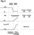
- block pressure As shown in the detail view in FIG. 4, without a movement of the lifting mechanism 2 (consumer volume flow 0), a predictable pressure occurs in the “lowering active ” area, which is referred to as “block pressure” in this application. As mentioned above, increasing the flow of fluid from the consumer (lift cylinder 4) to the tank T increases the “block pressure”, while decreasing the flow of fluid to the consumer reduces the "block pressure”.
- the increase in the "block pressure” can be influenced with increasing deflection and thus increasing pump quantity. This is quite evident in figure 5 shown, from which it can be seen that with increasing inflow volume and simultaneous increase in the outflow cross section 68 towards the tank T, the increase in the “block pressure” compared to the increase according to FIG figure 4 can be flattened so that the "block pressure” increases only moderately.
- the course of the cross section when the pressure medium connection is opened from the pressure chamber 8 ("carry") to the return (T) and the course of the opening cross section from the annular space 10 ("press") to the return (T) can also be varied .
- the full outflow cross section 68 effective in the "lowering" direction ie the cross section determining the pressure medium connection from the pressure chamber 8 to the tank T, must already be set to a maximum before the in figure 6 pressure control range indicated by dashed lines is reached.
- these areas can also overlap each other more or less.
- a valve arrangement and a method for controlling a lifting mechanism or attachment of a mobile working device are disclosed, with a double-acting lifting cylinder being controlled via a directional control valve.
- This is designed with two control edges, which simultaneously change an inflow cross section and an outflow cross section, so that, for example, a pressure setting on the lifting cylinder in the "lowering" direction is possible.
Landscapes
- Engineering & Computer Science (AREA)
- Physics & Mathematics (AREA)
- Fluid Mechanics (AREA)
- Mechanical Engineering (AREA)
- General Engineering & Computer Science (AREA)
- Fluid-Pressure Circuits (AREA)
Abstract
Description
- Die Erfindung betrifft eine Ventilanordnung zur Ansteuerung eines Hubwerks oder Anbaugeräts gemäß dem Oberbegriff des Patentanspruches 1 und ein Verfahren zur Ansteuerung eines derartigen Hubwerks oder Anbaugeräts.
- Derartige Ventilanordnungen werden beispielsweise zur Steuerung der Arbeitsfunktion von mobilen Arbeitsgeräten, insbesondere landwirtschaftlichen Nutzfahrzeugen wie Traktoren mit Krafthebern, Mähdreschern mit einer Mähtischregelung, Feldhäckslern mit einer Gebissregelung oder Kommunalmaschinen mit Krafthebern verwendet.
- So sind beispielsweise moderne Traktoren mit einem Heckhubwerk und einem Fronthubwerk ausgeführt, wobei die Druckmittelversorgung häufig nach einer LS-Regelung, d.h. in Abhängigkeit von dem höchsten Lastdruck der Verbraucher, erfolgt. Das Heck- oder auch das Fronthubwerk können dabei jeweils doppeltwirkend ausgeführt sein, wobei die beispielsweise in Richtung "Heben"/"Stützen" bzw. "Absenken"/"Drücken" wirksamen Druckräume eines Hubzylinders des Hubwerks über ein stetig verstellbares Wegeventil mit einer Druckmittelquelle bzw. einem Rücklauf verbindbar sind, um die jeweiligen Funktionen (Absenken, Drücken, Heben, Stützen, Neutralstellung oder Schwimmstellung) zu realisieren.
- Die Ansteuerung des stetig verstellbaren Wegeventils erfolgt dabei über ein elektrisches Steuergerät der Arbeitsmaschine, wobei die Sollwerte beispielsweise über ein Frontbedienteil oder ein Heckbedienteil des Arbeitsgerätes eingestellt werden.
- Bei diversen Arbeitsvorgängen, beispielsweise dem Senken mit kaltem Öl oder einem Lösen von verklemmten Fanghaken, und zum Betrieb diverser Anbaugeräte, beispielsweise Grubber, Packerwalzen, etc., ist es nötig, den in Richtung "Drücken" wirkenden Druckraum des Hubzylinders mit einem definierten hydraulischen Volumenstrom und limitiertem Druck zu beaufschlagen. Dies kann beispielsweise durch geeignete Ansteuerung des stetig verstellbaren Wegeventils und/oder über separate Druckregelventile (Druckbegrenzungs- oder Druckreduzierventil) erfolgen.
- In den Druckschriften
DE 10 2004 033 315 A1 undDE 10 2006 004 423 B4 sind gattungsgemäße Ventilanordnungen gezeigt, bei denen die Begrenzung des Drucks in dem in Richtung "Drücken"/"Senken" wirksamen Druckraum des Hubzylinders und den mit diesem verbundenen Druckmittelströmungspfaden über ein Druckbegrenzungsventil erfolgt. - Die beiden Druckschriften
DE 10 2017 219 942 A1 undEP 2 884 118 A1 zeigen jeweils gattungsgemäße Ventilanordnungen, bei denen die Limitierung des Drucks mittels eines Druckreduzierventils erfolgt. Eine ähnliche Lösung ist in derUS 10321621 B2 - In der Druckschrift
DE 101 38 389 A1 wird eine Ventilanordnung mit einem stetig verstellbaren Wegeventil beschrieben, das mit einer elektronischen Druckregelung ausgeführt ist. - Ein zur Ansteuerung derartiger Hubwerke geeignetes stetig verstellbares (doppelt wirkendes) Wegeventil ist in der
DE 10 2013 207 299 A1 gezeigt, wobei das Wegeventil Zwischenpositionen für passive Bewegungen, d.h. Bewegungen aufgrund der Schwerkraft oder dergleichen, aufweist. - Bei der Verwendung von hydromechanischen Ventilen zur Druckregelung, beispielsweise der oben genannten Druckbegrenzungs- oder Druckreduzierventile werden durch die zusätzlichen Druckregelventile die Systemkosten erhöht.
- Dieser Nachteil ist bei den weiterhin beschriebenen Lösungen mit einer Einregelung des Drucks über das Wegeventil, wobei als Feedbackgröße beispielsweise ein Drucksensorwert herangezogen wird, beseitigt. Ein Nachteil besteht jedoch darin, dass die Performance der Regelung hochgradig abhängig ist von der Signalverarbeitungskette: Drucksensor - Verarbeitung im Regelalgorithmus-Ansteuerung der Ventils - Reaktion des Ventils und ggf. noch Dynamik der Druckversorgung. Hinzukommt, dass ein Ventilschieber des stetig verstellbaren Wegeventils bei der Regelung eine Neutralstellung durchfahren muss, was regelungstechnisch störend wirkt.
- Demgegenüber liegt der Erfindung die Aufgabe zugrunde, eine Ventilanordnung und ein Verfahren zur Ansteuerung eines mobilen Arbeitsgeräts zu schaffen, bei dem die Druckbegrenzung gegenüber den eingangs beschriebenen Lösungen vereinfacht ist.
- Diese Aufgabe wird im Hinblick auf die Ventilanordnung durch die Merkmalskombination des Patentanspruches 1 und im Hinblick auf das Verfahren durch die Merkmale des nebengeordneten Patentanspruches 11 gelöst.
- Vorteilhafte Weiterbildungen der Erfindung sind Gegenstand der Unteransprüche.
- Die erfindungsgemäße Ventilanordnung bzw. das Erfindungsgemäße Verfahren sind zur Ansteuerung eines Hubzylinders eines Hubwerks oder Anbaugeräts eines mobilen Arbeitsgeräts, insbesondere eines landwirtschaftlichen Nutzfahrzeuges ausgelegt und hat ein proportional/stetig verstellbares Wegeventil. Dieses hat einen ersten Arbeitsanschluss, der in Druckmittelverbindung mit einem in einer ersten Betätigungsrichtung (bspw. Heben) wirksamen Druckraum des Hubzylinders steht. Ein weiterer Arbeitsanschluss steht in Druckmittelverbindung mit einem zweiten, in einer zweiten Betätigungseinrichtung (bspw. Senken) wirksamen Druckraum des Hubzylinders. Das Wegeventil hat des Weiteren einen Rücklauf-/Tankanschluss und einen Druckanschluss, wobei durch Verstellen eines Schiebers des Wegeventils Öffnungsquerschnitte (Messblenden) zwischen den Anschlüssen auf- bzw. zusteuerbar sind, um die Druckmittelversorgung zum bzw. vom Hubzylinder zu steuern. Erfindungsgemäß ist der Schieber mit zwei Aktiv-Senken-Steuerkanten ausgeführt, über die beim Verstellen des Schiebers ein Zulaufquerschnitt in Richtung zu einem der Druckräume aufsteuerbar ist und gleichzeitig, vorzugsweise gegenläufig, ein Ablaufquerschnitt im Druckmittelströmungspfad von dem Druckraum in Richtung zum Rücklaufanschluss (Tank) auf- bzw. zusteuerbar ist. Demgemäß wird beim Verstellen des Wegeventils in den Aktiv-Senken-Bereich durch den Schieber eine eigene Druckregelstellung eingenommen, in der sich ein dynamisches Druckgleichgewicht einstellt, das abhängig ist von den über die Aktiv-Senken-Steuerkanten aufgesteuerten Zulauf- und Ablaufquerschnitten. Dadurch ergibt sich ohne Hubwerksbewegung und damit einhergehender "Volumenstromstörung" über die den Ablaufquerschnitt bestimmende Ablaufkante in einer bestimmten Schieberposition ein definierter Druckabfall, der beim erfindungsgemäßen Konzept "Blockdruck" genannt wird. Durch Variation der Schieberauslenkung und somit der Verstellung der genannten Öffnungsquerschnitte kann dann direkt der "Blockdruck" ohne Hubwerksbewegung eingestellt werden.
- Mit einfachen Worten gesagt, ist bei der Verstellung des Schiebers in den Aktiv-Senken-Bereich der in Richtung "Drücken"/"Senken" wirksame Druckraum des Zylinders mit einem zulaufenden Druckmittelvolumenstrom beaufschlagt, wobei gleichzeitig auch ein definierter Ablaufquerschnitt vorhanden ist, so dass sich ein vorhersehbarer "Blockdruck" einstellt, wobei der Verbrauchervolumenstrom gleich Null ist. Dabei wird durch eine Vergrößerung des Volumenstroms von dem Druckraum (Ablaufquerschnitt aufgesteuert) der "Blockdruck" erhöht. Bei Erhöhung des Druckmittelvolumenstroms zum Verbraucher (Vergrößern des Zulaufquerschnitts) wird entsprechend der "Blockdruck" verringert.
- Gemäß einer vorteilhaften Weiterbildung der Erfindung ist das Wegeventil neben dem vorbeschriebenen "Aktiv-Senken"-Schieberverstellbereich mit Verstellbereichen "Schwimmstellung" und/oder "Neutral" und/oder "Passiv-Senken" und/oder "Heben" ausgeführt.
- Dabei kann der Schieberverstellbereich "Aktiv-Senken" benachbart zum Schieberverstellbereich "Passiv-Senken" ausgeführt sein. Dies ermöglicht es, einen kontinuierlichen, überlappenden Übergang zwischen beiden Verstellbereichen auszubilden.
- Ein lastdruckunabhängiger Volumenstrom lässt sich durch Ausgestaltung der Ventilanordnung als LS-Ventilanordnung mit einer dem Wegeventil vorgeschalteten LS-Druckwaage und einem LS-Druckregler der Pumpe ausbilden.
- Zur weiteren Verbesserung der Betriebssicherheit kann in einem Druckmittelströmungspfad zwischen einem oder beiden Arbeitsanschlüssen und jeweils damit verbundenen Druckraum/Druckräumen ein Druckbegrenzungsventil vorgesehen sein.
- Durch dieses Druckbegrenzungsventil (Sekundär-Druckbegrenzungsventil) können durch Störungen induzierte Überdrucksituationen abgefangen werden, so dass bei einer derartigen Situation Druckmittel in Richtung Rücklauf geführt werden kann. Dies kann zum Beispiel dann notwendig sein, wenn das Hubwerk aufgrund einer Bodenkontur nach oben ausweichen muss.
- Die Funktionalität des erfindungsgemäßen Verfahrens und der erfindungsgemäßen Ventilanordnung lässt sich weiter verbessern, wenn ein Positionssensor vorgesehen wird, über den die Position des Hubwerks/Anbaugeräts erfasst wird. Dieser Positionssensor kann beispielsweise den Hub des Hubzylinders, einen Hubwerkswinkel oder dergleichen erfassen. Prinzipiell kann mit dem Signal dieses Positionssensors der theoretische Volumenstrom oder alternativ die Hubwerksgeschwindigkeit berechnet werden, so dass bei Abweichungen von Sollwerten in die Steuerung eingegriffen werden kann. Hierauf wird noch später eingegangen.
- Eine weitere oder zusätzliche Möglichkeit, um aufgrund von Störungen erforderliche Eingriffe in die Regelung vorzunehmen, besteht darin, einen Drucksensor einzusetzen, über den der Druck in dem jeweiligen Druckraum des Hubzylinders bzw. in dem zu diesem führenden Druckmittelströmungspfad erfasst wird. In Abhängigkeit vom Signal dieses Drucksensors kann dann über einen Regelalgorithmus mittels einer Steuereinheit die Schieberposition entsprechend der Regelabweichung korrigiert werden. Auch dieses Konzept wird bei der konkreten Beschreibung näher erläutert.
- Die Ansteuerung des Wegeventils ist besonders einfach, wenn dieses elektrohydraulisch ansteuerbar ausgeführt ist.
- Das Abstützen des Hubzylinders in einer vorbestimmten Sollposition ist verbessert, wenn ein entsperrbares Rückschlagventil dem in Abstützrichtung wirksamen Druckraum zugeordnet ist. Dieses kann mechanisch oder hydraulisch in Öffnungsstellung gebracht werden, um das Abströmen des Druckmittels zu ermöglichen. Dabei kann beispielsweise der Hub des Schiebers über eine Koppelmechanik auf das Rückschlagventil übertragen werden, um dieses aufzusteuern.
- Bevorzugte Ausführungsbeispiele der Erfindung werden im Folgenden anhand schematischer Zeichnungen näher erläutert. Es zeigen:
-
Figur 1 einen vereinfachten Hydraulikschaltplan einer Ventilanordnung zur Ansteuerung eines Hubwerks; -
Figur 2 eine Detaildarstellung eines Wegeventils der Ventilanordnung gemäßFigur 1 ; -
Figur 3 eine qualitative Darstellung der sich bei der Verstellung des Wegeventils gemäßFigur 2 einstellenden Querschnittsverläufe; -
Figur 4 einen Teilbereich der Darstellung gemäßFigur 3 , wobei der Verlauf eines "Blockdrucks" dargestellt ist, der sich nach dem erfindungsgemäßen Konzept einstellt; -
Figur 5 eine Darstellung gemäßFigur 3 , bei der der "Blockdruck" durch eine geeignete Ansteuerung des Wegeventils vergleichsweise moderat ansteigt und -
Figur 6 eine ebenfalls aufFigur 3 basierende Darstellung, in der die Querschnittsverläufe im Hinblick auf eine Varianz der Rücklaufkennlinien modifiziert sind. - Die Erfindung wird im Folgenden anhand einer Hubwerksanordnung eines Traktors erläutert. Prinzipiell lässt sich die erfindungsgemäße Ventilanordnung jedoch auch bei anderen doppeltwirkenden Verbrauchern eines mobilen Arbeitsgerätes einsetzen.
- Moderne Traktoren sind, wie eingangs erläutert, mit einem Hubwerk 2 ausgeführt, das einen doppeltwirkenden Hubzylinder 4 (auch Hubwerkszylinder genannt) aufweist, der über eine erfindungsgemäße Ventilanordnung 6 angesteuert wird. Beim dargestellten Ausführungsbeispiel ist der Hubzylinder 4 als Differentialzylinder mit einem bodenseitigen Druckraum 8 und einem Ringraum 10 ausgeführt, die über die Ventilanordnung 6 mit einer Verstellpumpe 12 oder einer Druckmittelsenke, im vorliegenden Fall einem Tank T verbindbar sind. Beim dargestellten Ausführungsbeispiel ist das Hubwerk 2 als Heckhubwerk ausgeführt, wobei eine Kolbenstange 14 des Hubzylinders 4 einen schwenkbar an einer Hubwelle 16 gelagerten Arm 18 sowie weitere Koppelelemente betätigt, an denen beispielsweise ein Anbaugerät, wie eine Packerwalze 20, eine Drillmaschine oder ein Pflug angebaut ist.
- Die dargestellte Ventilanordnung 6 zur Ansteuerung des Hubwerks 2 ist als LS-Steuerung mit einem Messblenden ausbildenden stetig verstellbaren Wegeventil 22 und einer diesen vorgeschalteten LS-Druckwaage 24 ausgebildet. In an sich bekannter Weise ist durch eine derartige LS-Steuerung gewährleistet, dass der Druck vor der jeweils aufgesteuerten Messblende unabhängig vom Pumpendruck nur um eine bestimmte Druckdifferenz über den individuellen Lastdruck liegt. Die Erfindung setzt jedoch keinesfalls eine derartige LS-Steuerung voraus.
- Gemäß dem Hydraulikschaltplan in
Figur 1 ist der Druckanschluss, der beispielsweise als Axialkolbenpumpe ausgeführten Verstellpumpe 12 über einen Zulaufkanal 26 mit einem Druckanschluss P' der Druckwaage 24 verbunden. Diese ist über eine Feder 28 in eine Grundposition vorgespannt, in der ein Ausgangsanschluss D der Druckwaage 24 abgesperrt ist. Der Druck im Zulaufkanal 26 wird über einen Steuerkanal 30 abgegriffen und zu einer in Öffnungsrichtung, entgegen der Kraft der Feder 18 wirksamen Steuerfläche der Druckwaage 24 geführt. In Gegenrichtung wirkt, wie erwähnt, die Feder 28 sowie der Druck in einem LS-Kanal 32. Dieser ist mit dem Druck stromabwärts der jeweils durch das Wegeventil 22 aufgesteuerten Messblende beaufschlagt. In Abhängigkeit von dieser Messblendenöffnung stellt sich die Druckwaage 24 in eine Regelposition ein, in der der Druckabfall über der Messblende konstant gehalten wird und in etwa dem Druckäquivalent der Kraft der Feder 28 entspricht, so dass ein konstanter Druckmittelvolumenstrom über die Messblende (Wegeventil 22) gewährleistet ist. - Der im Zulaufkanal 26 anliegende Förderdruck der Verstellpumpe 4 wird bei einer LS-Steuerung in Abhängigkeit von dem höchsten, an den Verbrauchern des Traktors anliegenden Lastdruck eingestellt. Dieser Lastdruck - beim dargestellten Ausführungsbeispiel der Lastdruck am Hubzylinder 4 - wird an einen LS-Druckregler 34 gemeldet, über den in an sich bekannter Weise die Einstellung der Verstellpumpe erfolgt. Eine derartige LS-Steuerung, bei der der Förderstrom der Pumpe in Abhängigkeit vom höchsten Lastdruck eingestellt wird, ist jedoch, wie oben erwähnt, keine Voraussetzung für das erfindungsgemäße System.
- Ein Ausgangsanschluss D der Druckwaage 24 ist über eine Zulaufleitung 36 mit einem Druckanschluss P des Wegeventils 22 verbunden. Dieses hat des Weiteren einen Rücklaufanschluss T, einen LS-Entlastungsanschluss LSE sowie einen weiteren Druckanschluss P', wobei dieser und der LS-Entlastungsanschluss LSE in Druckmittelverbindung mit der LS-Leitung 32 stehen. Dem LS-Entlastungsanschluss LSE ist ein LS-Ausgangsanschluss LSR zugeordnet, der seinerseits über eine LS-Rücklaufleitung 43 mit dem Tank T verbunden ist. Wie im Folgenden noch näher erläutert wird, kann durch Aufsteuern der LS-Rücklaufleitung eine LS-Druckentlastung durchgeführt werden.
- Das Wegeventil 22 hat des Weiteren einen Ausgangsanschluss P‴, der über einen Kanal 38 mit dem Druckanschluss P' und damit auch mit der LS-Leitung 32 verbunden ist. Ein Arbeitsanschluss A ist über einen Arbeitsleitung 40 mit dem bodenseitigen Druckraum 8 des Hubzylinders 4 verbunden. Ein weiterer Arbeitsanschluss B ist über eine Arbeitsleitung 42 mit dem von der Kolbenstange 14 durchsetzten Ringraum 10 des Hubzylinders 4 verbunden.
- In der Darstellung gemäß
Figur 1 ist ein Schieber 44 des Wegeventils 22 über Zentrierfedern 46, 48 in eine Neutralstellung vorgespannt, die im Folgenden anhandFigur 2 näher erläutert wird. - Die Verstellung des Wegeventils 22 erfolgt über eine Pilotventilanordnung 50, die in der Darstellung gemäß
Figur 1 durch zwei elektrohydraulische Vorsteuerelemente 52, 54 gebildet ist. Die Ansteuerung der Pilotventilanordnung 54 erfolgt dabei mittels einer Steuereinheit 56, die mit einer geeigneten Regelungssoftware ausgeführt ist. Das zur Ansteuerung der Pilotventilanordnung 50 erforderliche Steueröl wird über eine Steuerölversorgung 58 bereitgestellt, die über eine Pilotleitung 60 mit den beiden Vorsteuerelementen 52, 54 verbunden ist. Das für die Betätigung der Pilotventilanordnung 50 erforderliche Steueröl kann über die LS-Rücklaufleitung 43 zum Tank T abgeführt werden. - Die Position des Schiebers 44 wird über einen Wegaufnehmer 62 erfasst und zur Steuereinheit 56 gemeldet, so dass die Ansteuerung der Pilotventilanordnung 50 auch in Abhängigkeit vom Signal des Wegaufnehmers 62 erfolgt.
- Weitere Einzelheiten des Wegeventils 22 werden anhand der vergrößerten Darstellung in
Figur 2 erläutert. - Wie vorstehend ausgeführt, ist der Schieber 44 des Wegeventils 22 über die beiden Zentrierfedern 46, 48 in eine Neutralstellung N vorgespannt, in der die Anschlüsse P, P", P'" und A abgesperrt sind. Der Arbeitsanschluss B ist mit dem Tankanschluss T verbunden, so dass das Druckmittel von der Arbeitsleitung 42 über einen Tankkanal 64 zum Tank T hin abströmen kann. Des Weiteren sind die LS-Entlastungsanschlüsse LSE und LSR mit einander verbunden, so dass auch die LS-Leitung zum Tank T hin entlastet ist.
- Bei einer Verstellung des Ventilschiebers 44 nach links (Ansicht nach
Figur 2 ) in den Bereich "Heben" wird eine die beiden Anschlüsse P und P'" verbindende Messblende 65 aufgesteuert, so dass Druckmittel vom Druckanschluss P über den Anschluss P'" und den Kanal 38 zum Druckanschluss P" strömen kann und dann von dort über den Arbeitsanschluss A und die Arbeitsleitung 40 in den bodenseitigen Druckraum 8 des Hubzylinders 4 gefördert wird. Dessen Ringraum 10 ist über die Arbeitsleitung 42, den Arbeitsanschluss B, den Tankanschluss T und den Tankkanal 64 mit dem Tank T verbunden, so dass das Druckmittel aus dem sich verkleinernden Ringraum 10 abströmen kann. Der Kolben des Hubzylinders 4 fährt aus und das Arbeitsgerät wird entsprechend angehoben oder zumindest abgestützt. - Bei einer Verstellung des Ventilschiebers 44 aus seiner in
Figur 2 dargestellten Grundposition nach rechts wird dieser in einen "Senkenpassiv-(Spassiv)-Bereich" verstellt, in dem die Anschlüsse P, P'" und P" abgesperrt sind. Die beiden Arbeitsanschlüsse A, B sind beide mit dem Tankanschluss T verbunden. Auch die LS-Druckentlastung ist zur LS-Rücklaufleitung 43 hin geöffnet, so dass das Anbaugerät, im vorliegenden Fall die Packerwalze 20 aufgrund des Eigengewichtes den Hubzylinder 4 in Einfahrrichtung beaufschlagt ist, so dass entsprechend das Druckmittel aus dem sich verkleinernden Druckraum 8 zum Tank T hin verdrängt wird. Aus diesem kann Druckmittel in den sich vergrößernden Ringraum 10 nachströmen. - Bei einer weiteren Verstellung des Schiebers 44 wird der "Senkenaktiv-(Saktiv)-Bereich" erreicht, in dem, ähnlich wie im Heben-Bereich, die beiden Anschlüsse P und P‴ mit einander verbunden sind, so dass Druckmittel von der Zulaufleitung 36 über die Messblende 65 in den Kanal 38 geführt wird. In dem Saktiv-Bereich ist durch eine Steuerkante des Schiebers 44 ein Zulaufquerschnitt 66 zwischen den Anschlüssen P" und B aufgesteuert. Gleichzeitig oder zumindest überlappend ist über eine weitere Steuerkante ein Ablaufquerschnitt 68 geöffnet, durch den der Arbeitsanschluss B und somit der in Richtung "Senken/Drücken" wirksame Ringraum 10 mit dem Tank T verbunden ist. Die Verstellung der Querschnitte 66, 68 erfolgt vorzugsweise gegenläufig.
- Wie eingangs erläutert, ergibt sich dabei ohne Hubwerksbewegung über diesen Ablaufquerschnitt 68 in einer bestimmten Schieberauslenkung ein definierter Druckabfall, wobei durch Variation der Schieberauslenkung, d.h. durch Auf- oder Zusteuern des Zulaufquerschnitts 66 bzw. der Ablaufquerschnitts 68 dieser definierte Druckabfall ("Blockdruck") variiert werden kann. Der Zulaufquerschnitt 66 und der Ablaufquerschnitt 68 ändern sich dabei vorzugsweise gegenläufig, so dass entsprechend bei einer Erhöhung des Volumenstroms vom Verbraucher der "Blockdruck" erhöht wird, während bei einer Verringerung des Volumenstroms zum Verbraucher der "Blockdruck" verringert wird. Je nach Schieberauslenkung stellt sich somit ein dynamisches Druckgleichgewicht ein, wodurch eine feine Druckeinstellung am Hubzylinder 4 in Richtung "Senken" möglich ist.
- Bei einem weiteren Verstellen des Schiebers 44 nach rechts (Ansicht nach
Figur 2 ) wird eine Schwimmstellung ("Float") eingestellt, in der die beiden Arbeitsanschlüsse A, B beide mit dem Tank T verbunden ist. Des Weiteren ist die LS-Druckentlastung wirksam. - In dieser Schwimmstellung ist das Hubwerk 2 nicht mit einer Kraft beaufschlagt, so dass das Arbeitsgerät lediglich aufgrund seines Eigengewichtes auf dem Boden aufliegt.
- Um ein unerwünschtes Absinken des Hubzylinders 4 zu verhindern, ist bei dem in
Figur 1 dargestellten Ausführungsbeispiel in der Arbeitsleitung 40 ein entsperrbares Rückschlagventil 70 vorgesehen, das in seiner Schließstellung ein Abströmen von Druckmittel aus dem Druckraum 8 verhindert. Das Rückschlagventil 70 kann beim Verstellen des Schiebers 44 in die Bereiche "Float" und "Senkenaktiv/passiv" mechanisch, elektrisch oder hydraulisch geöffnet werden. Dies kann beispielsweise dadurch erfolgen, dass der Schieber 44 mechanisch mit dem Rückschlagventil 70 gekoppelt ist, so dass dieses bei einer Verstellung des Schiebers 44 in die vorgenannten Bereiche aufgesteuert wird. Selbstverständlich ist auch eine hydraulische oder elektromechanische Betätigung möglich. - Anstelle des Rückschlagventils 70 können entsprechende Rückschlagventile auch in das Wegeventil 22 integriert werden. Diese dienen insbesondere dazu, ein Absinken des Anbaugeräts/Krafthebers aufgrund einer Leckage zu vermeiden.
- Bei einem Ausführungsbeispiel der Erfindung kann gemäß
Figur 1 optional ein Drucksensor 72 vorgesehen werden, über den der Druck im Ringraum 10 bzw. in der Arbeitsleitung 42 erfasst und an die Steuereinheit 56 gemeldet wird. Bei einer Abweichung des Signals des Drucksensors 72 von Sollwerten, beispielsweise bedingt durch eine ungenaue Auslenkung des Schiebers 44 oder sonstige Störungen, kann dann über den Regelalgorithmus der Steuereinheit 56 die Schieberposition entsprechend der Regelabweichung korrigiert werden. Um einen zu hohen Druck aufgrund von Druckmittelvolumenströmen effizient abzubauen, kann bei dieser Regelung der Bereich "Senkenpassiv" miteinbezogen werden, um nur noch eine Steuerkantenöffnung in Richtung "Tank/Rücklauf" ohne zulaufendes Druckmittel zu nutzen. Dies wird zum Beispiel dann notwendig, wenn das Anbaugerät wegen einer ansteigenden Bodenkontur bei gleichbleibendem Druck/Bodeneintauchtiefe ausweichen muss. - Um durch Störungen induzierte Überdrucksituationen abzufangen, kann erfindungsgemäß ein Sekundär-Druckbegrenzungsventil 74, 76 vorgesehen werden, über das der Druck in der Arbeitsleitung 42 bzw. der Arbeitsleitung 40 begrenzt ist, so dass das Druckmittel bei Überschreiten des am Druckbegrenzungsventil 74, 76 eingestellten Drucks Druckmittel in Richtung zum Tank T ablässt. Dies kann beispielsweise dann notwendig sein, wenn das Hubwerk 2 aufgrund einer Bodenkontur ausweichen muss, so dass dann das Druckbegrenzungsventil 74 in der Arbeitsleitung 42 öffnet.
- Eine weitere Option besteht darin, die Auslenkung des Hubzylinders 4 durch einen Positionssensor 78 zu erfassen. Bei dem Ausführungsbeispiel gemäß
Figur 1 ist dieser als Winkelsensor ausgeführt, mit dem der Anstellwinkel des Arms 18 erfasst wird. Dadurch ist es beispielsweise möglich, den theoretischen Volumenstrom auf der "Drücken-Seite" (alternativ die Zylindergeschwindigkeit/Hubwerksgeschwindigkeit, die über große Bereiche annähernd proportional sind) zu berechnen. In Kenntnis dieses theoretischen Volumenstroms können beispielsweise folgende Verbesserungen des Systems bewirkt werden. - So kann beim Senken bis zu einem theoretischen Volumenstrom aktiv mit Pumpenvolumenstrom nachgefüllt werden, ohne einen Druckaufbau zu bewirken. Sinnvoller Weise wird aufgrund von Toleranzen dieser theoretische Volumenstrom nicht komplett ausgenutzt.
- Der damit einhergehende Vorteil ist eine bessere Füllung des Hubzylinders 4, so dass der Übergang zur Druckregelung kontinuierlich ausgeführt ist. Ein weiterer Vorteil besteht darin, dass beim Senken der Schieber 44 weiter ausgelenkt werden kann, ohne Druck aufzubauen. Damit kann eventuell die einfachwirkende Senkengeschwindigkeit maximiert werden, da dann die den Ablaufquerschnitt 68 bestimmende Steuerkante vollständig geöffnet ist.
- Eine weitere Verbesserung besteht darin, dass beim Ausweichen durch eine Bodenkontur abhängig von dem theoretischen Druckmittelvolumenstrom und dem Solldruck der Tankablauf auf der "Drücken-Seite" gesteuert geöffnet werden kann. Der Vorteil dabei ist, dass beim Ausweichen auch ohne "closed-loop-Druckregelung" der Druck nur moderat ansteigt bzw. bei einem System mit Druckregelung der Regler durch die Vorsteuerung unterstützt wird.
- Des Weiteren ist es möglich, beim Senken in der "Drücken-Druckregelung" den Volumenstrom durch Zurückregeln des "Drücken-Drucks" zu begrenzen. In dem Fall, in dem der "Drücken-Druck" bereits 0 bar ist und das Hubwerk 2 immer noch zu schnell ist, kann die Schieberposition weiter verändert werden, um das "Tragen" der Ablaufkante zum Tank T hin zusätzlich zu schließen. Dies entspricht dann einer Umschaltung in den "Senken-Bereich" ohne Druckregelung.
- Bei einem "Senken" ohne Druckregelung kann automatisch in die "Drücken-Druckregelung" umgeschaltet werden, wenn der Volumenstrom eine Mindestgeschwindigkeit unterschreitet.
- Zur weiteren Verdeutlichung sind in der
Figur 3 qualitativ Querschnittsverläufe dargestellt, die sich bei der vorbeschriebenen Verstellung des Schiebers 44 einstellen. Die Bereiche "Heben", "Neutral" und "Freigang/Float", insbesondere deren genauer Beginn und die Steigungen, sind in dieser Abbildung nur beispielhaft dargestellt. - Der in
Figur 3 obere Querschnittsverlauf zeigt den Öffnungsquerschnitt in den vorbeschriebenen Stellbereichen des Schiebers 44 zwischen dem Druckraum 8 ("Tragen") und dem Rücklauf (T). Dementsprechend wird dieser Querschnitt in den beiden "Senken-Bereichen" aufgesteuert und ist dann im Freigang ("Float") geöffnet. - Der Öffnungsquerschnitt von der Pumpe 12 in Richtung zum Druckraum 8 ("Tragen") ist lediglich in dem Bereich "Heben" aufgesteuert und verringert sich mit zunehmender Verstellung des Schiebers 44 in Richtung "Neutral".
- Gemäß dem erfindungsgemäßen Konzept wird zum Ende des Verstellbereiches "Senkenpassiv" ein definierter Ablaufquerschnitt 68 vom Ringraum 10 ("Drücken") zum Rücklauf (T) aufgesteuert. Dieser Querschnitt wird dann beim Übergang vom Bereich "Senkenaktiv" in den Bereich Freigang ("Float") wieder geschlossen.
- In dem Verstellbereich "Senkenaktiv" wird dann entsprechend den vorstehenden Ausführungen ein Zulaufquerschnitt aufgesteuert, der die Druckmittelverbindung zwischen der Pumpe 12 und dem Ringraum 10 ermöglicht und der dann im Bereich Freigang ("Float") wieder geschlossen wird.
- In diesem Bereich sind dann beide Druckräume 8 ("Tragen") und 10 ("Drücken") mit dem Tank T verbunden, so dass Druckmittel umströmen kann.
- Wie in der Detaildarstellung inFigur 4 gezeigt, stellt sich ohne eine Bewegung des Hubwerks 2 (Verbrauchervolumenstrom 0) in dem Bereich "Senkenaktiv" ein vorhersehbarer Druck ein, der in dieser Anmeldung "Blockdruck" genannt ist. Wie vorstehend erwähnt, wird durch eine Erhöhung des Druckmittelvolumenstroms vom Verbraucher (Hubzylinder 4) zum Tank T der "Blockdruck" erhöht, während eine Verringerung des Druckmittelvolumenstroms zum Verbraucher den "Blockdruck" verringert.
- Durch geeignete Einstellung des Ablaufquerschnitts zum Tank T hin kann mit steigender Auslenkung und damit steigender Pumpenmenge die Steigung des "Blockdrucks" beeinflusst werden. Dies ist recht anschaulich in
Figur 5 dargestellt, aus der hervorgeht, dass mit steigender Zulaufmenge und gleichzeitiger Vergrößerung des Ablaufquerschnitts 68 zum Tank T hin das Ansteigen des "Blockdrucks" gegenüber dem Anstieg gemäßFigur 4 abgeflacht werden kann, so dass der "Blockdruck" lediglich moderat ansteigt. - Wie in
Figur 6 angedeutet, kann im Bereich "Senkenaktiv" der Querschnittsverlauf bei dem Aufsteuern der Druckmittelverbindung vom Druckraum 8 ("Tragen") zum Rücklauf (T) sowie der Verlauf des Öffnungsquerschnitts vom Ringraum 10 ("Drücken") zum Rücklauf (T) auch variiert werden. So kann, wie inFigur 6 gestrichelt angedeutet, der volle in Richtung "Senken" wirksame Ablaufquerschnitt 68, d.h. der die Druckmittelverbindung vom Druckraum 8 zum Tank T bestimmende Querschnitt, bereits auf ein Maximum eingestellt sein, bevor der inFigur 6 gestrichelt angedeutete Druckregelbereich erreicht wird. Wie inFigur 6 bei den mit dem Begriff "Varianz" gekennzeichneten Öffnungs-Querschnittsverläufen angedeutet, können diese Bereiche auch einander mehr oder weniger überlappen. - Offenbart sind eine Ventilanordnung und ein Verfahren zur Ansteuerung eines Hubwerks oder Anbaugeräts eines mobilen Arbeitsgeräts, wobei ein doppelt wirkender Hubzylinder über ein Wegeventil angesteuert wird. Dieses ist mit zwei Steuerkanten ausgebildet, die gleichzeitig einen Zulaufquerschnitt und einen Ablaufquerschnitt ändern, so dass beispielsweise eine Druckeinstellung am Hubzylinder in Richtung "Senken" möglich ist.
-
- 2
- Hubwerk
- 4
- Hubzylinder 4
- 6
- Ventilanordnung
- 8
- Druckraum
- 10
- Ringraum
- 12
- Verstellpumpe
- 14
- Kolbenstange
- 16
- Hubwelle
- 18
- Arm
- 20
- Packerwalze
- 22
- Wegeventil
- 24
- Druckwaage
- 26
- Zulaufkanal
- 28
- Feder
- 30
- Steuerkanal
- 32
- LS-Leitung
- 34
- LS-Druckregler
- 36
- Zulaufleitung
- 38
- Kanal
- 40
- Arbeitsleitung
- 42
- Arbeitsleitung
- 43
- LS-Rücklaufleitung
- 44
- Schieber
- 46
- Zentrierfeder
- 48
- Zentrierfeder
- 50
- Pilotventilanordnung
- 52
- Vorsteuerelement
- 54
- Vorsteuerelement
- 56
- Steuereinheit
- 58
- Steuerölversorgung
- 60
- Pilotleitung
- 62
- Wegaufnehmer
- 64
- Tankkanal
- 65
- Messblende
- 66
- Zulaufquerschnitt
- 68
- Ablaufquerschnitt
- 70
- Rückschlagventil
- 72
- Drucksensor
- 74
- Druckbegrenzungsventil
- 76
- Druckbegrenzungsventil
- 78
- Positionssensor
Claims (11)
- Ventilanordnung zur Ansteuerung eines Hubwerks oder eines Anbaugeräts eines mobilen Arbeitsgeräts, insbesondere eines landwirtschaftlichen Nutzfahrzeugs, mit einem stetig verstellbaren Wegeventil (22), das einen Arbeitsanschluss (A) hat, der in Druckmittelverbindung mit einem in einer ersten Betätigungsrichtung ("Heben") wirksamen Druckraum (8) des Hubzylinders (4) steht und das einen weiteren Arbeitsanschluss (B) hat, der in Druckmittelverbindung mit einem zweiten, in einer zweiten Betätigungsrichtung ("Senken") wirksamen Druckraum (10) des Hubzylinders (4) steht, wobei das Wegeventil (22) einen Tankanschluss (T) und einen Druckanschluss (P) hat, wobei durch Verstellen eines Schiebers (44) des Wegeventils (22) Öffnungsquerschnitte zwischen den Anschlüssen auf- bzw. zusteuerbar sind, dadurch gekennzeichnet dass der Schieber (44) zwei Aktiv-Senken-Steuerkanten hat, über die beim Verstellen des Schiebers (44) in einen Aktiv-Senken-Bereich (Senkenaktiv) ein Zulaufquerschnitt (66) in Richtung zu einem der Druckräume (8, 10) und gleichzeitig ein Ablaufquerschnitt (68) von dem Druckraum (8, 10) in Richtung zu dem Tankanschluss (T), vorzugsweise gegenläufig, auf- oder zusteuerbar ist.
- Ventilanordnung nach Patentanspruch 1, wobei das Wegeventil (22) einen Schieberverstellbereich "Schwimmstellung" und/oder "Neutral" und/oder "Passiv-Senken" (Senkenpassiv) und/oder "Heben" hat.
- Ventilanordnung nach Patentanspruch 2, wobei der Schieberverstellbereich "Aktiv-Senken" (Senkenaktiv) benachbart zum Schieberverstellbereich "Passiv-Senken" (Senkenpassiv) ist.
- Ventilanordnung nach einem der vorhergehenden Patentansprüche, wobei in einem Zulauf zum Wegeventil (22) eine LS-Druckwaage (24) vorgesehen ist.
- Ventilanordnung nach einem der vorhergehenden Patentansprüche, mit einem Druckbegrenzungsventil (74, 76) in einem Druckmittelströmungspfad zwischen einem Arbeitsanschluss (A, B) und dem damit verbundenen Druckraum (8, 10).
- Ventilanordnung nach einem der vorhergehenden Patentansprüche, mit einem Positionssensor (78) zur Erfassung einer Position des Hubwerks/Anbaugeräts.
- Ventilanordnung nach einem der vorhergehenden Patentansprüche, mit einem Drucksensor (72) im Druckmittelströmungspfad zu einem der Druckräume (8, 10).
- Ventilanordnung nach Patentanspruch 6 oder 7, mit einer Steuereinheit (56), die ausgelegt ist, vorzugsweise nach Art einer "closed-loop-Regelung", in Abhängigkeit vom Drucksignal des Drucksensors (72) und/oder in Abhängigkeit vom Signal des Positionssensors (76) die Schieberposition zu verstellen/korrigieren.
- Ventilanordnung nach einem der vorhergehenden Patentansprüche, wobei das Wegeventil (22) elektrohydraulisch angesteuert ist.
- Ventilanordnung nach einem der vorhergehenden Patentansprüche, mit zumindest einem im Druckmittelströmungspfad zum ersten Druckraum (8) angeordneten oder ins Wegeventil (22) integrierten entsperrbaren Rückschlagventil (70).
- Verfahren zur Ansteuerung eines Hubwerks oder eines Anbaugeräts eines mobilen Arbeitsgeräts, insbesondere eines landwirtschaftlichen Nutzfahrzeugs, mit einem stetig verstellbaren Wegeventil (22), das einen Arbeitsanschluss (A) hat, der in Druckmittelverbindung mit einem in einer ersten Betätigungsrichtung ("Heben") wirksamen Druckraum (8) steht, und das einen weiteren Arbeitsanschluss (B), der in Druckmittelverbindung mit einem zweiten, in einer zweiten Betätigungsrichtung ("Senken") wirksamen Druckraum (10) steht, wobei das Wegeventil (22) des Weiteren einen Tankanschluss (T) und einen Druckanschluss (P) hat, wobei durch Verstellen eines Schiebers (44) des Wegeventils (22) Öffnungsquerschnitte zwischen den Anschlüssen auf- bzw. zusteuerbar sind, mit den Schritten:- Verstellen des Schiebers (44) in einen Aktiv-Senken-Verstellbereich (Senkenaktiv), in dem- über eine erste "Aktiv-Senken-Steuerkante" ein Zulaufquerschnitt (66) zu einem in Richtung "Senken" wirksamen Druckraum (10) aufgesteuert und gleichzeitig oder überlappend über eine zweite "Aktiv-Senken-Steuerkante" ein Ablaufquerschnitt (68) vom Druckraum (8) zum Tank (T) auf- oder zugesteuert wird, so dass sich ein dynamisches Druckgleichgewicht einstellt.
Applications Claiming Priority (1)
| Application Number | Priority Date | Filing Date | Title |
|---|---|---|---|
| DE102020208922.1A DE102020208922B3 (de) | 2020-07-16 | 2020-07-16 | Ventilanordnung |
Publications (2)
| Publication Number | Publication Date |
|---|---|
| EP3940246A1 true EP3940246A1 (de) | 2022-01-19 |
| EP3940246B1 EP3940246B1 (de) | 2025-02-26 |
Family
ID=76890864
Family Applications (1)
| Application Number | Title | Priority Date | Filing Date |
|---|---|---|---|
| EP21185034.2A Active EP3940246B1 (de) | 2020-07-16 | 2021-07-12 | Ventilanordnung und verfahren zur ansteuerung eines hubwerks oder anbaugeräts |
Country Status (2)
| Country | Link |
|---|---|
| EP (1) | EP3940246B1 (de) |
| DE (1) | DE102020208922B3 (de) |
Families Citing this family (3)
| Publication number | Priority date | Publication date | Assignee | Title |
|---|---|---|---|---|
| DE102022202288A1 (de) | 2022-03-08 | 2023-09-14 | Robert Bosch Gesellschaft mit beschränkter Haftung | Arbeitsvorrichtung mit einem Ventil, welches wenigstens eine gesonderte Entleerstellung hat |
| DE102022211400A1 (de) | 2022-10-27 | 2024-05-02 | Robert Bosch Gesellschaft mit beschränkter Haftung | Verfahren zum Betreiben eines hydraulischen Antriebssystems |
| CN115407647B (zh) * | 2022-10-31 | 2023-01-24 | 艾坦姆流体控制技术(山东)有限公司 | 一种优化控制方法及使用该方法的三级打孔阀控制系统 |
Citations (9)
| Publication number | Priority date | Publication date | Assignee | Title |
|---|---|---|---|---|
| DE19510331A1 (de) * | 1994-03-29 | 1995-10-05 | Bucher Gmbh | Ansteuerung für ein Wegeventil in einem hydraulischen Antriebssystem |
| EP1281872A1 (de) * | 2001-08-04 | 2003-02-05 | Robert Bosch Gmbh | Elektrohydraulische Einrichtung zur Steuerung eines doppelt wirkenden Motors |
| DE102004033315A1 (de) | 2004-07-09 | 2006-02-09 | Bosch Rexroth Aktiengesellschaft | Hubwerksventilanordnung |
| EP2064933A1 (de) * | 2007-11-28 | 2009-06-03 | Robert Bosch GmbH | Fahrantrieb für Arbeitsgeräte |
| DE102013207299A1 (de) | 2013-04-23 | 2014-10-23 | Robert Bosch Gmbh | Hydraulisches Wegeventil für das Hubwerk eines landwirtschaftlichen Fahrzeugs |
| EP2884118A1 (de) | 2013-10-30 | 2015-06-17 | AGCO International GmbH | Hydraulisches Versorgungssystem |
| DE102006004423B4 (de) | 2006-01-31 | 2018-08-02 | Robert Bosch Gmbh | Ventilanordnung zur Ansteuerung eines Hubwerkes oder Anbaugerätes sowie Verfahren zur Ansteuerung dieser |
| DE102017219942A1 (de) | 2017-11-09 | 2019-05-09 | Robert Bosch Gmbh | Ventilanordung für Hubwerkssteuerung mit einer Druckregelvorrichtung |
| US10321621B2 (en) | 2016-08-11 | 2019-06-18 | Deere & Company | Electronic latching circuit |
Family Cites Families (1)
| Publication number | Priority date | Publication date | Assignee | Title |
|---|---|---|---|---|
| EP2597210B1 (de) | 2011-11-23 | 2016-03-16 | HAWE Hydraulik SE | Elektrohydraulische Steuervorrichtung |
-
2020
- 2020-07-16 DE DE102020208922.1A patent/DE102020208922B3/de active Active
-
2021
- 2021-07-12 EP EP21185034.2A patent/EP3940246B1/de active Active
Patent Citations (10)
| Publication number | Priority date | Publication date | Assignee | Title |
|---|---|---|---|---|
| DE19510331A1 (de) * | 1994-03-29 | 1995-10-05 | Bucher Gmbh | Ansteuerung für ein Wegeventil in einem hydraulischen Antriebssystem |
| EP1281872A1 (de) * | 2001-08-04 | 2003-02-05 | Robert Bosch Gmbh | Elektrohydraulische Einrichtung zur Steuerung eines doppelt wirkenden Motors |
| DE10138389A1 (de) | 2001-08-04 | 2003-02-20 | Bosch Gmbh Robert | Elektrohydraulische Einrichtung zur Steuerung eines doppelt wirkenden Motors |
| DE102004033315A1 (de) | 2004-07-09 | 2006-02-09 | Bosch Rexroth Aktiengesellschaft | Hubwerksventilanordnung |
| DE102006004423B4 (de) | 2006-01-31 | 2018-08-02 | Robert Bosch Gmbh | Ventilanordnung zur Ansteuerung eines Hubwerkes oder Anbaugerätes sowie Verfahren zur Ansteuerung dieser |
| EP2064933A1 (de) * | 2007-11-28 | 2009-06-03 | Robert Bosch GmbH | Fahrantrieb für Arbeitsgeräte |
| DE102013207299A1 (de) | 2013-04-23 | 2014-10-23 | Robert Bosch Gmbh | Hydraulisches Wegeventil für das Hubwerk eines landwirtschaftlichen Fahrzeugs |
| EP2884118A1 (de) | 2013-10-30 | 2015-06-17 | AGCO International GmbH | Hydraulisches Versorgungssystem |
| US10321621B2 (en) | 2016-08-11 | 2019-06-18 | Deere & Company | Electronic latching circuit |
| DE102017219942A1 (de) | 2017-11-09 | 2019-05-09 | Robert Bosch Gmbh | Ventilanordung für Hubwerkssteuerung mit einer Druckregelvorrichtung |
Also Published As
| Publication number | Publication date |
|---|---|
| EP3940246B1 (de) | 2025-02-26 |
| DE102020208922B3 (de) | 2021-12-09 |
Similar Documents
| Publication | Publication Date | Title |
|---|---|---|
| EP2031256B1 (de) | Hubwerk und Verfahren zum Ansteuern eines Hubwerkes | |
| EP2541072B1 (de) | Steueranordnung und Verfahren zum Ansteuern von mehreren hydraulischen Verbrauchern | |
| EP1766146B2 (de) | Hubwerksventilanordnung | |
| EP2225470B1 (de) | Ventilanordnung | |
| EP1281872B1 (de) | Elektrohydraulische Einrichtung zur Steuerung eines doppelt wirkenden Motors | |
| DE102004063044B4 (de) | Hydraulische Steuerung | |
| DE10307346A1 (de) | Ventilanordnung | |
| EP3940246B1 (de) | Ventilanordnung und verfahren zur ansteuerung eines hubwerks oder anbaugeräts | |
| EP1672225B1 (de) | Ventilanordnung und Verfahren zur Ansteuerung eines doppeltwirkenden Verbrauchers | |
| EP2142808B1 (de) | Hydraulische steueranordnung | |
| EP2404493B1 (de) | Hubwerk | |
| DE10340505B4 (de) | Ventilanordnung zur Steuerung eines Hydraulikantriebs | |
| DE2601999A1 (de) | Anordnung zur beeinflussung der arbeitsmenge eines servomotors | |
| EP2542788A1 (de) | Hydraulische steueranordnung | |
| DE102006004423B4 (de) | Ventilanordnung zur Ansteuerung eines Hubwerkes oder Anbaugerätes sowie Verfahren zur Ansteuerung dieser | |
| EP1643138B1 (de) | Hydraulische Steueranordnung | |
| EP1766246B1 (de) | Verfahren zur ansteuerung einer hubwerksventilanordnung | |
| EP3530962B1 (de) | Verfahren zur steuerung eines senkendrucks eines elektrohydraulischen krafthebers und elektrohydraulischer kraftheber | |
| DE19541190A1 (de) | Hydraulische Anordnung zur Steuerung des Hubwerks einer mobilen Arbeitsmaschine | |
| EP3985264A1 (de) | Anordnung und verfahren zur ansteuerung eines hubwerkes | |
| DE102018204568A1 (de) | Verfahren zur Steuerung eines Senkendrucks eines elektrohydraulischen Krafthebers und elektrohydraulischer Kraftheber | |
| DE10035575A1 (de) | Hydraulische Steueranordnung zur Druckmittelversorgung von vorzugsweise mehreren hydraulischen Verbrauchern |
Legal Events
| Date | Code | Title | Description |
|---|---|---|---|
| PUAI | Public reference made under article 153(3) epc to a published international application that has entered the european phase |
Free format text: ORIGINAL CODE: 0009012 |
|
| STAA | Information on the status of an ep patent application or granted ep patent |
Free format text: STATUS: THE APPLICATION HAS BEEN PUBLISHED |
|
| AK | Designated contracting states |
Kind code of ref document: A1 Designated state(s): AL AT BE BG CH CY CZ DE DK EE ES FI FR GB GR HR HU IE IS IT LI LT LU LV MC MK MT NL NO PL PT RO RS SE SI SK SM TR |
|
| STAA | Information on the status of an ep patent application or granted ep patent |
Free format text: STATUS: REQUEST FOR EXAMINATION WAS MADE |
|
| 17P | Request for examination filed |
Effective date: 20220719 |
|
| RBV | Designated contracting states (corrected) |
Designated state(s): AL AT BE BG CH CY CZ DE DK EE ES FI FR GB GR HR HU IE IS IT LI LT LU LV MC MK MT NL NO PL PT RO RS SE SI SK SM TR |
|
| GRAP | Despatch of communication of intention to grant a patent |
Free format text: ORIGINAL CODE: EPIDOSNIGR1 |
|
| STAA | Information on the status of an ep patent application or granted ep patent |
Free format text: STATUS: GRANT OF PATENT IS INTENDED |
|
| INTG | Intention to grant announced |
Effective date: 20241202 |
|
| GRAS | Grant fee paid |
Free format text: ORIGINAL CODE: EPIDOSNIGR3 |
|
| GRAA | (expected) grant |
Free format text: ORIGINAL CODE: 0009210 |
|
| STAA | Information on the status of an ep patent application or granted ep patent |
Free format text: STATUS: THE PATENT HAS BEEN GRANTED |
|
| AK | Designated contracting states |
Kind code of ref document: B1 Designated state(s): AL AT BE BG CH CY CZ DE DK EE ES FI FR GB GR HR HU IE IS IT LI LT LU LV MC MK MT NL NO PL PT RO RS SE SI SK SM TR |
|
| REG | Reference to a national code |
Ref country code: GB Ref legal event code: FG4D Free format text: NOT ENGLISH |
|
| REG | Reference to a national code |
Ref country code: CH Ref legal event code: EP |
|
| REG | Reference to a national code |
Ref country code: DE Ref legal event code: R096 Ref document number: 502021006759 Country of ref document: DE |
|
| REG | Reference to a national code |
Ref country code: IE Ref legal event code: FG4D Free format text: LANGUAGE OF EP DOCUMENT: GERMAN |
|
| REG | Reference to a national code |
Ref country code: NL Ref legal event code: MP Effective date: 20250226 |
|
| PG25 | Lapsed in a contracting state [announced via postgrant information from national office to epo] |
Ref country code: RS Free format text: LAPSE BECAUSE OF FAILURE TO SUBMIT A TRANSLATION OF THE DESCRIPTION OR TO PAY THE FEE WITHIN THE PRESCRIBED TIME-LIMIT Effective date: 20250526 |
|
| PG25 | Lapsed in a contracting state [announced via postgrant information from national office to epo] |
Ref country code: FI Free format text: LAPSE BECAUSE OF FAILURE TO SUBMIT A TRANSLATION OF THE DESCRIPTION OR TO PAY THE FEE WITHIN THE PRESCRIBED TIME-LIMIT Effective date: 20250226 |
|
| PG25 | Lapsed in a contracting state [announced via postgrant information from national office to epo] |
Ref country code: PL Free format text: LAPSE BECAUSE OF FAILURE TO SUBMIT A TRANSLATION OF THE DESCRIPTION OR TO PAY THE FEE WITHIN THE PRESCRIBED TIME-LIMIT Effective date: 20250226 |
|
| PG25 | Lapsed in a contracting state [announced via postgrant information from national office to epo] |
Ref country code: ES Free format text: LAPSE BECAUSE OF FAILURE TO SUBMIT A TRANSLATION OF THE DESCRIPTION OR TO PAY THE FEE WITHIN THE PRESCRIBED TIME-LIMIT Effective date: 20250226 |
|
| REG | Reference to a national code |
Ref country code: LT Ref legal event code: MG9D |
|
| PG25 | Lapsed in a contracting state [announced via postgrant information from national office to epo] |
Ref country code: NO Free format text: LAPSE BECAUSE OF FAILURE TO SUBMIT A TRANSLATION OF THE DESCRIPTION OR TO PAY THE FEE WITHIN THE PRESCRIBED TIME-LIMIT Effective date: 20250526 Ref country code: IS Free format text: LAPSE BECAUSE OF FAILURE TO SUBMIT A TRANSLATION OF THE DESCRIPTION OR TO PAY THE FEE WITHIN THE PRESCRIBED TIME-LIMIT Effective date: 20250626 |
|
| PG25 | Lapsed in a contracting state [announced via postgrant information from national office to epo] |
Ref country code: NL Free format text: LAPSE BECAUSE OF FAILURE TO SUBMIT A TRANSLATION OF THE DESCRIPTION OR TO PAY THE FEE WITHIN THE PRESCRIBED TIME-LIMIT Effective date: 20250226 |
|
| PG25 | Lapsed in a contracting state [announced via postgrant information from national office to epo] |
Ref country code: HR Free format text: LAPSE BECAUSE OF FAILURE TO SUBMIT A TRANSLATION OF THE DESCRIPTION OR TO PAY THE FEE WITHIN THE PRESCRIBED TIME-LIMIT Effective date: 20250226 |
|
| PG25 | Lapsed in a contracting state [announced via postgrant information from national office to epo] |
Ref country code: PT Free format text: LAPSE BECAUSE OF FAILURE TO SUBMIT A TRANSLATION OF THE DESCRIPTION OR TO PAY THE FEE WITHIN THE PRESCRIBED TIME-LIMIT Effective date: 20250626 Ref country code: LV Free format text: LAPSE BECAUSE OF FAILURE TO SUBMIT A TRANSLATION OF THE DESCRIPTION OR TO PAY THE FEE WITHIN THE PRESCRIBED TIME-LIMIT Effective date: 20250226 |
|
| PG25 | Lapsed in a contracting state [announced via postgrant information from national office to epo] |
Ref country code: BG Free format text: LAPSE BECAUSE OF FAILURE TO SUBMIT A TRANSLATION OF THE DESCRIPTION OR TO PAY THE FEE WITHIN THE PRESCRIBED TIME-LIMIT Effective date: 20250226 Ref country code: GR Free format text: LAPSE BECAUSE OF FAILURE TO SUBMIT A TRANSLATION OF THE DESCRIPTION OR TO PAY THE FEE WITHIN THE PRESCRIBED TIME-LIMIT Effective date: 20250527 |
|
| PG25 | Lapsed in a contracting state [announced via postgrant information from national office to epo] |
Ref country code: SE Free format text: LAPSE BECAUSE OF FAILURE TO SUBMIT A TRANSLATION OF THE DESCRIPTION OR TO PAY THE FEE WITHIN THE PRESCRIBED TIME-LIMIT Effective date: 20250226 |
|
| PG25 | Lapsed in a contracting state [announced via postgrant information from national office to epo] |
Ref country code: SM Free format text: LAPSE BECAUSE OF FAILURE TO SUBMIT A TRANSLATION OF THE DESCRIPTION OR TO PAY THE FEE WITHIN THE PRESCRIBED TIME-LIMIT Effective date: 20250226 |
|
| PG25 | Lapsed in a contracting state [announced via postgrant information from national office to epo] |
Ref country code: DK Free format text: LAPSE BECAUSE OF FAILURE TO SUBMIT A TRANSLATION OF THE DESCRIPTION OR TO PAY THE FEE WITHIN THE PRESCRIBED TIME-LIMIT Effective date: 20250226 |
|
| PGFP | Annual fee paid to national office [announced via postgrant information from national office to epo] |
Ref country code: DE Payment date: 20250924 Year of fee payment: 5 |
|
| PGFP | Annual fee paid to national office [announced via postgrant information from national office to epo] |
Ref country code: IT Payment date: 20250731 Year of fee payment: 5 |
|
| PGFP | Annual fee paid to national office [announced via postgrant information from national office to epo] |
Ref country code: AT Payment date: 20251020 Year of fee payment: 5 Ref country code: FR Payment date: 20250723 Year of fee payment: 5 |
|
| PG25 | Lapsed in a contracting state [announced via postgrant information from national office to epo] |
Ref country code: CZ Free format text: LAPSE BECAUSE OF FAILURE TO SUBMIT A TRANSLATION OF THE DESCRIPTION OR TO PAY THE FEE WITHIN THE PRESCRIBED TIME-LIMIT Effective date: 20250226 Ref country code: EE Free format text: LAPSE BECAUSE OF FAILURE TO SUBMIT A TRANSLATION OF THE DESCRIPTION OR TO PAY THE FEE WITHIN THE PRESCRIBED TIME-LIMIT Effective date: 20250226 |
|
| PG25 | Lapsed in a contracting state [announced via postgrant information from national office to epo] |
Ref country code: RO Free format text: LAPSE BECAUSE OF FAILURE TO SUBMIT A TRANSLATION OF THE DESCRIPTION OR TO PAY THE FEE WITHIN THE PRESCRIBED TIME-LIMIT Effective date: 20250226 |
|
| PG25 | Lapsed in a contracting state [announced via postgrant information from national office to epo] |
Ref country code: SK Free format text: LAPSE BECAUSE OF FAILURE TO SUBMIT A TRANSLATION OF THE DESCRIPTION OR TO PAY THE FEE WITHIN THE PRESCRIBED TIME-LIMIT Effective date: 20250226 |
|
| REG | Reference to a national code |
Ref country code: DE Ref legal event code: R097 Ref document number: 502021006759 Country of ref document: DE |
|
| PLBE | No opposition filed within time limit |
Free format text: ORIGINAL CODE: 0009261 |
|
| STAA | Information on the status of an ep patent application or granted ep patent |
Free format text: STATUS: NO OPPOSITION FILED WITHIN TIME LIMIT |
|
| REG | Reference to a national code |
Ref country code: CH Ref legal event code: L10 Free format text: ST27 STATUS EVENT CODE: U-0-0-L10-L00 (AS PROVIDED BY THE NATIONAL OFFICE) Effective date: 20260107 |
|
| 26N | No opposition filed |
Effective date: 20251127 |
|
| REG | Reference to a national code |
Ref country code: CH Ref legal event code: H13 Free format text: ST27 STATUS EVENT CODE: U-0-0-H10-H13 (AS PROVIDED BY THE NATIONAL OFFICE) Effective date: 20260224 |
|
| PG25 | Lapsed in a contracting state [announced via postgrant information from national office to epo] |
Ref country code: LU Free format text: LAPSE BECAUSE OF NON-PAYMENT OF DUE FEES Effective date: 20250712 |
|
| GBPC | Gb: european patent ceased through non-payment of renewal fee |
Effective date: 20250712 |
|
| REG | Reference to a national code |
Ref country code: BE Ref legal event code: MM Effective date: 20250731 |
|
| PG25 | Lapsed in a contracting state [announced via postgrant information from national office to epo] |
Ref country code: GB Free format text: LAPSE BECAUSE OF NON-PAYMENT OF DUE FEES Effective date: 20250712 |
|
| PG25 | Lapsed in a contracting state [announced via postgrant information from national office to epo] |
Ref country code: BE Free format text: LAPSE BECAUSE OF NON-PAYMENT OF DUE FEES Effective date: 20250731 |
|
| PG25 | Lapsed in a contracting state [announced via postgrant information from national office to epo] |
Ref country code: CH Free format text: LAPSE BECAUSE OF NON-PAYMENT OF DUE FEES Effective date: 20250731 |