EP3940246B1 - Agencement de soupape et procédé pour commander un dispositif de levage ou un appareil porté - Google Patents
Agencement de soupape et procédé pour commander un dispositif de levage ou un appareil porté Download PDFInfo
- Publication number
- EP3940246B1 EP3940246B1 EP21185034.2A EP21185034A EP3940246B1 EP 3940246 B1 EP3940246 B1 EP 3940246B1 EP 21185034 A EP21185034 A EP 21185034A EP 3940246 B1 EP3940246 B1 EP 3940246B1
- Authority
- EP
- European Patent Office
- Prior art keywords
- pressure
- lowering
- slide
- valve
- connection
- Prior art date
- Legal status (The legal status is an assumption and is not a legal conclusion. Google has not performed a legal analysis and makes no representation as to the accuracy of the status listed.)
- Active
Links
Images



Classifications
-
- F—MECHANICAL ENGINEERING; LIGHTING; HEATING; WEAPONS; BLASTING
- F15—FLUID-PRESSURE ACTUATORS; HYDRAULICS OR PNEUMATICS IN GENERAL
- F15B—SYSTEMS ACTING BY MEANS OF FLUIDS IN GENERAL; FLUID-PRESSURE ACTUATORS, e.g. SERVOMOTORS; DETAILS OF FLUID-PRESSURE SYSTEMS, NOT OTHERWISE PROVIDED FOR
- F15B13/00—Details of servomotor systems ; Valves for servomotor systems
- F15B13/02—Fluid distribution or supply devices characterised by their adaptation to the control of servomotors
- F15B13/04—Fluid distribution or supply devices characterised by their adaptation to the control of servomotors for use with a single servomotor
- F15B13/0401—Valve members; Fluid interconnections therefor
- F15B13/0402—Valve members; Fluid interconnections therefor for linearly sliding valves, e.g. spool valves
-
- F—MECHANICAL ENGINEERING; LIGHTING; HEATING; WEAPONS; BLASTING
- F15—FLUID-PRESSURE ACTUATORS; HYDRAULICS OR PNEUMATICS IN GENERAL
- F15B—SYSTEMS ACTING BY MEANS OF FLUIDS IN GENERAL; FLUID-PRESSURE ACTUATORS, e.g. SERVOMOTORS; DETAILS OF FLUID-PRESSURE SYSTEMS, NOT OTHERWISE PROVIDED FOR
- F15B11/00—Servomotor systems without provision for follow-up action; Circuits therefor
- F15B11/02—Systems essentially incorporating special features for controlling the speed or actuating force of an output member
- F15B11/04—Systems essentially incorporating special features for controlling the speed or actuating force of an output member for controlling the speed
- F15B11/05—Systems essentially incorporating special features for controlling the speed or actuating force of an output member for controlling the speed specially adapted to maintain constant speed, e.g. pressure-compensated, load-responsive
-
- F—MECHANICAL ENGINEERING; LIGHTING; HEATING; WEAPONS; BLASTING
- F15—FLUID-PRESSURE ACTUATORS; HYDRAULICS OR PNEUMATICS IN GENERAL
- F15B—SYSTEMS ACTING BY MEANS OF FLUIDS IN GENERAL; FLUID-PRESSURE ACTUATORS, e.g. SERVOMOTORS; DETAILS OF FLUID-PRESSURE SYSTEMS, NOT OTHERWISE PROVIDED FOR
- F15B11/00—Servomotor systems without provision for follow-up action; Circuits therefor
- F15B11/02—Systems essentially incorporating special features for controlling the speed or actuating force of an output member
- F15B11/024—Systems essentially incorporating special features for controlling the speed or actuating force of an output member by means of differential connection of the servomotor lines, e.g. regenerative circuits
-
- F—MECHANICAL ENGINEERING; LIGHTING; HEATING; WEAPONS; BLASTING
- F15—FLUID-PRESSURE ACTUATORS; HYDRAULICS OR PNEUMATICS IN GENERAL
- F15B—SYSTEMS ACTING BY MEANS OF FLUIDS IN GENERAL; FLUID-PRESSURE ACTUATORS, e.g. SERVOMOTORS; DETAILS OF FLUID-PRESSURE SYSTEMS, NOT OTHERWISE PROVIDED FOR
- F15B13/00—Details of servomotor systems ; Valves for servomotor systems
- F15B13/02—Fluid distribution or supply devices characterised by their adaptation to the control of servomotors
- F15B13/04—Fluid distribution or supply devices characterised by their adaptation to the control of servomotors for use with a single servomotor
- F15B13/0401—Valve members; Fluid interconnections therefor
- F15B2013/0413—Valve members; Fluid interconnections therefor with four or more positions
-
- F—MECHANICAL ENGINEERING; LIGHTING; HEATING; WEAPONS; BLASTING
- F15—FLUID-PRESSURE ACTUATORS; HYDRAULICS OR PNEUMATICS IN GENERAL
- F15B—SYSTEMS ACTING BY MEANS OF FLUIDS IN GENERAL; FLUID-PRESSURE ACTUATORS, e.g. SERVOMOTORS; DETAILS OF FLUID-PRESSURE SYSTEMS, NOT OTHERWISE PROVIDED FOR
- F15B2211/00—Circuits for servomotor systems
- F15B2211/20—Fluid pressure source, e.g. accumulator or variable axial piston pump
- F15B2211/205—Systems with pumps
- F15B2211/2053—Type of pump
- F15B2211/20546—Type of pump variable capacity
- F15B2211/20553—Type of pump variable capacity with pilot circuit, e.g. for controlling a swash plate
-
- F—MECHANICAL ENGINEERING; LIGHTING; HEATING; WEAPONS; BLASTING
- F15—FLUID-PRESSURE ACTUATORS; HYDRAULICS OR PNEUMATICS IN GENERAL
- F15B—SYSTEMS ACTING BY MEANS OF FLUIDS IN GENERAL; FLUID-PRESSURE ACTUATORS, e.g. SERVOMOTORS; DETAILS OF FLUID-PRESSURE SYSTEMS, NOT OTHERWISE PROVIDED FOR
- F15B2211/00—Circuits for servomotor systems
- F15B2211/30—Directional control
- F15B2211/305—Directional control characterised by the type of valves
- F15B2211/30505—Non-return valves, i.e. check valves
- F15B2211/30515—Load holding valves
-
- F—MECHANICAL ENGINEERING; LIGHTING; HEATING; WEAPONS; BLASTING
- F15—FLUID-PRESSURE ACTUATORS; HYDRAULICS OR PNEUMATICS IN GENERAL
- F15B—SYSTEMS ACTING BY MEANS OF FLUIDS IN GENERAL; FLUID-PRESSURE ACTUATORS, e.g. SERVOMOTORS; DETAILS OF FLUID-PRESSURE SYSTEMS, NOT OTHERWISE PROVIDED FOR
- F15B2211/00—Circuits for servomotor systems
- F15B2211/30—Directional control
- F15B2211/305—Directional control characterised by the type of valves
- F15B2211/30525—Directional control valves, e.g. 4/3-directional control valve
- F15B2211/3053—In combination with a pressure compensating valve
- F15B2211/30535—In combination with a pressure compensating valve the pressure compensating valve is arranged between pressure source and directional control valve
-
- F—MECHANICAL ENGINEERING; LIGHTING; HEATING; WEAPONS; BLASTING
- F15—FLUID-PRESSURE ACTUATORS; HYDRAULICS OR PNEUMATICS IN GENERAL
- F15B—SYSTEMS ACTING BY MEANS OF FLUIDS IN GENERAL; FLUID-PRESSURE ACTUATORS, e.g. SERVOMOTORS; DETAILS OF FLUID-PRESSURE SYSTEMS, NOT OTHERWISE PROVIDED FOR
- F15B2211/00—Circuits for servomotor systems
- F15B2211/30—Directional control
- F15B2211/31—Directional control characterised by the positions of the valve element
- F15B2211/3105—Neutral or centre positions
- F15B2211/3111—Neutral or centre positions the pump port being closed in the centre position, e.g. so-called closed centre
-
- F—MECHANICAL ENGINEERING; LIGHTING; HEATING; WEAPONS; BLASTING
- F15—FLUID-PRESSURE ACTUATORS; HYDRAULICS OR PNEUMATICS IN GENERAL
- F15B—SYSTEMS ACTING BY MEANS OF FLUIDS IN GENERAL; FLUID-PRESSURE ACTUATORS, e.g. SERVOMOTORS; DETAILS OF FLUID-PRESSURE SYSTEMS, NOT OTHERWISE PROVIDED FOR
- F15B2211/00—Circuits for servomotor systems
- F15B2211/30—Directional control
- F15B2211/31—Directional control characterised by the positions of the valve element
- F15B2211/3122—Special positions other than the pump port being connected to working ports or the working ports being connected to the return line
-
- F—MECHANICAL ENGINEERING; LIGHTING; HEATING; WEAPONS; BLASTING
- F15—FLUID-PRESSURE ACTUATORS; HYDRAULICS OR PNEUMATICS IN GENERAL
- F15B—SYSTEMS ACTING BY MEANS OF FLUIDS IN GENERAL; FLUID-PRESSURE ACTUATORS, e.g. SERVOMOTORS; DETAILS OF FLUID-PRESSURE SYSTEMS, NOT OTHERWISE PROVIDED FOR
- F15B2211/00—Circuits for servomotor systems
- F15B2211/30—Directional control
- F15B2211/31—Directional control characterised by the positions of the valve element
- F15B2211/3122—Special positions other than the pump port being connected to working ports or the working ports being connected to the return line
- F15B2211/3127—Floating position connecting the working ports and the return line
-
- F—MECHANICAL ENGINEERING; LIGHTING; HEATING; WEAPONS; BLASTING
- F15—FLUID-PRESSURE ACTUATORS; HYDRAULICS OR PNEUMATICS IN GENERAL
- F15B—SYSTEMS ACTING BY MEANS OF FLUIDS IN GENERAL; FLUID-PRESSURE ACTUATORS, e.g. SERVOMOTORS; DETAILS OF FLUID-PRESSURE SYSTEMS, NOT OTHERWISE PROVIDED FOR
- F15B2211/00—Circuits for servomotor systems
- F15B2211/30—Directional control
- F15B2211/31—Directional control characterised by the positions of the valve element
- F15B2211/3122—Special positions other than the pump port being connected to working ports or the working ports being connected to the return line
- F15B2211/3133—Regenerative position connecting the working ports or connecting the working ports to the pump, e.g. for high-speed approach stroke
-
- F—MECHANICAL ENGINEERING; LIGHTING; HEATING; WEAPONS; BLASTING
- F15—FLUID-PRESSURE ACTUATORS; HYDRAULICS OR PNEUMATICS IN GENERAL
- F15B—SYSTEMS ACTING BY MEANS OF FLUIDS IN GENERAL; FLUID-PRESSURE ACTUATORS, e.g. SERVOMOTORS; DETAILS OF FLUID-PRESSURE SYSTEMS, NOT OTHERWISE PROVIDED FOR
- F15B2211/00—Circuits for servomotor systems
- F15B2211/30—Directional control
- F15B2211/31—Directional control characterised by the positions of the valve element
- F15B2211/3144—Directional control characterised by the positions of the valve element the positions being continuously variable, e.g. as realised by proportional valves
-
- F—MECHANICAL ENGINEERING; LIGHTING; HEATING; WEAPONS; BLASTING
- F15—FLUID-PRESSURE ACTUATORS; HYDRAULICS OR PNEUMATICS IN GENERAL
- F15B—SYSTEMS ACTING BY MEANS OF FLUIDS IN GENERAL; FLUID-PRESSURE ACTUATORS, e.g. SERVOMOTORS; DETAILS OF FLUID-PRESSURE SYSTEMS, NOT OTHERWISE PROVIDED FOR
- F15B2211/00—Circuits for servomotor systems
- F15B2211/30—Directional control
- F15B2211/32—Directional control characterised by the type of actuation
- F15B2211/327—Directional control characterised by the type of actuation electrically or electronically
-
- F—MECHANICAL ENGINEERING; LIGHTING; HEATING; WEAPONS; BLASTING
- F15—FLUID-PRESSURE ACTUATORS; HYDRAULICS OR PNEUMATICS IN GENERAL
- F15B—SYSTEMS ACTING BY MEANS OF FLUIDS IN GENERAL; FLUID-PRESSURE ACTUATORS, e.g. SERVOMOTORS; DETAILS OF FLUID-PRESSURE SYSTEMS, NOT OTHERWISE PROVIDED FOR
- F15B2211/00—Circuits for servomotor systems
- F15B2211/30—Directional control
- F15B2211/32—Directional control characterised by the type of actuation
- F15B2211/329—Directional control characterised by the type of actuation actuated by fluid pressure
-
- F—MECHANICAL ENGINEERING; LIGHTING; HEATING; WEAPONS; BLASTING
- F15—FLUID-PRESSURE ACTUATORS; HYDRAULICS OR PNEUMATICS IN GENERAL
- F15B—SYSTEMS ACTING BY MEANS OF FLUIDS IN GENERAL; FLUID-PRESSURE ACTUATORS, e.g. SERVOMOTORS; DETAILS OF FLUID-PRESSURE SYSTEMS, NOT OTHERWISE PROVIDED FOR
- F15B2211/00—Circuits for servomotor systems
- F15B2211/30—Directional control
- F15B2211/35—Directional control combined with flow control
- F15B2211/351—Flow control by regulating means in feed line, i.e. meter-in control
-
- F—MECHANICAL ENGINEERING; LIGHTING; HEATING; WEAPONS; BLASTING
- F15—FLUID-PRESSURE ACTUATORS; HYDRAULICS OR PNEUMATICS IN GENERAL
- F15B—SYSTEMS ACTING BY MEANS OF FLUIDS IN GENERAL; FLUID-PRESSURE ACTUATORS, e.g. SERVOMOTORS; DETAILS OF FLUID-PRESSURE SYSTEMS, NOT OTHERWISE PROVIDED FOR
- F15B2211/00—Circuits for servomotor systems
- F15B2211/30—Directional control
- F15B2211/35—Directional control combined with flow control
- F15B2211/353—Flow control by regulating means in return line, i.e. meter-out control
-
- F—MECHANICAL ENGINEERING; LIGHTING; HEATING; WEAPONS; BLASTING
- F15—FLUID-PRESSURE ACTUATORS; HYDRAULICS OR PNEUMATICS IN GENERAL
- F15B—SYSTEMS ACTING BY MEANS OF FLUIDS IN GENERAL; FLUID-PRESSURE ACTUATORS, e.g. SERVOMOTORS; DETAILS OF FLUID-PRESSURE SYSTEMS, NOT OTHERWISE PROVIDED FOR
- F15B2211/00—Circuits for servomotor systems
- F15B2211/30—Directional control
- F15B2211/365—Directional control combined with flow control and pressure control
-
- F—MECHANICAL ENGINEERING; LIGHTING; HEATING; WEAPONS; BLASTING
- F15—FLUID-PRESSURE ACTUATORS; HYDRAULICS OR PNEUMATICS IN GENERAL
- F15B—SYSTEMS ACTING BY MEANS OF FLUIDS IN GENERAL; FLUID-PRESSURE ACTUATORS, e.g. SERVOMOTORS; DETAILS OF FLUID-PRESSURE SYSTEMS, NOT OTHERWISE PROVIDED FOR
- F15B2211/00—Circuits for servomotor systems
- F15B2211/40—Flow control
- F15B2211/405—Flow control characterised by the type of flow control means or valve
- F15B2211/40515—Flow control characterised by the type of flow control means or valve with variable throttles or orifices
-
- F—MECHANICAL ENGINEERING; LIGHTING; HEATING; WEAPONS; BLASTING
- F15—FLUID-PRESSURE ACTUATORS; HYDRAULICS OR PNEUMATICS IN GENERAL
- F15B—SYSTEMS ACTING BY MEANS OF FLUIDS IN GENERAL; FLUID-PRESSURE ACTUATORS, e.g. SERVOMOTORS; DETAILS OF FLUID-PRESSURE SYSTEMS, NOT OTHERWISE PROVIDED FOR
- F15B2211/00—Circuits for servomotor systems
- F15B2211/50—Pressure control
- F15B2211/505—Pressure control characterised by the type of pressure control means
- F15B2211/50509—Pressure control characterised by the type of pressure control means the pressure control means controlling a pressure upstream of the pressure control means
- F15B2211/50518—Pressure control characterised by the type of pressure control means the pressure control means controlling a pressure upstream of the pressure control means using pressure relief valves
-
- F—MECHANICAL ENGINEERING; LIGHTING; HEATING; WEAPONS; BLASTING
- F15—FLUID-PRESSURE ACTUATORS; HYDRAULICS OR PNEUMATICS IN GENERAL
- F15B—SYSTEMS ACTING BY MEANS OF FLUIDS IN GENERAL; FLUID-PRESSURE ACTUATORS, e.g. SERVOMOTORS; DETAILS OF FLUID-PRESSURE SYSTEMS, NOT OTHERWISE PROVIDED FOR
- F15B2211/00—Circuits for servomotor systems
- F15B2211/50—Pressure control
- F15B2211/515—Pressure control characterised by the connections of the pressure control means in the circuit
- F15B2211/5159—Pressure control characterised by the connections of the pressure control means in the circuit being connected to an output member and a return line
-
- F—MECHANICAL ENGINEERING; LIGHTING; HEATING; WEAPONS; BLASTING
- F15—FLUID-PRESSURE ACTUATORS; HYDRAULICS OR PNEUMATICS IN GENERAL
- F15B—SYSTEMS ACTING BY MEANS OF FLUIDS IN GENERAL; FLUID-PRESSURE ACTUATORS, e.g. SERVOMOTORS; DETAILS OF FLUID-PRESSURE SYSTEMS, NOT OTHERWISE PROVIDED FOR
- F15B2211/00—Circuits for servomotor systems
- F15B2211/50—Pressure control
- F15B2211/55—Pressure control for limiting a pressure up to a maximum pressure, e.g. by using a pressure relief valve
-
- F—MECHANICAL ENGINEERING; LIGHTING; HEATING; WEAPONS; BLASTING
- F15—FLUID-PRESSURE ACTUATORS; HYDRAULICS OR PNEUMATICS IN GENERAL
- F15B—SYSTEMS ACTING BY MEANS OF FLUIDS IN GENERAL; FLUID-PRESSURE ACTUATORS, e.g. SERVOMOTORS; DETAILS OF FLUID-PRESSURE SYSTEMS, NOT OTHERWISE PROVIDED FOR
- F15B2211/00—Circuits for servomotor systems
- F15B2211/60—Circuit components or control therefor
- F15B2211/63—Electronic controllers
- F15B2211/6303—Electronic controllers using input signals
- F15B2211/6306—Electronic controllers using input signals representing a pressure
- F15B2211/6313—Electronic controllers using input signals representing a pressure the pressure being a load pressure
-
- F—MECHANICAL ENGINEERING; LIGHTING; HEATING; WEAPONS; BLASTING
- F15—FLUID-PRESSURE ACTUATORS; HYDRAULICS OR PNEUMATICS IN GENERAL
- F15B—SYSTEMS ACTING BY MEANS OF FLUIDS IN GENERAL; FLUID-PRESSURE ACTUATORS, e.g. SERVOMOTORS; DETAILS OF FLUID-PRESSURE SYSTEMS, NOT OTHERWISE PROVIDED FOR
- F15B2211/00—Circuits for servomotor systems
- F15B2211/60—Circuit components or control therefor
- F15B2211/63—Electronic controllers
- F15B2211/6303—Electronic controllers using input signals
- F15B2211/6336—Electronic controllers using input signals representing a state of the output member, e.g. position, speed or acceleration
-
- F—MECHANICAL ENGINEERING; LIGHTING; HEATING; WEAPONS; BLASTING
- F15—FLUID-PRESSURE ACTUATORS; HYDRAULICS OR PNEUMATICS IN GENERAL
- F15B—SYSTEMS ACTING BY MEANS OF FLUIDS IN GENERAL; FLUID-PRESSURE ACTUATORS, e.g. SERVOMOTORS; DETAILS OF FLUID-PRESSURE SYSTEMS, NOT OTHERWISE PROVIDED FOR
- F15B2211/00—Circuits for servomotor systems
- F15B2211/60—Circuit components or control therefor
- F15B2211/63—Electronic controllers
- F15B2211/6303—Electronic controllers using input signals
- F15B2211/634—Electronic controllers using input signals representing a state of a valve
-
- F—MECHANICAL ENGINEERING; LIGHTING; HEATING; WEAPONS; BLASTING
- F15—FLUID-PRESSURE ACTUATORS; HYDRAULICS OR PNEUMATICS IN GENERAL
- F15B—SYSTEMS ACTING BY MEANS OF FLUIDS IN GENERAL; FLUID-PRESSURE ACTUATORS, e.g. SERVOMOTORS; DETAILS OF FLUID-PRESSURE SYSTEMS, NOT OTHERWISE PROVIDED FOR
- F15B2211/00—Circuits for servomotor systems
- F15B2211/70—Output members, e.g. hydraulic motors or cylinders or control therefor
- F15B2211/705—Output members, e.g. hydraulic motors or cylinders or control therefor characterised by the type of output members or actuators
- F15B2211/7051—Linear output members
- F15B2211/7053—Double-acting output members
-
- F—MECHANICAL ENGINEERING; LIGHTING; HEATING; WEAPONS; BLASTING
- F15—FLUID-PRESSURE ACTUATORS; HYDRAULICS OR PNEUMATICS IN GENERAL
- F15B—SYSTEMS ACTING BY MEANS OF FLUIDS IN GENERAL; FLUID-PRESSURE ACTUATORS, e.g. SERVOMOTORS; DETAILS OF FLUID-PRESSURE SYSTEMS, NOT OTHERWISE PROVIDED FOR
- F15B2211/00—Circuits for servomotor systems
- F15B2211/70—Output members, e.g. hydraulic motors or cylinders or control therefor
- F15B2211/77—Control of direction of movement of the output member
- F15B2211/7741—Control of direction of movement of the output member with floating mode, e.g. using a direct connection between both lines of a double-acting cylinder
Definitions
- the invention relates to a valve arrangement for controlling a lifting gear or attachment according to the preamble of patent claim 1 and a method for controlling such a lifting gear or attachment.
- valve arrangements are used, for example, to control the working function of mobile work equipment, in particular agricultural vehicles such as tractors with power lifts, combine harvesters with a mowing table control, forage harvesters with a bit control or municipal machines with power lifts.
- tractors are designed with a rear lifting gear and a front lifting gear, whereby the pressure medium supply is often based on an LS control, i.e. depending on the highest load pressure of the consumers.
- the rear or front lifting gear can each be designed to be double-acting, whereby the pressure chambers of a lifting cylinder of the lifting gear, which act in the direction of "lifting"/"supporting” or “lowering”/”pressing", for example, can be connected to a pressure medium source or a return line via a continuously adjustable directional valve in order to implement the respective functions (lowering, pressing, lifting, supporting, neutral position or floating position).
- the continuously adjustable directional control valve is controlled via an electrical control unit on the working machine, with the setpoint values being set, for example, via a front control unit or a rear control unit on the working device.
- a continuously adjustable (double-acting) directional control valve suitable for controlling such lifting devices is available in the DE 10 2013 207 299 A1 shown, wherein the directional control valve has intermediate positions for passive movements, ie movements due to gravity or the like.
- the invention is based on the object of creating a valve arrangement and a method for controlling a mobile work device in which the pressure limitation is simplified compared to the solutions described at the beginning.
- the valve arrangement according to the invention or the method according to the invention is designed to control a lifting cylinder of a lifting gear or attachment of a mobile work device, in particular an agricultural utility vehicle, and has a proportional/continuously adjustable directional valve.
- This has a first working connection, which is in pressure medium connection with a in a first
- the pressure chamber of the lifting cylinder can be brought into the operating direction (e.g. lifting).
- a further working connection can be brought into pressure medium connection with a second pressure chamber of the lifting cylinder which is effective in a second actuating device (e.g. lowering).
- a second actuating device e.g. lowering
- the directional control valve also has a return/tank connection and a pressure connection, whereby by adjusting a slide of the directional control valve, opening cross sections (metering orifices) between the connections can be opened or closed in order to control the pressure medium supply to or from the lifting cylinder.
- the slide is designed with two active-sink control edges, via which, when the slide is adjusted, an inlet cross section can be opened in the direction of the pressure chamber effective in the second actuation direction and, at the same time, preferably in the opposite direction, an outlet cross section in the pressure medium flow path from the pressure chamber effective in the second actuation direction in the direction of the return connection (tank) can be opened or closed.
- the slide assumes its own pressure control position in which a dynamic pressure equilibrium is established that depends on the inlet and outlet cross sections controlled via the active-sink control edges.
- the pressure chamber of the cylinder which is effective in the "pressing"/"lowering” direction, is subjected to an incoming pressure medium volume flow, while at the same time there is also a defined discharge cross-section, so that a predictable "block pressure" is established, whereby the consumer volume flow induced by the lifting cylinder is zero.
- a reduction in the Volume flow from the pressure chamber (discharge cross-section controlled) of the "Block pressure” is increased. If the pressure medium volume flow to the consumer increases (increasing the inlet cross-section), the "block pressure" is increased accordingly.
- the valve arrangement or the method further comprises at least one releasable check valve arranged in a pressure medium flow path to the pressure chamber effective in the first actuation direction from the work connection connectable thereto, which is mechanically coupled to the slide so that the check valve can be opened at least when the slide is adjusted into the active-lowering range.
- Supporting the lifting cylinder in a predetermined target position is improved if a releasable check valve is assigned to the pressure chamber acting in the support direction. This is mechanically brought into the open position to allow the pressure medium to flow out. The stroke of the slide is transferred to the check valve via a coupling mechanism in order to open it.
- the directional control valve is designed with adjustment ranges "floating position" and/or “neutral” and/or “passive lowering” and/or “raising” in addition to the above-described "active lowering” slide adjustment range.
- the "active lowering" slide adjustment range can be designed adjacent to the "passive lowering" slide adjustment range. This makes it possible to create a continuous, overlapping transition between the two adjustment ranges.
- a load pressure-independent volume flow can be achieved by designing the valve arrangement as an LS valve arrangement with an LS pressure compensator upstream of the directional valve and an LS pressure regulator of the pump.
- a pressure relief valve can be provided in a pressure medium flow path between one or both working connections and the associated pressure chamber(s).
- This pressure relief valve (secondary pressure relief valve) can be used to intercept overpressure situations induced by faults, so that in such a situation pressure medium can be directed towards the return line.
- the functionality of the method according to the invention and the valve arrangement according to the invention can be further improved if a position sensor is provided, via which the position of the lifting gear/attachment is detected.
- This position sensor can, for example, detect the stroke of the lifting cylinder, a lifting gear angle or the like.
- the theoretical volume flow or alternatively the lifting gear speed can be calculated using the signal from this position sensor, so that the control can be intervened in the event of deviations from the target values. This will be discussed later.
- Another or additional possibility for making necessary interventions in the control system due to faults is to use a pressure sensor that records the pressure in the respective pressure chamber of the lifting cylinder or in the pressure medium flow path leading to it. Depending on the signal from this pressure sensor, the slide position can then be corrected in accordance with the control deviation using a control algorithm and a control unit. This concept is also explained in more detail in the specific description.
- the control of the directional valve is particularly simple if it is designed to be electrohydraulically controlled.
- valve arrangement according to the invention can also be used with other double-acting consumers of a mobile work device.
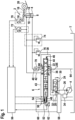
- Modern tractors are equipped with a lifting mechanism 2, which has a double-acting lifting cylinder 4 (also called lifting mechanism cylinder) which is controlled via a valve arrangement 6 according to the invention.
- the lifting cylinder 4 is designed as a differential cylinder with a bottom-side pressure chamber 8 and an annular chamber 10, which can be connected via the valve arrangement 6 to a variable displacement pump 12 or a pressure medium sink, in the present case a tank T.
- the lifting mechanism 2 is designed as a rear lifting mechanism, wherein a piston rod 14 of the lifting cylinder 4 actuates an arm 18 pivotably mounted on a lifting shaft 16 as well as further coupling elements to which, for example, an attachment such as a packer roller 20, a seed drill or a plow is attached.
- the valve arrangement 6 shown for controlling the lifting gear 2 is designed as an LS control with a continuously adjustable directional valve 22 forming a measuring orifice and an LS pressure compensator 24 connected upstream of this.
- an LS control ensures that the pressure in front of the measuring orifice that is controlled in each case is only a certain pressure difference above the individual load pressure, regardless of the pump pressure.
- the invention in no way presupposes such an LS control.
- the pressure connection of the variable displacement pump 12, designed for example as an axial piston pump, is connected via an inlet channel 26 to a pressure connection P' of the pressure compensator 24.
- This is pre-tensioned by a spring 28 into a basic position in which an output connection D of the pressure compensator 24 is blocked.
- the pressure in the inlet channel 26 is tapped via a control channel 30 and guided to a control surface of the pressure compensator 24 which acts in the opening direction, counter to the force of the spring 18.
- the spring 28 and the pressure in an LS channel 32 act in the opposite direction. This is subjected to the pressure downstream of the measuring orifice controlled by the directional valve 22.
- the pressure compensator 24 sets itself in a control position in which the pressure drop across the measuring orifice is kept constant and approximately the same as the Pressure equivalent to the force of the spring 28, so that a constant pressure medium volume flow via the measuring orifice (directional control valve 22) is ensured.
- the delivery pressure of the variable displacement pump 4 in the inlet channel 26 is set in an LS control depending on the highest load pressure applied to the tractor's consumers.
- This load pressure - in the illustrated embodiment, the load pressure on the lifting cylinder 4 - is reported to an LS pressure regulator 34, via which the adjustment of the variable displacement pump is carried out in a manner known per se.
- an LS control in which the delivery flow of the pump is set depending on the highest load pressure, is not a prerequisite for the system according to the invention.
- An output connection D of the pressure compensator 24 is connected to a pressure connection P of the directional control valve 22 via an inlet line 36.
- This also has a return connection T, an LS relief connection LSE and a further pressure connection P', whereby this and the LS relief connection LSE are in pressure medium connection with the LS line 32.
- the LS relief connection LSE is assigned an LS output connection LSR, which in turn is connected to the tank T via an LS return line 43.
- LS pressure relief can be carried out by opening the LS return line.
- the directional control valve 22 also has an output connection P′′′, which is connected via a channel 38 to the pressure connection P' and thus also to the LS line 32.
- a working connection A is connected via a working line 40 to the bottom-side pressure chamber 8 of the lifting cylinder 4.
- Another working connection B is connected via a working line 42 to the annular chamber 10 of the lifting cylinder 4, through which the piston rod 14 passes.
- the adjustment of the directional control valve 22 is carried out via a pilot valve arrangement 50, which in the illustration according to Figure 1 is formed by two electrohydraulic pilot control elements 52, 54.
- the pilot valve arrangement 54 is controlled by means of a control unit 56, which is designed with suitable control software.
- the control oil required to control the pilot valve arrangement 50 is provided via a control oil supply 58, which is connected to the two pilot control elements 52, 54 via a pilot line 60.
- the control oil required to actuate the pilot valve arrangement 50 can be discharged to the tank T via the LS return line 43.
- the position of the slide 44 is detected by a position sensor 62 and reported to the control unit 56, so that the control of the pilot valve arrangement 50 also takes place depending on the signal of the position sensor 62.
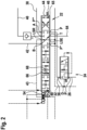
- the slide 44 of the directional control valve 22 is preloaded into a neutral position N via the two centering springs 46, 48, in which the connections P, P", P′′′ and A are blocked.
- the working connection B is connected to the tank connection T, so that the pressure medium can flow from the working line 42 to the tank T via a tank channel 64.
- the LS relief connections LSE and LSR are connected to one another, so that the LS line to the tank T is also relieved.
- a metering orifice 65 connecting the two connections P and P′′′ is opened so that pressure medium can flow from the pressure connection P via the connection P′′′ and the channel 38 to the pressure connection P" and then from there via the working connection A and the working line 40 into the bottom-side pressure chamber 8 of the lifting cylinder 4.
- Its annular space 10 is connected to the tank T via the working line 42, the working connection B, the tank connection T and the tank channel 64 so that the pressure medium can flow out of the shrinking annular space 10.
- the piston of the lifting cylinder 4 extends and the working device is raised or at least supported accordingly.
- valve slide 44 When the valve slide 44 is adjusted from its Figure 2 shown basic position to the right, it is adjusted to a "lowering passive (S passive ) area" in which the connections P, P′′′ and P" are blocked off.
- the two working connections A, B are both connected to the tank connection T.
- the LS pressure relief is also open towards the LS return line 43 so that the attachment, in this case the packer roller 20, is subjected to the lifting cylinder 4 in the retraction direction due to its own weight so that the pressure medium is displaced from the shrinking pressure chamber 8 towards the tank T. From this, pressure medium can flow into the expanding annular space 10.
- the "lowering active (S active ) range” is reached, in which, similar to the lifting range, the two connections P and P′′′ are connected to one another, so that pressure medium is fed from the inlet line 36 via the metering orifice 65 into the channel 38.
- S active range an inlet cross-section 66 between the connections P" and B is opened by a control edge of the slide 44.
- an outlet cross-section 68 is opened via a further control edge, through which the working connection B and thus the annular space 10 effective in the "lowering/pressurizing" direction is connected to the tank T.
- the adjustment of the cross sections 66, 68 preferably takes place in opposite directions.
- a defined pressure drop occurs across this outlet cross-section 68 at a specific slide deflection, whereby this defined pressure drop (“block pressure”) can be varied by varying the slide deflection, i.e. by opening or closing the inlet cross-section 66 or the outlet cross-section 68.
- the inlet cross-section 66 and the outlet cross-section 68 preferably change in opposite directions, so that if the volume flow from the consumer is reduced, the "block pressure" is increased, while if the volume flow to the consumer is reduced, the "block pressure” is reduced.
- a dynamic pressure equilibrium is thus established, which enables a fine pressure adjustment on the lifting cylinder 4 in the "lowering" direction.
- a releasable check valve 70 is provided in the working line 40, which in its closed position prevents pressure medium from flowing out of the pressure chamber 8.
- the check valve 70 is opened mechanically when the slide 44 is adjusted to the "float" and “lower active/passive " ranges. is achieved by mechanically coupling the slide valve 44 to the check valve 70, so that the latter is opened when the slide valve 44 is adjusted into the aforementioned ranges.
- check valve 70 instead of the check valve 70, corresponding check valves can also be integrated into the directional control valve 22. These serve in particular to prevent the attachment/power lift from sinking due to a leak.
- a pressure sensor 72 can be provided, via which the pressure in the annular space 10 or in the working line 42 is recorded and reported to the control unit 56. If the signal from the pressure sensor 72 deviates from the setpoint values, for example due to an inaccurate deflection of the slide 44 or other faults, the slide position can then be corrected in accordance with the control deviation via the control algorithm of the control unit 56.
- the "lowering passive " area can be included in this control in order to only use one control edge opening in the "tank/return" direction without incoming pressure medium. This is necessary, for example, if the attachment has to give way due to a rising ground contour with a constant pressure/ground immersion depth.
- a secondary pressure relief valve 74, 76 can be provided according to the invention, via which the pressure in the working line 42 or the working line 40 is limited, so that the pressure medium releases pressure medium in the direction of the tank T when the pressure set on the pressure relief valve 74, 76 is exceeded. This can be necessary, for example, if the lifting gear 2 has to give way due to a ground contour, so that the pressure relief valve 74 in the working line 42 then opens.
- Another option is to detect the deflection of the lifting cylinder 4 by a position sensor 78.
- This is designed as an angle sensor, which detects the angle of attack of the arm 18. This makes it possible, for example, to calculate the theoretical volume flow on the "pressing side" (alternatively the cylinder speed/hoist speed, which are approximately proportional over large areas). With knowledge of this theoretical volume flow, the following improvements to the system can be achieved, for example.
- the associated advantage is better filling of the lifting cylinder 4, so that the transition to pressure control is continuous.
- a further advantage is that the slide 44 can be deflected further during lowering without building up pressure. This may potentially maximize the single-acting lowering speed, since the control edge determining the discharge cross-section 68 is then completely open.
- a further improvement is that when swerving through a floor contour, the tank drain on the "pressure side" can be opened in a controlled manner depending on the theoretical pressure medium volume flow and the target pressure.
- the advantage of this is that when swerving, even without "closed-loop pressure control", the pressure only increases moderately, or in a system with pressure control, the controller is supported by the pilot control.
- the system can automatically switch to "pressing pressure control” if the volume flow falls below a minimum speed.
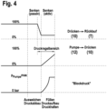
- Figure 3 qualitatively cross-sectional profiles are shown which occur during the adjustment of the slider 44 as described above.
- the areas “lift”, “neutral” and “free travel/float”, in particular their exact start and the gradients, are shown only as examples in this illustration.
- the in Figure 3 The upper cross-section shows the opening cross-section in the previously described adjustment ranges of the slide 44 between the pressure chamber 8 ("carry") and the return (T). Accordingly, this cross-section is controlled open in the two “lowering areas” and is then open in the free passage ("float").
- the opening cross-section of the pump 12 in the direction of the pressure chamber 8 ("carrying") is only opened in the "lifting" range and decreases with increasing adjustment of the slide 44 in the "neutral” direction.
- a defined discharge cross-section 68 is created from the annular space 10 ("pressing") to the Return flow (T). This cross-section is then enlarged again during the transition from the "lowering active " area to the "float” area.
- an inlet cross-section is then opened up in accordance with the above statements, which enables the pressure medium connection between the pump 12 and the annular space 10 and which is then closed again in the free passage ("float") area.
- a valve arrangement and a method for controlling a lifting gear or attachment of a mobile work device are disclosed, wherein a double-acting lifting cylinder is controlled via a directional control valve.
- This is designed with two control edges that simultaneously change an inlet cross-section and an outlet cross-section, so that, for example, a pressure setting on the lifting cylinder in the "lowering" direction is possible.
- the releasable check valve is mechanically coupled to the slide of the directional control valve, so that the check valve can be opened at least when the slide is adjusted to the active lowering range.
Landscapes
- Engineering & Computer Science (AREA)
- Physics & Mathematics (AREA)
- Fluid Mechanics (AREA)
- Mechanical Engineering (AREA)
- General Engineering & Computer Science (AREA)
- Fluid-Pressure Circuits (AREA)
Claims (10)
- Agencement de vanne pour la commande d'un mécanisme de levage (2) ou d'un outil porté d'un appareil de travail mobile, en particulier d'un véhicule utilitaire agricole, le mécanisme de levage ou l'outil porté présentant un vérin de levage (4),
l'agencement de vanne comprenant un distributeur (22) réglable en continu, qui présente un raccord de travail (A) apte à être mis en communication de fluide sous pression avec une chambre de pression (8) du vérin de levage (4), qui agit dans une première direction d'actionnement, et qui présente un autre raccord de travail (B) apte à être mis en communication de fluide sous pression avec une deuxième chambre de pression (10) du vérin de levage (4), qui agit dans une deuxième direction d'actionnement, le distributeur (22) ayant un raccord de réservoir (T) et un raccord de pression (P), des sections transversales d'ouverture entre les raccords étant aptes à être commandées en ouverture ou en fermeture par déplacement d'un tiroir (44) du distributeur (22), le tiroir (44) ayant deux arêtes de commande d'abaissement actif, par l'intermédiaire desquelles, lors du déplacement du tiroir (44) dans une plage d'abaissement actif (Senkenaktiv), une section transversale d'entrée (66) est apte à être commandée en direction de la chambre de pression (10) qui agit dans la deuxième direction d'actionnement et, simultanément, une section transversale de sortie (68) est apte à être commandée en ouverture ou en fermeture depuis la chambre de pression (10) qui agit dans la deuxième direction d'actionnement, en direction du raccord de réservoir (T), de préférence en sens inverse, caractérisé par au moins un clapet anti-retour (70) déblocable, agencé dans un chemin d'écoulement de fluide sous pression, vers la chambre de pression (8) qui agit dans la première direction d'actionnement, depuis le raccord de travail apte à être relié à celle-ci, lequel est relié mécaniquement au tiroir (44), de sorte que le clapet anti-retour (70) est apte à être commandé en ouverture au moins lors d'un déplacement du tiroir (44) dans la plage d'abaissement actif (Senkenaktiv). - Agencement de vanne selon la revendication 1, dans lequel le distributeur (22) a une plage de réglage de tiroir, une position flottante et/ou un abaissement neutre et/ou passif (Senkenpassiv) et/ou un levage.
- Agencement de vanne selon la revendication 2, dans lequel la plage de réglage de tiroir d'abaissement actif (Senkenaktiv) est voisine de la plage de réglage de tiroir d'abaissement passif (Senkenpassiv).
- Agencement de vanne selon l'une des revendications précédentes, dans lequel un compensateur de pression LS (24) est prévu à l'entrée du distributeur (22).
- Agencement de vanne selon l'une des revendications précédentes, comprenant une vanne de limitation de pression (74, 76) dans un chemin d'écoulement de fluide sous pression entre un raccord de travail (A, B) et la chambre de pression (8, 10) qui y est reliée.
- Agencement de vanne selon l'une des revendications précédentes, comprenant un capteur de position (78) pour détecter une position du mécanisme de levage/de l'outil porté.
- Agencement de vanne selon l'une des revendications précédentes, comprenant un capteur de pression (72) dans un chemin d'écoulement de fluide sous pression vers l'une des chambres de pression (8, 10) à partir du raccord de travail (A, B) apte à être relié à celle-ci.
- Agencement de vanne selon la revendication 6 ou la revendication 7, comprenant une unité de commande (56) qui est conçue, de préférence à la manière d'une régulation en boucle fermée, pour régler/corriger la position du tiroir en fonction du signal de pression du capteur de pression (72) et/ou en fonction du signal du capteur de position (76).
- Agencement de vanne selon l'une des revendications précédentes, dans lequel le distributeur (22) est commandé de manière électrohydraulique.
- Procédé de commande d'un mécanisme de levage ou d'un outil porté d'un appareil de travail mobile, en particulier d'un véhicule utilitaire agricole, le mécanisme de levage ou l'outil porté présentant un vérin de levage (4),le procédé présentant un distributeur (22) réglable en continu, qui a un raccord de travail (A), qui est en liaison de fluide sous pression avec une chambre de pression (8) du vérin de levage (4), qui agit dans une première direction d'actionnement, et qui a un autre raccord de travail (B), qui est en liaison de fluide sous pression avec une deuxième chambre de pression (10) du vérin de levage (4), qui agit dans une deuxième direction d'actionnement, le distributeur (22) ayant en outre un raccord de réservoir (T) et un raccord de pression (P), des sections transversales d'ouverture entre les raccords étant aptes à être commandées en ouverture ou en fermeture en déplaçant un tiroir (44) du distributeur (22),et le procédé comprenant les étapes suivantes :- réglage du tiroir (44) dans une plage de réglage d'abaissement actif (Senkenaktiv), dans laquelle- une section transversale d'entrée (66) est commandée vers la chambre de pression (10) qui agit dans la deuxième direction d'actionnement par l'intermédiaire d'une première arête de commande d'abaissement actif, et, simultanément ou en chevauchement, une section transversale de sortie (68) est commandée vers ou depuis la chambre de pression (10) qui agit dans la deuxième direction d'actionnement vers le réservoir (T) par l'intermédiaire d'une deuxième arête de commande d'abaissement actif, de sorte qu'il s'établit un équilibre de pression dynamique, et- commande d'au moins un clapet anti-retour (70) déblocable, agencé dans un chemin d'écoulement de fluide sous pression, vers la chambre de pression (8) qui agit dans la première direction d'actionnement, depuis le raccord de travail qui y est relié, lequel est relié mécaniquement au tiroir (44), lors du déplacement du tiroir (44) dans la plage de réglage d'abaissement actif (Senkenaktiv).
Applications Claiming Priority (1)
| Application Number | Priority Date | Filing Date | Title |
|---|---|---|---|
| DE102020208922.1A DE102020208922B3 (de) | 2020-07-16 | 2020-07-16 | Ventilanordnung |
Publications (2)
| Publication Number | Publication Date |
|---|---|
| EP3940246A1 EP3940246A1 (fr) | 2022-01-19 |
| EP3940246B1 true EP3940246B1 (fr) | 2025-02-26 |
Family
ID=76890864
Family Applications (1)
| Application Number | Title | Priority Date | Filing Date |
|---|---|---|---|
| EP21185034.2A Active EP3940246B1 (fr) | 2020-07-16 | 2021-07-12 | Agencement de soupape et procédé pour commander un dispositif de levage ou un appareil porté |
Country Status (2)
| Country | Link |
|---|---|
| EP (1) | EP3940246B1 (fr) |
| DE (1) | DE102020208922B3 (fr) |
Families Citing this family (3)
| Publication number | Priority date | Publication date | Assignee | Title |
|---|---|---|---|---|
| DE102022202288A1 (de) | 2022-03-08 | 2023-09-14 | Robert Bosch Gesellschaft mit beschränkter Haftung | Arbeitsvorrichtung mit einem Ventil, welches wenigstens eine gesonderte Entleerstellung hat |
| DE102022211400A1 (de) | 2022-10-27 | 2024-05-02 | Robert Bosch Gesellschaft mit beschränkter Haftung | Verfahren zum Betreiben eines hydraulischen Antriebssystems |
| CN115407647B (zh) * | 2022-10-31 | 2023-01-24 | 艾坦姆流体控制技术(山东)有限公司 | 一种优化控制方法及使用该方法的三级打孔阀控制系统 |
Family Cites Families (10)
| Publication number | Priority date | Publication date | Assignee | Title |
|---|---|---|---|---|
| DE19510331A1 (de) * | 1994-03-29 | 1995-10-05 | Bucher Gmbh | Ansteuerung für ein Wegeventil in einem hydraulischen Antriebssystem |
| DE10138389A1 (de) | 2001-08-04 | 2003-02-20 | Bosch Gmbh Robert | Elektrohydraulische Einrichtung zur Steuerung eines doppelt wirkenden Motors |
| DE102004033315A1 (de) | 2004-07-09 | 2006-02-09 | Bosch Rexroth Aktiengesellschaft | Hubwerksventilanordnung |
| DE102006004423B4 (de) | 2006-01-31 | 2018-08-02 | Robert Bosch Gmbh | Ventilanordnung zur Ansteuerung eines Hubwerkes oder Anbaugerätes sowie Verfahren zur Ansteuerung dieser |
| DE102007057655A1 (de) * | 2007-11-28 | 2009-06-04 | Robert Bosch Gmbh | Fahrantrieb für Arbeitsgeräte |
| EP2597210B1 (fr) | 2011-11-23 | 2016-03-16 | HAWE Hydraulik SE | Dispositif de commande hydroélectrique |
| DE102013207299B4 (de) | 2013-04-23 | 2025-11-06 | Robert Bosch Gmbh | Hydraulisches Wegeventil für das Hubwerk eines landwirtschaftlichen Fahrzeugs |
| GB201319154D0 (en) | 2013-10-30 | 2013-12-11 | Agco Int Gmbh | Hydraulic system supply |
| US10321621B2 (en) | 2016-08-11 | 2019-06-18 | Deere & Company | Electronic latching circuit |
| DE102017219942A1 (de) | 2017-11-09 | 2019-05-09 | Robert Bosch Gmbh | Ventilanordung für Hubwerkssteuerung mit einer Druckregelvorrichtung |
-
2020
- 2020-07-16 DE DE102020208922.1A patent/DE102020208922B3/de active Active
-
2021
- 2021-07-12 EP EP21185034.2A patent/EP3940246B1/fr active Active
Also Published As
| Publication number | Publication date |
|---|---|
| EP3940246A1 (fr) | 2022-01-19 |
| DE102020208922B3 (de) | 2021-12-09 |
Similar Documents
| Publication | Publication Date | Title |
|---|---|---|
| EP2541072B1 (fr) | Agencement de commande et procédé de commande de plusieurs consommateurs hydrauliques | |
| EP2031256B1 (fr) | Dispositif de levage et procédé de commande d'un dispositif de levage | |
| DE60105849T2 (de) | Hydraulisches wegeventilsystem mit druckwaagen | |
| EP1092095B2 (fr) | Circuit hydraulique | |
| EP2225470B1 (fr) | Système de distributeur | |
| EP2524585B1 (fr) | Dispositif de levage | |
| EP1766146B2 (fr) | Systeme de soupapes de mecanisme de levage | |
| DE69110319T2 (de) | Hydraulisch angetriebenes System. | |
| DE102020206343A1 (de) | Verfahren zur Kalibrierung eines elektroproportional verstellbaren Stetigventils | |
| EP1281872B1 (fr) | Dispositif electro-hydraulique pour le contrôle d'un moteur à double effet | |
| EP3940246A1 (fr) | Agencement de soupape et procédé pour commander un dispositif de levage ou un appareil porté | |
| EP1672225B1 (fr) | Assemblage de vannes et méthode de contrôle d'un consommateur hydraulique à double effet | |
| DE69727552T2 (de) | Hydraulisches antriebssystem | |
| EP2142808B1 (fr) | Ensemble de commande hydraulique | |
| EP2404493B1 (fr) | Dispositif de levage | |
| EP2542788B1 (fr) | Dispositif de commande hydraulique | |
| DE2601999A1 (de) | Anordnung zur beeinflussung der arbeitsmenge eines servomotors | |
| DE102006004423B4 (de) | Ventilanordnung zur Ansteuerung eines Hubwerkes oder Anbaugerätes sowie Verfahren zur Ansteuerung dieser | |
| EP3135924B1 (fr) | Commande hydraulique | |
| EP1643138B1 (fr) | Commande hydraulique | |
| EP3530962B1 (fr) | Procédé de commande d'une pression de descente d'un levage assisté électrohydraulique et levage électrohydraulique | |
| EP1766246B1 (fr) | Procede de commande d'un systeme a vannes pour dispositif de levage | |
| EP3985264A1 (fr) | Agencement et procédé de commande d'un mécanisme de levage | |
| DE102023204654B4 (de) | Ventilbaugruppe zur Betätigung eines Hubwerks | |
| DE102018204568A1 (de) | Verfahren zur Steuerung eines Senkendrucks eines elektrohydraulischen Krafthebers und elektrohydraulischer Kraftheber |
Legal Events
| Date | Code | Title | Description |
|---|---|---|---|
| PUAI | Public reference made under article 153(3) epc to a published international application that has entered the european phase |
Free format text: ORIGINAL CODE: 0009012 |
|
| STAA | Information on the status of an ep patent application or granted ep patent |
Free format text: STATUS: THE APPLICATION HAS BEEN PUBLISHED |
|
| AK | Designated contracting states |
Kind code of ref document: A1 Designated state(s): AL AT BE BG CH CY CZ DE DK EE ES FI FR GB GR HR HU IE IS IT LI LT LU LV MC MK MT NL NO PL PT RO RS SE SI SK SM TR |
|
| STAA | Information on the status of an ep patent application or granted ep patent |
Free format text: STATUS: REQUEST FOR EXAMINATION WAS MADE |
|
| 17P | Request for examination filed |
Effective date: 20220719 |
|
| RBV | Designated contracting states (corrected) |
Designated state(s): AL AT BE BG CH CY CZ DE DK EE ES FI FR GB GR HR HU IE IS IT LI LT LU LV MC MK MT NL NO PL PT RO RS SE SI SK SM TR |
|
| GRAP | Despatch of communication of intention to grant a patent |
Free format text: ORIGINAL CODE: EPIDOSNIGR1 |
|
| STAA | Information on the status of an ep patent application or granted ep patent |
Free format text: STATUS: GRANT OF PATENT IS INTENDED |
|
| INTG | Intention to grant announced |
Effective date: 20241202 |
|
| GRAS | Grant fee paid |
Free format text: ORIGINAL CODE: EPIDOSNIGR3 |
|
| GRAA | (expected) grant |
Free format text: ORIGINAL CODE: 0009210 |
|
| STAA | Information on the status of an ep patent application or granted ep patent |
Free format text: STATUS: THE PATENT HAS BEEN GRANTED |
|
| AK | Designated contracting states |
Kind code of ref document: B1 Designated state(s): AL AT BE BG CH CY CZ DE DK EE ES FI FR GB GR HR HU IE IS IT LI LT LU LV MC MK MT NL NO PL PT RO RS SE SI SK SM TR |
|
| REG | Reference to a national code |
Ref country code: GB Ref legal event code: FG4D Free format text: NOT ENGLISH |
|
| REG | Reference to a national code |
Ref country code: CH Ref legal event code: EP |
|
| REG | Reference to a national code |
Ref country code: DE Ref legal event code: R096 Ref document number: 502021006759 Country of ref document: DE |
|
| REG | Reference to a national code |
Ref country code: IE Ref legal event code: FG4D Free format text: LANGUAGE OF EP DOCUMENT: GERMAN |
|
| REG | Reference to a national code |
Ref country code: NL Ref legal event code: MP Effective date: 20250226 |
|
| PG25 | Lapsed in a contracting state [announced via postgrant information from national office to epo] |
Ref country code: RS Free format text: LAPSE BECAUSE OF FAILURE TO SUBMIT A TRANSLATION OF THE DESCRIPTION OR TO PAY THE FEE WITHIN THE PRESCRIBED TIME-LIMIT Effective date: 20250526 |
|
| PG25 | Lapsed in a contracting state [announced via postgrant information from national office to epo] |
Ref country code: FI Free format text: LAPSE BECAUSE OF FAILURE TO SUBMIT A TRANSLATION OF THE DESCRIPTION OR TO PAY THE FEE WITHIN THE PRESCRIBED TIME-LIMIT Effective date: 20250226 |
|
| PG25 | Lapsed in a contracting state [announced via postgrant information from national office to epo] |
Ref country code: PL Free format text: LAPSE BECAUSE OF FAILURE TO SUBMIT A TRANSLATION OF THE DESCRIPTION OR TO PAY THE FEE WITHIN THE PRESCRIBED TIME-LIMIT Effective date: 20250226 |
|
| PG25 | Lapsed in a contracting state [announced via postgrant information from national office to epo] |
Ref country code: ES Free format text: LAPSE BECAUSE OF FAILURE TO SUBMIT A TRANSLATION OF THE DESCRIPTION OR TO PAY THE FEE WITHIN THE PRESCRIBED TIME-LIMIT Effective date: 20250226 |
|
| REG | Reference to a national code |
Ref country code: LT Ref legal event code: MG9D |
|
| PG25 | Lapsed in a contracting state [announced via postgrant information from national office to epo] |
Ref country code: NO Free format text: LAPSE BECAUSE OF FAILURE TO SUBMIT A TRANSLATION OF THE DESCRIPTION OR TO PAY THE FEE WITHIN THE PRESCRIBED TIME-LIMIT Effective date: 20250526 Ref country code: IS Free format text: LAPSE BECAUSE OF FAILURE TO SUBMIT A TRANSLATION OF THE DESCRIPTION OR TO PAY THE FEE WITHIN THE PRESCRIBED TIME-LIMIT Effective date: 20250626 |
|
| PG25 | Lapsed in a contracting state [announced via postgrant information from national office to epo] |
Ref country code: NL Free format text: LAPSE BECAUSE OF FAILURE TO SUBMIT A TRANSLATION OF THE DESCRIPTION OR TO PAY THE FEE WITHIN THE PRESCRIBED TIME-LIMIT Effective date: 20250226 |
|
| PG25 | Lapsed in a contracting state [announced via postgrant information from national office to epo] |
Ref country code: HR Free format text: LAPSE BECAUSE OF FAILURE TO SUBMIT A TRANSLATION OF THE DESCRIPTION OR TO PAY THE FEE WITHIN THE PRESCRIBED TIME-LIMIT Effective date: 20250226 |
|
| PG25 | Lapsed in a contracting state [announced via postgrant information from national office to epo] |
Ref country code: PT Free format text: LAPSE BECAUSE OF FAILURE TO SUBMIT A TRANSLATION OF THE DESCRIPTION OR TO PAY THE FEE WITHIN THE PRESCRIBED TIME-LIMIT Effective date: 20250626 Ref country code: LV Free format text: LAPSE BECAUSE OF FAILURE TO SUBMIT A TRANSLATION OF THE DESCRIPTION OR TO PAY THE FEE WITHIN THE PRESCRIBED TIME-LIMIT Effective date: 20250226 |
|
| PG25 | Lapsed in a contracting state [announced via postgrant information from national office to epo] |
Ref country code: BG Free format text: LAPSE BECAUSE OF FAILURE TO SUBMIT A TRANSLATION OF THE DESCRIPTION OR TO PAY THE FEE WITHIN THE PRESCRIBED TIME-LIMIT Effective date: 20250226 Ref country code: GR Free format text: LAPSE BECAUSE OF FAILURE TO SUBMIT A TRANSLATION OF THE DESCRIPTION OR TO PAY THE FEE WITHIN THE PRESCRIBED TIME-LIMIT Effective date: 20250527 |
|
| PG25 | Lapsed in a contracting state [announced via postgrant information from national office to epo] |
Ref country code: SE Free format text: LAPSE BECAUSE OF FAILURE TO SUBMIT A TRANSLATION OF THE DESCRIPTION OR TO PAY THE FEE WITHIN THE PRESCRIBED TIME-LIMIT Effective date: 20250226 |
|
| PG25 | Lapsed in a contracting state [announced via postgrant information from national office to epo] |
Ref country code: SM Free format text: LAPSE BECAUSE OF FAILURE TO SUBMIT A TRANSLATION OF THE DESCRIPTION OR TO PAY THE FEE WITHIN THE PRESCRIBED TIME-LIMIT Effective date: 20250226 |
|
| PG25 | Lapsed in a contracting state [announced via postgrant information from national office to epo] |
Ref country code: DK Free format text: LAPSE BECAUSE OF FAILURE TO SUBMIT A TRANSLATION OF THE DESCRIPTION OR TO PAY THE FEE WITHIN THE PRESCRIBED TIME-LIMIT Effective date: 20250226 |
|
| PGFP | Annual fee paid to national office [announced via postgrant information from national office to epo] |
Ref country code: DE Payment date: 20250924 Year of fee payment: 5 |
|
| PGFP | Annual fee paid to national office [announced via postgrant information from national office to epo] |
Ref country code: IT Payment date: 20250731 Year of fee payment: 5 |
|
| PGFP | Annual fee paid to national office [announced via postgrant information from national office to epo] |
Ref country code: AT Payment date: 20251020 Year of fee payment: 5 Ref country code: FR Payment date: 20250723 Year of fee payment: 5 |
|
| PG25 | Lapsed in a contracting state [announced via postgrant information from national office to epo] |
Ref country code: CZ Free format text: LAPSE BECAUSE OF FAILURE TO SUBMIT A TRANSLATION OF THE DESCRIPTION OR TO PAY THE FEE WITHIN THE PRESCRIBED TIME-LIMIT Effective date: 20250226 Ref country code: EE Free format text: LAPSE BECAUSE OF FAILURE TO SUBMIT A TRANSLATION OF THE DESCRIPTION OR TO PAY THE FEE WITHIN THE PRESCRIBED TIME-LIMIT Effective date: 20250226 |
|
| PG25 | Lapsed in a contracting state [announced via postgrant information from national office to epo] |
Ref country code: RO Free format text: LAPSE BECAUSE OF FAILURE TO SUBMIT A TRANSLATION OF THE DESCRIPTION OR TO PAY THE FEE WITHIN THE PRESCRIBED TIME-LIMIT Effective date: 20250226 |
|
| PG25 | Lapsed in a contracting state [announced via postgrant information from national office to epo] |
Ref country code: SK Free format text: LAPSE BECAUSE OF FAILURE TO SUBMIT A TRANSLATION OF THE DESCRIPTION OR TO PAY THE FEE WITHIN THE PRESCRIBED TIME-LIMIT Effective date: 20250226 |
|
| REG | Reference to a national code |
Ref country code: DE Ref legal event code: R097 Ref document number: 502021006759 Country of ref document: DE |
|
| PLBE | No opposition filed within time limit |
Free format text: ORIGINAL CODE: 0009261 |
|
| STAA | Information on the status of an ep patent application or granted ep patent |
Free format text: STATUS: NO OPPOSITION FILED WITHIN TIME LIMIT |
|
| REG | Reference to a national code |
Ref country code: CH Ref legal event code: L10 Free format text: ST27 STATUS EVENT CODE: U-0-0-L10-L00 (AS PROVIDED BY THE NATIONAL OFFICE) Effective date: 20260107 |
|
| 26N | No opposition filed |
Effective date: 20251127 |
|
| REG | Reference to a national code |
Ref country code: CH Ref legal event code: H13 Free format text: ST27 STATUS EVENT CODE: U-0-0-H10-H13 (AS PROVIDED BY THE NATIONAL OFFICE) Effective date: 20260224 |
|
| PG25 | Lapsed in a contracting state [announced via postgrant information from national office to epo] |
Ref country code: LU Free format text: LAPSE BECAUSE OF NON-PAYMENT OF DUE FEES Effective date: 20250712 |
|
| GBPC | Gb: european patent ceased through non-payment of renewal fee |
Effective date: 20250712 |
|
| REG | Reference to a national code |
Ref country code: BE Ref legal event code: MM Effective date: 20250731 |
|
| PG25 | Lapsed in a contracting state [announced via postgrant information from national office to epo] |
Ref country code: GB Free format text: LAPSE BECAUSE OF NON-PAYMENT OF DUE FEES Effective date: 20250712 |
|
| PG25 | Lapsed in a contracting state [announced via postgrant information from national office to epo] |
Ref country code: BE Free format text: LAPSE BECAUSE OF NON-PAYMENT OF DUE FEES Effective date: 20250731 |
|
| PG25 | Lapsed in a contracting state [announced via postgrant information from national office to epo] |
Ref country code: CH Free format text: LAPSE BECAUSE OF NON-PAYMENT OF DUE FEES Effective date: 20250731 |