EP3940904A1 - Dispositif d'étanchéité - Google Patents
Dispositif d'étanchéité Download PDFInfo
- Publication number
- EP3940904A1 EP3940904A1 EP21191260.5A EP21191260A EP3940904A1 EP 3940904 A1 EP3940904 A1 EP 3940904A1 EP 21191260 A EP21191260 A EP 21191260A EP 3940904 A1 EP3940904 A1 EP 3940904A1
- Authority
- EP
- European Patent Office
- Prior art keywords
- sealing
- section
- sealing device
- unit
- sealing unit
- Prior art date
- Legal status (The legal status is an assumption and is not a legal conclusion. Google has not performed a legal analysis and makes no representation as to the accuracy of the status listed.)
- Withdrawn
Links
- 238000007789 sealing Methods 0.000 claims abstract description 355
- 238000003780 insertion Methods 0.000 claims description 73
- 230000037431 insertion Effects 0.000 claims description 73
- 230000000087 stabilizing effect Effects 0.000 claims description 48
- 238000000034 method Methods 0.000 claims description 25
- 239000000463 material Substances 0.000 claims description 23
- 238000001746 injection moulding Methods 0.000 claims description 7
- 230000006641 stabilisation Effects 0.000 description 28
- 238000011105 stabilization Methods 0.000 description 28
- 238000004519 manufacturing process Methods 0.000 description 6
- 230000000295 complement effect Effects 0.000 description 5
- 230000000694 effects Effects 0.000 description 5
- 230000000712 assembly Effects 0.000 description 3
- 238000000429 assembly Methods 0.000 description 3
- 239000007788 liquid Substances 0.000 description 3
- 238000010276 construction Methods 0.000 description 2
- 229920001971 elastomer Polymers 0.000 description 2
- 229920002635 polyurethane Polymers 0.000 description 2
- 239000004814 polyurethane Substances 0.000 description 2
- 239000007787 solid Substances 0.000 description 2
- 229920001169 thermoplastic Polymers 0.000 description 2
- 239000004416 thermosoftening plastic Substances 0.000 description 2
- 241000237942 Conidae Species 0.000 description 1
- 229920000459 Nitrile rubber Polymers 0.000 description 1
- 239000000853 adhesive Substances 0.000 description 1
- 230000001070 adhesive effect Effects 0.000 description 1
- 238000007664 blowing Methods 0.000 description 1
- 239000002131 composite material Substances 0.000 description 1
- 230000006835 compression Effects 0.000 description 1
- 238000007906 compression Methods 0.000 description 1
- 230000001419 dependent effect Effects 0.000 description 1
- 238000011161 development Methods 0.000 description 1
- 230000018109 developmental process Effects 0.000 description 1
- 239000000806 elastomer Substances 0.000 description 1
- 230000007613 environmental effect Effects 0.000 description 1
- 239000003365 glass fiber Substances 0.000 description 1
- 238000003475 lamination Methods 0.000 description 1
- 239000011159 matrix material Substances 0.000 description 1
- 239000007769 metal material Substances 0.000 description 1
- 239000002245 particle Substances 0.000 description 1
- 230000035515 penetration Effects 0.000 description 1
- 239000004033 plastic Substances 0.000 description 1
- 229920003023 plastic Polymers 0.000 description 1
- 229920001084 poly(chloroprene) Polymers 0.000 description 1
- 238000003825 pressing Methods 0.000 description 1
- 238000007639 printing Methods 0.000 description 1
- 230000001681 protective effect Effects 0.000 description 1
- 230000002441 reversible effect Effects 0.000 description 1
- 239000005060 rubber Substances 0.000 description 1
- 238000010008 shearing Methods 0.000 description 1
- 238000005507 spraying Methods 0.000 description 1
- -1 styrene ethylene butylene styrene Chemical class 0.000 description 1
- 239000012815 thermoplastic material Substances 0.000 description 1
- 230000007704 transition Effects 0.000 description 1
- 238000003466 welding Methods 0.000 description 1
Images




Classifications
-
- H—ELECTRICITY
- H02—GENERATION; CONVERSION OR DISTRIBUTION OF ELECTRIC POWER
- H02G—INSTALLATION OF ELECTRIC CABLES OR LINES, OR OF COMBINED OPTICAL AND ELECTRIC CABLES OR LINES
- H02G15/00—Cable fittings
- H02G15/013—Sealing means for cable inlets
-
- H—ELECTRICITY
- H02—GENERATION; CONVERSION OR DISTRIBUTION OF ELECTRIC POWER
- H02G—INSTALLATION OF ELECTRIC CABLES OR LINES, OR OF COMBINED OPTICAL AND ELECTRIC CABLES OR LINES
- H02G3/00—Installations of electric cables or lines or protective tubing therefor in or on buildings, equivalent structures or vehicles
- H02G3/02—Details
- H02G3/08—Distribution boxes; Connection or junction boxes
- H02G3/081—Bases, casings or covers
- H02G3/083—Inlets
- H02G3/085—Inlets including knock-out or tear-out sections
-
- H—ELECTRICITY
- H02—GENERATION; CONVERSION OR DISTRIBUTION OF ELECTRIC POWER
- H02G—INSTALLATION OF ELECTRIC CABLES OR LINES, OR OF COMBINED OPTICAL AND ELECTRIC CABLES OR LINES
- H02G3/00—Installations of electric cables or lines or protective tubing therefor in or on buildings, equivalent structures or vehicles
- H02G3/22—Installations of cables or lines through walls, floors or ceilings, e.g. into buildings
Definitions
- the invention relates to a sealing device according to the preamble of claim 1 and a method for sealing at least one elongate object relative to a sealing panel according to the preamble of claim 15.
- a sealing device with a sealing unit which has a sealing element with stepped areas with different diameters and a through-opening for the passage of a cable.
- the sealing unit is formed from a thermoplastic such as styrene ethylene butylene styrene (SEBS) or an elastomer such as nitrile butadiene rubber.
- SEBS styrene ethylene butylene styrene
- the sealing unit is fastened with its base body to a frame element consisting of two frame parts by means of a press fit.
- EP 1 643 604 A1 a gel body with a gel mass and a skin arranged on a top and bottom side of the gel mass, the skin being firmly connected to the gel mass.
- the skin is intended to contribute to emergence and/or dragging of the gel mass to prevent an elongate object from being pierced through the skin and the gel mass via the top and bottom of the gel mass.
- a spout acting as a sealing unit for passing through an elongate object is known, the ends of which are designed in the form of a truncated cone shell with respect to a main extension direction of the sealing unit.
- the object of the invention consists in particular in providing a generic sealing device with improved properties with regard to assembly.
- the object is achieved according to the invention by the features of claims 1 and 15, while advantageous configurations and developments of the invention can be found in the dependent claims.
- the invention is based on a sealing device for passing through and sealing an elongate object, with at least one sealing unit which is intended to completely enclose the object in the circumferential direction at least in sections in an assembled state, and which has at least one sealing section which is intended for this purpose , to contact the object in the mounted state and to seal it by means of an intrinsic prestress.
- the sealing section has an at least essentially constant inner diameter (18a, 18b, 18c, 18d, 18e) over at least a large part of its length in at least one dismantled state.
- assembly can advantageously be simplified.
- a time-saving assembly process can advantageously be made possible.
- a low-cost configuration can be achieved.
- a simplification of assembly can be achieved due to an advantageous construction.
- a “sealing device” should be understood in particular as a part of a sealing system, in particular a cable sleeve, which is intended in particular to protect cable contacting points from environmental influences.
- the sealing system preferably comprises the sealing device and at least one housing, particularly advantageously a sleeve hood, with a sealing panel, in particular a sleeve base, on which the sealing device can be arranged.
- the sealing device can be provided for the passage and sealing of more than just a single elongate object, in particular at least two elongate objects.
- an “elongated object” is to be understood in particular as an object which, in at least one unwound state, has an extension along a main extension direction which has at least twice, advantageously at least three times, preferably at least five times the diameter of the object, which in particular is transverse to the Main extension direction is measured.
- the elongate object can be designed as a tube, in particular as a blowing tube and/or preferably as a cable, in particular as an electrical cable and/or particularly advantageously as a glass fiber cable.
- a "main extension direction" of an object is to be understood in particular as a direction which runs parallel to a longest edge of the smallest imaginary cuboid which just about completely encloses the object.
- a “sealing unit” is to be understood in particular as a unit which allows matter to penetrate from a first area into a second area and vice versa and/or an exchange between matter from the first and the second area, between which the sealing unit is at least partially arranged , at least essentially completely prevented.
- the sealing unit has a protective effect against the ingress of moisture and/or liquid.
- “at least substantially fully” is meant here In particular, it should be understood that penetration of matter from the first into the second space and vice versa is below a leak rate that is suitable for the intended purpose and is in particular specified by law and/or by guidelines.
- the sealing unit has at least one, preferably precisely one, feed-through channel for the object.
- the sealing unit can advantageously have two, three or, in particular, a plurality of lead-through channels, each for one object.
- the lead-through channel is intended in particular to accommodate the object.
- the feedthrough channel has a variable feedthrough channel diameter over its length.
- the feedthrough channel has a length which is at least as great, in particular at least twice as great, advantageously at least three times as great as the maximum feedthrough passage diameter.
- the lead-through channel has a length of at least 20 mm, advantageously at least 30 mm and preferably at least 35 mm.
- the maximum feedthrough channel diameter is at least 5 mm, advantageously at least 8 mm and particularly advantageously at least 10 mm.
- a diameter of the sealing unit has a variable size when viewed over a length of the sealing unit.
- a maximum diameter of the sealing unit is at least equal to the maximum through-channel diameter, preferably at least equal to 1.5 times the maximum through-channel diameter and/or preferably at least equal to 1.9 times the maximum through-channel diameter.
- the maximum diameter of the sealing unit has a value between 18 mm and 22 mm.
- a “sealing section” is to be understood in particular as a part of the sealing unit which, in an assembled state, is intended to exert a sealing effect.
- the sealing section is in particular in the form of a hollow cylinder with an outer and an inner diameter and with an outer and an inner surface.
- the lead-through channel for the object runs at least partially through the sealing section.
- An "assembled state” is to be understood in particular as a state of a unit in which individual components of the unit are assembled and/or connected to one another in such a way that the unit can fulfill and/or perform at least one function assigned to it and at the same time one intended for the unit Can exert an effect on another unit, in particular the unit contacts the other unit.
- the sealing unit develops a sealing effect on the object in the mounted state, with the object being inserted into the sealing unit.
- the sealing section consists at least partially and preferably entirely of a colloidal material.
- a “colloid-like material” is to be understood in particular as meaning a material which has at least one solid and at least one liquid and/or gaseous component.
- the solid component is designed as a spongy three-dimensional matrix in which the liquid and/or gaseous component is distributed.
- the colloid-like material is preferably at least partially and preferably completely formed as a gel, preferably as a polyurethane gel.
- the colloidal material is dimensionally stable under standard conditions, the material undergoing a reversible change in shape at least under a small, in particular mechanical, load and then, in the absence of the load, assuming its original shape.
- the material has elastic properties.
- the colloidal material is in particular reversibly deformable, taking on a shape that existed prior to deformation.
- the colloidal material can change its extent, in particular in several dimensions, with a change in length of the shape of the colloidal material being accompanied by a change in width of the shape of the colloidal material.
- An "intrinsic pretension” is to be understood in particular as a property of a unit in which the unit unfolds a self-sealing function when it comes into contact with a further unit to be sealed, without assistance of other units.
- Provided should be understood to mean, in particular, specially programmed, designed and/or equipped.
- the fact that an object is provided for a specific function is to be understood in particular to mean that the object fulfills and/or executes this specific function in at least one application and/or operating state.
- the sealing unit has at least one further sealing section, which is provided in the installed state to contact a further elongate object that is different from the elongate object and to seal it by means of an intrinsic prestress.
- a plurality of elongate objects can advantageously be sealed independently of one another.
- the sealing unit has a multiplicity of further sealing sections, each of which passes through and seals an elongate object.
- the sealing section and the further sealing section/s are arranged next to one another.
- the sealing section and the further sealing section/the further sealing sections are advantageously of identical design and advantageously have identical properties.
- the sealing section and the additional sealing section/the additional sealing sections can be designed differently.
- the further sealing section consists at least partially and preferably completely of a colloidal material.
- the sealing section and/or the further sealing section lies tightly against the elongate object over its entire length when the sealing unit is mounted on the elongate object.
- the sealing section and/or the further sealing section exerts a radially inwardly directed pressure on the elongate object in a mounted state. In the installed state, the pressure is advantageously permanently applied over the entire length of the sealing section and/or the further sealing sections.
- a “disassembled state” is intended to mean, in particular, a state of a unit be understood, in which the unit is ineffective and / or functionless in particular compared to another unit and / or the unit and the other unit are contactless.
- the sealing section and/or the further sealing section have an at least essentially constant outer diameter in at least one dismantled state over at least a large part of its length.
- a uniform sealing effect on the elongate object can be achieved in the assembled state, preferably at each contact point between the sealing section and/or the further sealing section and the elongate object in the assembled state.
- the outer diameter of the sealing section and/or the further sealing section is greater than the length of the sealing section and/or the further sealing section.
- the sealing unit has at least one cable insertion section for inserting the object.
- the sealing unit can advantageously have two, in particular multiple, cable insertion sections, each for inserting an object.
- an insertion aid can be provided for a technician during assembly, as a result of which a time saving can be achieved.
- this can advantageously increase process reliability during assembly.
- the cable insertion section/the cable insertion sections and the sealing section and/or the further sealing section are connected to one another in one piece.
- In one piece is to be understood in particular as being at least cohesively connected, for example by a welding process, an adhesive process, a spraying process and/or another process that appears sensible to the person skilled in the art, and/or advantageously formed in one piece, such as by a Manufacture from a single cast and/or by manufacture in a one-component or multi-component injection molding process and/or by manufacture in a pressure process and advantageously from a single blank.
- the cable insertion section/cable insertion sections is/are in particular as a hollow body educated. In particular, the cable insertion section(s) has/have a different outer and/or inner diameter along its/their respective main extension direction.
- the cable insertion section(s) has/have a larger average outer and/or inner diameter than an outer and/or inner diameter of the sealing section and/or the further sealing sections.
- the cable insertion section/sections each have a larger inner diameter compared to a diameter of the elongate object/objects.
- the cable insertion section/the cable insertion sections has/have in particular a conical shape which tapers in the direction of the sealing section and/or the further sealing sections.
- the cable insertion portion(s) center(s) the respective elongate object during an insertion operation.
- the sealing section and/or the further sealing section and/or the cable insertion section/the cable insertion sections each have/have a rotationally symmetrical outer and/or inner surface.
- the sealing section and/or the further sealing section and/or the cable insertion section/the cable insertion sections each have, in particular, an axis of rotational symmetry for any angle of rotation.
- the sealing section and/or the further sealing section and/or the cable insertion section/the cable insertion sections are in particular each formed as a hollow body.
- the inner surface of the sealing section and/or the further sealing sections and the cable insertion section/s each delimit in particular a cavity of the sealing unit, which is provided in particular to accommodate the elongate object.
- the cavity is extended in particular along the axis of rotational symmetry.
- the cable insertion section(s) has/have a first section, which is cylindrical, and a second section, which has a rotationally symmetrical, narrowly tapering shape, for example a truncated cone shape or a paraboloidal shape.
- the shape of the cable insertion section(s) is/are intended in particular to align and preferably center the sealing unit and/or the elongate object within the sealing unit, in particular during an insertion process. In this way, an assembly process in particular can be facilitated.
- the cable insertion section/the cable insertion sections and the sealing section and/or the further sealing section is/are preferably connected to one another in one piece.
- the cable insertion section/the cable insertion sections and the sealing section and/or the further sealing section are at least partially made of the same material.
- the cable insertion section/cable insertion sections each have/have at least one soft element and each at least one stabilizing element with a higher strength than the soft element.
- the stabilizing elements are advantageously of identical design. In this way, in particular, advantageous handling can be made possible.
- the soft element advantageously consists of the colloidal material.
- the soft element forms an outer layer of the cable insertion section(s) and in particular defines the outer surface of the cable insertion section(s).
- the stabilizing element/the stabilizing elements each have at least essentially a rotationally symmetrical, tapering shape which corresponds to the shape of the respective first and the respective second section of the cable insertion section/s.
- the stabilizing element(s) form(s) an inner layer of the cable insertion section(s) and define(s) in particular the inner surface of the cable insertion section(s).
- the stabilizing element/the stabilizing elements is/are each arranged in particular completely within the cable insertion section/the cable insertion sections.
- the stabilization element / the stabilization elements can / can each in particular made of a thermoplastic be made of plastic.
- the stabilizing element(s) can each be made of a metallic material or a composite material.
- the stabilizing element/the stabilizing elements is/are provided in particular for stabilizing the cable insertion section/the cable insertion sections with respect to a radial load.
- the stabilization element/the stabilization elements can each be provided to fix the elongate object and/or to function as a pressure wiper for wiping off dirt particles, for example, during the insertion process from the elongate object.
- the stabilization element/the stabilization elements each have at least one first stabilization section and at least one comb-like second stabilization section.
- the first stabilization section is cylindrical.
- the second stabilization section advantageously has greater flexibility than the first stabilization section, in particular due to its geometry.
- individual prongs of the comb-like second section can bend outwards and thus increase a diameter of the second stabilization section.
- the respective second stabilization section of the stabilization element(s) forms a transition to the sealing section and/or the further sealing sections.
- the sealing unit is designed in one piece. In this way, in particular, an easier assembly process can be made possible. In this way, in particular, a robust construction with respect to tensile and/or shearing loads can be achieved.
- the soft element and the stabilizing element/the stabilizing elements are each connected to one another in one piece.
- the soft element and the stabilizing element/the stabilizing elements are inseparably connected to one another.
- the sealing unit is produced using a multi-component injection molding process, preferably using a two-component injection molding process. In this way, in particular, cost-effective production can be made possible.
- the sealing unit can be produced by means of a printing process. In particular, the sealing unit can be produced in one production step.
- the sealing device has a connecting element for establishing a connection between the sealing unit and a sealing panel, the connecting element being provided in particular for pressing the sealing unit against the sealing panel in a connected state.
- the connecting element has at least one latching element for producing a latching connection between the connecting element and the sealing panel.
- the latching element advantageously has a latching lug.
- the connecting element presses an edge element of the cable entry section(s) against the sealing panel, which advantageously results in a seal.
- the connecting element is in particular formed from a harder material than the soft element of the sealing unit.
- the connecting element is formed separately from the sealing unit, in particular separately from the stabilizing element(s).
- a cost-effective procurement of spare parts can be made possible.
- locking of the sealing device within a sealing system, in particular a cable sleeve can be made possible, as a result of which reliability can be increased.
- the connecting element can be slid onto the sealing unit and contacts the sealing unit at least essentially in the region of the cable insertion section/s cable entry sections.
- the edge element is subjected to pressure by the connecting element counter to an insertion direction of the elongate element.
- An “insertion direction” is to be understood in particular as a direction which runs parallel to the lead-through channel and points from the cable insertion section(s) to the sealing section and/or the further sealing sections.
- the connecting element can be connected to the sealing unit, in particular in one piece.
- a simplification of the assembly can be achieved.
- a number of components can be reduced.
- the edge element is subjected to pressure by the connecting element in the insertion direction of the elongate element.
- a cylindrical area of the connecting element forms an insertion section for the elongate object with the cable insertion section(s) of the sealing unit.
- one-piece should also be understood as one-piece. “In one piece” is to be understood in particular as being formed in one piece. This one piece is preferably produced from a single blank, a mass and/or a cast, particularly preferably in an injection molding process, in particular a single-component and/or multi-component injection molding process.
- the connecting element has at least one strain relief section for providing strain relief for the object.
- the strain relief section can attach the object to the sealing unit by means of a form fit and/or force fit.
- the strain relief section has at least one clamping element which is provided for fastening the elongate object, in particular a cable, by means of at least one clamping connection.
- the clamping element contacts the elongate object preferably in the circumferential direction.
- the clamping element is in particular plastically deformable.
- the Clamping connection is in particular detachable.
- the connecting element is connected to the stabilizing element(s).
- the connecting element is connected in one piece to the stabilizing element(s).
- the connecting element and the stabilizing element/the stabilizing elements consist of the same material, which is harder than the soft element.
- a sealing system with a sealing device and with at least one sealing panel, in particular a sleeve base which has at least one receptacle in which the sealing unit can be arranged at least partially.
- the sealing panel advantageously has a plurality of receptacles for receiving one sealing unit each.
- an advantageous arrangement and sealing of the sealing unit and the elongate object, advantageously of a plurality of sealing units and of a plurality of elongate objects can be achieved.
- the receptacles can have different shapes and/or diameters and/or sizes.
- the sealing panel has a closure element for each receptacle, the receptacle being closed and in particular sealed by the closure element.
- the closure element is removably connected to the sealing panel, as a result of which the sealing device can be arranged in the respective receptacle.
- the closure element can be irreversibly removed by a fitter.
- the receptacle is sealed in particular by the sealing device arranged therein. Further receptacles advantageously remain closed if no sealing devices are arranged in them.
- the invention is based on a method for sealing at least one elongate object in relation to a sealing panel with a sealing device with at least one sealing unit, by which the object, in particular two objects, is completely enclosed at least in sections in the circumferential direction in an assembled state and which has at least one sealing section and in particular a further sealing section, through which the object/objects is/are in the assembled state is contacted/contacted and sealed by means of an intrinsic pretension, in particular of the sealing section and/or the further sealing sections.
- the sealing unit is pushed onto the object, in particular onto the objects, and then connected to a sealing panel, in particular by means of a connecting element. In this way, in particular, assembly can be improved and/or simplified.
- sealing device according to the invention should not be limited to the application and embodiment described above.
- the sealing device according to the invention can have a number of individual elements, components and units that differs from the number specified here in order to fulfill a function described herein.
- FIG. 1 shows part of a sealing system 38a with a sealing device 10a and with a sealing panel 34a.
- the sealing device 10a is provided for passing through and sealing an elongate object 12a (cf. 3 ).
- the object 12a is designed as a cable 46a.
- the sealing device 10a has a sealing unit 14a (cf. 2 and 3 ).
- the sealing unit 14a is formed in one piece. In a mounted state, the sealing unit 14a completely encloses the object 12a in sections in the circumferential direction (cf. 3 ).
- the sealing panel 34a is designed as a socket base 40a with several receptacles 44a (cf. 1 ).
- the sealing device 10a is arranged in one of the receptacles 44a.
- the sealing unit 14a is arranged in one of the receptacles 44a.
- the receptacles 44a are provided to each receive a sealing device 10a.
- the receptacles 44a can have different shapes.
- Each receptacle 44a is closed by a respective closure element 72a of the sealing panel 34a.
- the receptacle 44a is sealed off by the closure element 72a.
- the closure member 72a is removably connected to the sealing panel 34a. In the case of assembly of the sealing device 10a, the closure element 72a can be irreversibly removed by a fitter.
- the receptacle 44a with the sealing device 10a arranged therein is sealed by this sealing device 10a. Other recordings 44a remain closed.
- the sealing unit 14a has a rotationally symmetrical outer surface.
- the sealing unit 14a has a rotationally symmetrical inner surface.
- the inner surface of the sealing unit 14a delimits a cavity 48a.
- the cavity 48a is provided for pick up the object 12a.
- the cavity 48a extends along an axis of rotational symmetry 50a (cf. 3 and 4 ).
- the sealing unit 14a has a sealing section 16a.
- the sealing section 16a is in the form of a hollow cylinder.
- the sealing section 16a has a rotationally symmetrical outer surface.
- the sealing section 16a In a dismantled state, the sealing section 16a has a constant outer diameter 20a over a large part of its length.
- the sealing section 16a has a rotationally symmetrical inner surface.
- the sealing section 16a In the dismantled state, the sealing section 16a has a constant inner diameter 18a over at least a large part of its length.
- the sealing section 16a contacts the object 12a.
- the sealing section 16a seals the object 12a by means of an intrinsic prestress (cf. 3 ).
- the sealing section 16a consists of a colloidal material.
- the colloidal material is formed as a gel.
- the colloidal material is in the form of a polyurethane gel.
- the sealing unit 14a has a cable insertion section 22a.
- the cable insertion section 22a is provided for inserting at least the object 12a.
- 4 shows a sectional view of the sealing unit 14a.
- the cable insertion section 22a is designed as a hollow body.
- the cable insertion section 22a has a rotationally symmetrical outer surface.
- the cable insertion section 22a has a rotationally symmetrical inner surface.
- the cable insertion section 22a has a first section 52a and a second section 54a.
- the first section 52a is cylindrical.
- the second portion 54a has a frusto-conical shape.
- the cable insertion section 22a has a soft element 24a.
- the soft element 24a consists of the colloidal material.
- 2 shows a perspective exploded view of the sealing device 10a.
- the cable insertion section 22a has a stabilizing element 26a (cf. 2 and 3 ).
- the stabilizing element 26a and the soft element 24a are connected to one another in one piece. These are only for the purpose of a clearer presentation Stabilizing element 26a and the soft element 24a shown separately from each other.
- the stabilizing element 26a has a higher strength than the soft element 24a.
- the stabilizing element 26a is arranged entirely within the cable insertion section 22a.
- the stabilization element 26a has a first stabilization section 28a and a second stabilization section 30a.
- the first stabilizing section 28a is in the form of a hollow cylinder.
- the second stabilizing section 30a is formed like a comb.
- the second stabilizing portion 30a has a tapered shape.
- the second stabilizing section 30a is designed in the shape of a truncated cone. Alternatively, the second stabilization section 30a can be configured in the shape of a paraboloid.
- the sealing unit 14a is produced using a multi-component injection molding process.
- the cable insertion section 22a and the sealing section 16a are integrally connected to each other.
- the soft element 24a is part of the cable insertion section 22a and part of the sealing section 16a.
- the soft element 24a and the stabilizing element 26a are connected to one another in one piece.
- the sealing device 10a has a connecting element 32a (cf. 2 and 4 ).
- the connecting element 32a is formed separately from the sealing unit 14a.
- the connecting element 32a can be arranged on the cable insertion section 22a.
- the connecting element 32a establishes a connection between the sealing unit 14a and the sealing panel 34a.
- the connecting element 32a presses the sealing unit 14a against the sealing panel 34a.
- the cable insertion section 22a has an edge element 60a.
- the edge member 60a is arranged at an end of the cable insertion portion 22a.
- the edge element 60a contacts the sealing panel 34a.
- the connecting element 32a presses the edge element 60a against the sealing panel 34a.
- the connecting element 32a provides a seal between of the sealing unit 14a and the sealing panel 34a.
- the connecting element 32a is made of a harder material than the soft element 24a.
- the connecting element 32a is made of a harder material than the edge element 60a.
- the connecting element 32a has a first and a second latching element 56a.
- the latching elements 56a are provided for producing a latching connection between the connecting element 32a and the sealing panel 34a.
- the latching element 56a has a latching lug 58a. In the installed state, the latching element 56a engages in an opening 70a complementary thereto on the sealing panel 34a.
- the connecting element 32a has a strain relief section 36a.
- the strain relief portion 36a is provided to provide strain relief for the object 12a.
- the strain relief section 36a has a clamping element 62a.
- the clamping element 62a fastens the object 12a by means of a clamping connection in the circumferential direction of the object 12a.
- the clamping element 62a can be plastically deformed to produce the clamping connection.
- the clamp connection is detachable.
- figure 5 shows a flow chart of a method for sealing the object 12a in relation to the sealing panel 34a with the sealing device 10a with the sealing unit 14a.
- an insertion step 64a the sealing unit 14a is pushed onto the object 12a.
- the connecting element 32a is pushed onto the sealing unit 14a and arranged on the sealing unit 14a by means of a force fit and/or form fit.
- a latching step 68a the sealing unit 14a is connected to the sealing panel 34a by means of a latching connection by means of the connecting element 32a.
- Figures 6 to 8 show an alternative embodiment of the sealing system 38b.
- the same reference numbers are therefore used for the same assemblies and reference is made to the explanations of Fig. 1 bis 5 referred.
- the letter a is in the reference numerals of the exemplary embodiment in FIGS Figures 1 to 5 by the letter b in the reference numerals of the embodiment of FIG Figures 6 to 8 replaced.
- FIG. 6 shows an alternative sealing system 38b with the sealing device 10b.
- the sealing device 10b has the sealing unit 14b and the connecting element 32b.
- the sealing device 10b is arranged in the receptacle 44b of the sealing panel 34b (cf. 6 and 8).
- 7 shows a perspective exploded view of the sealing device 10b of the alternative sealing system 38b.
- the stabilizing element 26b and the soft element 24b are connected to one another in one piece.
- the stabilizing element 26b and the soft element 24b are shown separately from one another only for the purpose of a clearer representation.
- the connecting element 32b is connected in one piece to the stabilizing element 26b.
- the connecting element 32b of the alternative sealing system 38b is oriented opposite to the connecting element 32b.
- the sealing device 10b is designed in one piece.
- the connecting element 32b is arranged on the sealing panel 34b on an outside of a sleeve bottom 40b.
- the insertion step 64b and the latching step 68b are carried out (cf. figure 5 ).
- the intermediate step 66a is omitted in the method.
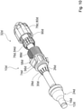
- FIG. 9 shows an alternative sealing device 10c in a perspective exploded view with an elongate object 12c.
- the sealing device 10c can be arranged in a receptacle 44c of a sealing panel 34c.
- a stabilizing element 26c and a soft element 24c are integrally connected to one another.
- the stabilizing element 26c and the soft element 24c are shown separately from one another only for the purpose of a clearer representation.
- a strain relief section 36c is designed in several parts.
- the strain relief section 36c is formed in three parts.
- the strain relief section 36c has a connection section 74c for establishing a connection between a connection element 32c and the sealing panel 34c.
- the strain relief section 36c has a strain relief element 76c for direct contacting of an elongate object 12c.
- the strain relief element 76c is designed as a lamellar insert 84c in the form of a tensioning tensioner.
- the strain relief section 36c has a pressurizing element 78c.
- the pressure application element 78c is designed as a cap nut 80c.
- the strain relief element 76c and the pressure application element 78c each have a feed-through area for the feed-through of the elongate object 12c on.
- the strain relief member 76c and the compression member 78c are disposed on the elongate object 12c.
- the connecting section 74c is integrally connected to the stabilizing element 26c.
- the connection portion 74c is arranged on the sealing panel 34c on an outside of a socket bottom 40c.
- the connecting section 74c has a first and a second latching element 56c.
- the latching elements 56c are provided for producing a latching connection between the connecting section 74c and the sealing panel 34c.
- the latching element 56c has a latching lug 58c. In the installed state, the latching element 56c engages in an opening 70c complementary thereto on the sealing panel 34c.
- the connecting section 74c has an external thread 88c.
- the pressure application element 78c has an internal thread 90c complementary to the external thread 88c of the connecting section 74c.
- the strain relief element 76c is arranged between the connecting section 74c and the pressure-exerting element 78c.
- the pressure-exerting element 78c is connected to the connecting section 74c via a non-positive connection between the external thread 88c and an internal thread 90c.
- the pressurizing member 78c applies pressure to the strain relief member 76c.
- the pressure-exerting element 78c presses the strain-relief element 76c into and/or against the connecting section 74c and thereby reduces the feed-through region of the strain-relief element 76c.
- the pressure applied by the pressurizing member 78c is transmitted to the elongate object 12c.
- the mounted state there is a slip resistance between the strain relief element 76c and the elongate object 12c in the circumferential direction.
- a non-positive connection is created between the strain relief element 76c and the elongate object 12c in the circumferential direction.
- FIG. 10 an exploded perspective view of a further sealing device 10d is shown.
- the embodiment of the sealing device 10d differs from the embodiment of the sealing device 10c only in that the sealing device 10d is provided for the passage and sealing of an elongate object 12d with a larger diameter compared to a diameter of the elongate object 12c.
- the insertion step 64c, 64d and the latching step 68c, 68d are carried out (cf. figure 5 ).
- the intermediate step 66a is omitted in the method.
- FIG. 11 shows a further alternative sealing system 38e with a further alternative sealing device 10e.
- the same reference numbers are therefore used for the same assemblies and reference is made to the explanations of Figures 1 to 8 as well as the 9 and 10 referred.
- the letters ad in the reference numerals of the embodiments in the Figures 1 to 10 by the letter e in the reference numerals of the embodiment of FIG figures 11 and 12 replaced.
- the sealing device 10e is arranged in one of receptacles 44e of a sealing panel 34e. On a mounting direction 96e of the sealing device 10e opposite A support unit 94e of a sealing system 38e is arranged on the side of the sealing panel 34e on the receptacle 44e.
- the support unit 94e is provided for receiving and fastening at least one central element of an elongate object 12e and/or of a further elongate object 112e.
- a sealing unit 14e has a sealing section 16e.
- the sealing unit 14e has a further sealing section 116e.
- the further sealing section 116e and the sealing section 16e are of identical design.
- the further sealing section 116e makes contact with a further elongate object 112e that is different from the elongate object 12e.
- the further sealing section 116e seals the further elongate object 112e by means of an intrinsic prestress.
- the further elongate object 112e and the elongate object 12e are of identical design.
- the sealing unit 14e has two cable insertion sections 22e, 122e (cf. 13 ).
- the cable insertion sections 22e, 122e each have a stabilizing element 26e, 126e (cf. 13 ).
- the cable inserting portion 22e is provided for inserting the elongated object 12e.
- the cable inserting portion 122e is provided for inserting the further elongated object 112e.
- the stabilizing elements 26e, 126e are of identical design.
- the stabilization elements 26e, 126e each have a first stabilization section 28e, 128e and a second stabilization section 30e, 130e.
- a connecting element 32e is integrally connected to the stabilizing elements 26e, 126e.
- Soft elements 24e, 124e of the stabilizing elements 26e, 126e are designed in one piece.
- the soft elements 24e, 124e and the stabilizing elements 26e, 126e are connected to one another in one piece.
- the soft elements 24e, 124e and the stabilizing elements 26e, 126e are inseparably connected to one another.
- a strain relief section 36e is designed in several parts.
- the strain relief section 36e is formed in three parts.
- the strain relief section 36e has a connection section 74e for establishing a connection between the connection element 32e and the sealing panel 34e.
- the connecting section 74e has lamellae arranged in the circumferential direction in the form of a lamellar cage 82e.
- the strain relief section 36e has a strain relief element 76e for direct contacting of an elongate object 12e.
- the strain relief element 76e is designed as a flexible element 92 .
- the flexible member 92 may be formed from rubber, neoprene, and/or a thermoplastic material.
- the strain relief element 76e has two feed-through areas for feeding through the elongate object 12e and the further elongate object 112e.
- the strain relief portion 36e includes a pressurizing member 78e.
- the pressure application element 78e is designed as a cap nut 80e.
- the strain relief element 76e and the pressure application element 78e are arranged on the elongate object 12e and on the further elongate object 112e.
- the connecting section 74e is connected in one piece to the stabilizing elements 26e, 126e.
- the connection portion 74e is arranged on the sealing panel 34e on an outside of the socket bottom 40e.
- the connecting section 74e has a first and a second latching element 56e.
- the latching elements 56e are provided for producing a latching connection between the connecting section 74e and the sealing panel 34e.
- the latching element 56e has a latching nose 58e. In the installed state, the latching element 56e engages in an opening 70e complementary thereto on the sealing panel 34e.
- the connecting section 74e has an external thread 88e.
- the pressurizing member 78e has a male thread 88e of the connecting portion 74e complementary internal thread 90e.
- the strain relief element 76e is arranged between the connecting section 74e and the pressure application element 78e.
- the pressure-exerting element 78e is connected to the connecting section 74e via a non-positive connection between the external thread 88e and the internal thread 90e.
- the strain relief element 76e is at least partially arranged inside the lamellar cage 82e.
- the pressurizing element 78e exerts pressure on the laminations of the lamina cage 82 .
- the slats exert pressure on the strain relief element 76e.
- the pressurizing member 78e presses the strain relief member 76e into the connecting portion 74e.
- the pressure application element 78e narrows the lead-through areas of the strain relief element 76e.
- the pressure applied by the pressure-exerting element 78e to the lamellar cage 82e and thus to the strain relief element 76e is transmitted to the elongate object 12e and to the further elongate object 112e.
- a non-positive connection is created between the strain relief element 76e and the elongated object 112e and the further elongated object 112e in the circumferential direction.
- figure 5 shows a flow chart of a method for sealing the object 12a in relation to the sealing panel 34a with the sealing device 10a with the sealing unit 14a.
- an insertion step 64a the sealing unit 14a is pushed onto the object 12a.
- the connecting element 32a is pushed onto the sealing unit 14a and arranged on the sealing unit 14a by means of a force fit and/or form fit.
- a latching step 68a the sealing unit 14a is connected to the sealing panel 34a by means of a latching connection by means of the connecting element 32a.
- the insertion step 64e and the latching step 68e are carried out (cf. figure 5 ).
- An intermediate step 66a is omitted in the method.
Landscapes
- Engineering & Computer Science (AREA)
- Architecture (AREA)
- Civil Engineering (AREA)
- Structural Engineering (AREA)
- Gasket Seals (AREA)
- Installation Of Indoor Wiring (AREA)
Applications Claiming Priority (3)
| Application Number | Priority Date | Filing Date | Title |
|---|---|---|---|
| DE102018113247.6A DE102018113247A1 (de) | 2018-06-04 | 2018-06-04 | Dichtvorrichtung |
| PCT/EP2018/086221 WO2019233621A1 (fr) | 2018-06-04 | 2018-12-20 | Dispositif d'étanchéité |
| EP18826355.2A EP3804060A1 (fr) | 2018-06-04 | 2018-12-20 | Dispositif d'étanchéité |
Related Parent Applications (1)
| Application Number | Title | Priority Date | Filing Date |
|---|---|---|---|
| EP18826355.2A Division EP3804060A1 (fr) | 2018-06-04 | 2018-12-20 | Dispositif d'étanchéité |
Publications (1)
| Publication Number | Publication Date |
|---|---|
| EP3940904A1 true EP3940904A1 (fr) | 2022-01-19 |
Family
ID=64899354
Family Applications (2)
| Application Number | Title | Priority Date | Filing Date |
|---|---|---|---|
| EP18826355.2A Withdrawn EP3804060A1 (fr) | 2018-06-04 | 2018-12-20 | Dispositif d'étanchéité |
| EP21191260.5A Withdrawn EP3940904A1 (fr) | 2018-06-04 | 2018-12-20 | Dispositif d'étanchéité |
Family Applications Before (1)
| Application Number | Title | Priority Date | Filing Date |
|---|---|---|---|
| EP18826355.2A Withdrawn EP3804060A1 (fr) | 2018-06-04 | 2018-12-20 | Dispositif d'étanchéité |
Country Status (4)
| Country | Link |
|---|---|
| US (1) | US20210234353A1 (fr) |
| EP (2) | EP3804060A1 (fr) |
| DE (1) | DE102018113247A1 (fr) |
| WO (1) | WO2019233621A1 (fr) |
Citations (9)
| Publication number | Priority date | Publication date | Assignee | Title |
|---|---|---|---|---|
| US5442140A (en) | 1993-10-05 | 1995-08-15 | Homac Mfg. Company | Conduit and cable sealer |
| WO1997002635A1 (fr) * | 1995-06-30 | 1997-01-23 | N.V. Raychem S.A. | Appareil servant a entourer une partie d'un objet allonge |
| US6329601B1 (en) * | 1996-06-17 | 2001-12-11 | David L. Bulford | Service wire splice housing |
| EP1643604A1 (fr) | 2004-10-02 | 2006-04-05 | Hauff-Technik GmbH & Co. KG | Dispositif d'étanchéité à l'égard de gaz ou de fluides entre deux pièces adjacentes |
| DE102012006786A1 (de) * | 2012-04-03 | 2013-10-10 | Icotek Project Gmbh & Co. Kg | Vorrichtung zum Durchführen eines Stranges durch ein Blech |
| US8648258B2 (en) * | 2008-10-21 | 2014-02-11 | 3M Innovative Properties Company | Mechanical cable entry port |
| EP2764591A2 (fr) * | 2011-10-07 | 2014-08-13 | Phoenix Contact GmbH & Co. KG | Traversée de câbles et procédé de montage d'une traversée de câbles |
| DE202015102280U1 (de) * | 2015-05-05 | 2016-05-10 | Conta-Clip Verbindungstechnik Gmbh | Anordnung mit einer Wanddurchführung für mehrere Kabel und Bausatz |
| DE202016104057U1 (de) | 2016-07-25 | 2017-10-27 | Woco Industrietechnik Gmbh | Tülle |
Family Cites Families (10)
| Publication number | Priority date | Publication date | Assignee | Title |
|---|---|---|---|---|
| DE10313989B4 (de) * | 2003-03-27 | 2012-07-12 | Murrplastik Systemtechnik Gmbh | Kabeldurchführungsvorrichtung |
| US7186929B2 (en) * | 2005-07-08 | 2007-03-06 | 3M Innovative Properties Company | Sealing member for an entry port |
| DE202006017659U1 (de) * | 2006-03-18 | 2007-08-02 | Weidmüller Interface GmbH & Co. KG | Dichtung für eine Gehäusedurchführung für ein Kabel |
| US7736165B2 (en) * | 2007-07-16 | 2010-06-15 | Tyco Electronics Corporation | Electrical connector assemblies and methods for forming and using the same |
| US8490513B2 (en) * | 2010-03-19 | 2013-07-23 | Avc Industrial Corp. | Cable gland and gasket ring assembly |
| DE102010037463A1 (de) * | 2010-09-10 | 2012-03-15 | Phoenix Contact Gmbh & Co. Kg | Rahmen eines Kabeleinführungssystems und Kabeltülle hierfür |
| US8686289B2 (en) * | 2011-07-14 | 2014-04-01 | Channell Commercial Corporation | Sealing mechanism and method for drop cable splice enclosures |
| TWM419290U (en) * | 2011-07-28 | 2011-12-21 | Hon Hai Prec Ind Co Ltd | Waterproof structure for connector |
| DE102013205666A1 (de) * | 2013-03-28 | 2014-10-02 | Lapp Engineering & Co. | Kabeldurchführung |
| EP3150890A1 (fr) * | 2015-09-29 | 2017-04-05 | HILTI Aktiengesellschaft | Passage de conduite destine a passer des conduites a travers un composant |
-
2018
- 2018-06-04 DE DE102018113247.6A patent/DE102018113247A1/de not_active Withdrawn
- 2018-12-20 WO PCT/EP2018/086221 patent/WO2019233621A1/fr not_active Ceased
- 2018-12-20 EP EP18826355.2A patent/EP3804060A1/fr not_active Withdrawn
- 2018-12-20 EP EP21191260.5A patent/EP3940904A1/fr not_active Withdrawn
- 2018-12-20 US US15/734,598 patent/US20210234353A1/en not_active Abandoned
Patent Citations (10)
| Publication number | Priority date | Publication date | Assignee | Title |
|---|---|---|---|---|
| US5442140A (en) | 1993-10-05 | 1995-08-15 | Homac Mfg. Company | Conduit and cable sealer |
| WO1997002635A1 (fr) * | 1995-06-30 | 1997-01-23 | N.V. Raychem S.A. | Appareil servant a entourer une partie d'un objet allonge |
| US6329601B1 (en) * | 1996-06-17 | 2001-12-11 | David L. Bulford | Service wire splice housing |
| EP1643604A1 (fr) | 2004-10-02 | 2006-04-05 | Hauff-Technik GmbH & Co. KG | Dispositif d'étanchéité à l'égard de gaz ou de fluides entre deux pièces adjacentes |
| US8648258B2 (en) * | 2008-10-21 | 2014-02-11 | 3M Innovative Properties Company | Mechanical cable entry port |
| EP2764591A2 (fr) * | 2011-10-07 | 2014-08-13 | Phoenix Contact GmbH & Co. KG | Traversée de câbles et procédé de montage d'une traversée de câbles |
| EP2764591B1 (fr) | 2011-10-07 | 2015-09-16 | Phoenix Contact GmbH & Co. KG | Traversée de câbles et procédé de montage d'une traversée de câbles |
| DE102012006786A1 (de) * | 2012-04-03 | 2013-10-10 | Icotek Project Gmbh & Co. Kg | Vorrichtung zum Durchführen eines Stranges durch ein Blech |
| DE202015102280U1 (de) * | 2015-05-05 | 2016-05-10 | Conta-Clip Verbindungstechnik Gmbh | Anordnung mit einer Wanddurchführung für mehrere Kabel und Bausatz |
| DE202016104057U1 (de) | 2016-07-25 | 2017-10-27 | Woco Industrietechnik Gmbh | Tülle |
Also Published As
| Publication number | Publication date |
|---|---|
| EP3804060A1 (fr) | 2021-04-14 |
| DE102018113247A1 (de) | 2019-12-05 |
| US20210234353A1 (en) | 2021-07-29 |
| WO2019233621A1 (fr) | 2019-12-12 |
Similar Documents
| Publication | Publication Date | Title |
|---|---|---|
| EP2764591B1 (fr) | Traversée de câbles et procédé de montage d'une traversée de câbles | |
| EP1922793B1 (fr) | Jeu de pieces detachees ou kit comportant au moins deux types a dimensions differentes de dispositifs de fixation de cables par vissage | |
| EP3292604B1 (fr) | Procédé de réalisation d'une traversée mural pour plusieurs câbles et ensemble | |
| DE2556878C3 (de) | Lösbare Klemm-Muffe für ein Kabel oder einen Schlauch | |
| EP4127543B1 (fr) | Raccord de type enfichable ayant un verrouillage de préassemblage | |
| EP2712413B1 (fr) | Dispositif de raccordement permettant de raccorder une conduite de fluides | |
| AT516151B1 (de) | Steckverbinderbaugruppe zum Verbinden von Leitungen | |
| EP3893343A1 (fr) | Dispositif de passage et de décharge de traction des cordes | |
| EP2614565B1 (fr) | Traversée de câbles | |
| DE3033921A1 (de) | Selbstverriegelnde klemmschelle | |
| DE102020208235A1 (de) | Vorrichtung zur Durchführung von Strängen | |
| EP0854298A1 (fr) | anneau de fixation | |
| EP3557084A1 (fr) | Élément de raccordement permettant de raccorder des éléments profilés | |
| EP2848848A1 (fr) | Element d'étanchéité | |
| EP2208676B1 (fr) | Serre-joint | |
| DE10012157C1 (de) | Tülle | |
| EP4314448A1 (fr) | Poignée d'actionnement | |
| EP1503471A2 (fr) | Plaque de traversée de câble | |
| DE20120029U1 (de) | Stutzen für eine Behälterwand | |
| WO2017140721A1 (fr) | Dispositif de boîte de jonction, système modulaire pour réaliser une boîte de jonction et procédé de réalisation d'une boîte de jonction à partir d'un système modulaire | |
| DE102005022937B4 (de) | Verfahren zur Herstellung einer längswasserdichten Anordnung eines Leitungsstranges in einer elastischen Tülle | |
| EP1740903A2 (fr) | Dispositif de mesure de deplacement | |
| EP3303062B1 (fr) | Arrangement pour la fixation d'un element en forme de reglette | |
| DE102015011518B4 (de) | Abdeckungseinrichtung für einen Unterboden eines Kraftfahrzeugs sowie entsprechendes Kraftfahrzeug | |
| WO2019233621A1 (fr) | Dispositif d'étanchéité |
Legal Events
| Date | Code | Title | Description |
|---|---|---|---|
| PUAI | Public reference made under article 153(3) epc to a published international application that has entered the european phase |
Free format text: ORIGINAL CODE: 0009012 |
|
| STAA | Information on the status of an ep patent application or granted ep patent |
Free format text: STATUS: THE APPLICATION HAS BEEN PUBLISHED |
|
| AC | Divisional application: reference to earlier application |
Ref document number: 3804060 Country of ref document: EP Kind code of ref document: P |
|
| AK | Designated contracting states |
Kind code of ref document: A1 Designated state(s): AL AT BE BG CH CY CZ DE DK EE ES FI FR GB GR HR HU IE IS IT LI LT LU LV MC MK MT NL NO PL PT RO RS SE SI SK SM TR |
|
| STAA | Information on the status of an ep patent application or granted ep patent |
Free format text: STATUS: THE APPLICATION IS DEEMED TO BE WITHDRAWN |
|
| 18D | Application deemed to be withdrawn |
Effective date: 20220720 |