EP3941125A1 - Datenübertragungsverfahren und -vorrichtung, benutzergerät, basisstation, kommunikationssystem und speichermedium - Google Patents
Datenübertragungsverfahren und -vorrichtung, benutzergerät, basisstation, kommunikationssystem und speichermedium Download PDFInfo
- Publication number
- EP3941125A1 EP3941125A1 EP20769058.7A EP20769058A EP3941125A1 EP 3941125 A1 EP3941125 A1 EP 3941125A1 EP 20769058 A EP20769058 A EP 20769058A EP 3941125 A1 EP3941125 A1 EP 3941125A1
- Authority
- EP
- European Patent Office
- Prior art keywords
- resource
- pusch
- preamble sequence
- pusch resource
- configuration information
- Prior art date
- Legal status (The legal status is an assumption and is not a legal conclusion. Google has not performed a legal analysis and makes no representation as to the accuracy of the status listed.)
- Pending
Links
Images



Classifications
-
- H—ELECTRICITY
- H04—ELECTRIC COMMUNICATION TECHNIQUE
- H04W—WIRELESS COMMUNICATION NETWORKS
- H04W72/00—Local resource management
- H04W72/12—Wireless traffic scheduling
- H04W72/1263—Mapping of traffic onto schedule, e.g. scheduled allocation or multiplexing of flows
- H04W72/1268—Mapping of traffic onto schedule, e.g. scheduled allocation or multiplexing of flows of uplink data flows
-
- H—ELECTRICITY
- H04—ELECTRIC COMMUNICATION TECHNIQUE
- H04W—WIRELESS COMMUNICATION NETWORKS
- H04W72/00—Local resource management
- H04W72/02—Selection of wireless resources by user or terminal
-
- H—ELECTRICITY
- H04—ELECTRIC COMMUNICATION TECHNIQUE
- H04L—TRANSMISSION OF DIGITAL INFORMATION, e.g. TELEGRAPHIC COMMUNICATION
- H04L27/00—Modulated-carrier systems
- H04L27/18—Phase-modulated carrier systems, i.e. using phase-shift keying
-
- H—ELECTRICITY
- H04—ELECTRIC COMMUNICATION TECHNIQUE
- H04L—TRANSMISSION OF DIGITAL INFORMATION, e.g. TELEGRAPHIC COMMUNICATION
- H04L27/00—Modulated-carrier systems
- H04L27/26—Systems using multi-frequency codes
- H04L27/2601—Multicarrier modulation systems
- H04L27/2602—Signal structure
- H04L27/26025—Numerology, i.e. varying one or more of symbol duration, subcarrier spacing, Fourier transform size, sampling rate or down-clocking
-
- H—ELECTRICITY
- H04—ELECTRIC COMMUNICATION TECHNIQUE
- H04L—TRANSMISSION OF DIGITAL INFORMATION, e.g. TELEGRAPHIC COMMUNICATION
- H04L27/00—Modulated-carrier systems
- H04L27/26—Systems using multi-frequency codes
- H04L27/2601—Multicarrier modulation systems
- H04L27/2626—Arrangements specific to the transmitter only
- H04L27/2627—Modulators
- H04L27/2634—Inverse fast Fourier transform [IFFT] or inverse discrete Fourier transform [IDFT] modulators in combination with other circuits for modulation
- H04L27/2636—Inverse fast Fourier transform [IFFT] or inverse discrete Fourier transform [IDFT] modulators in combination with other circuits for modulation with FFT or DFT modulators, e.g. standard single-carrier frequency-division multiple access [SC-FDMA] transmitter or DFT spread orthogonal frequency division multiplexing [DFT-SOFDM]
-
- H—ELECTRICITY
- H04—ELECTRIC COMMUNICATION TECHNIQUE
- H04L—TRANSMISSION OF DIGITAL INFORMATION, e.g. TELEGRAPHIC COMMUNICATION
- H04L5/00—Arrangements affording multiple use of the transmission path
- H04L5/003—Arrangements for allocating sub-channels of the transmission path
- H04L5/0053—Allocation of signalling, i.e. of overhead other than pilot signals
-
- H—ELECTRICITY
- H04—ELECTRIC COMMUNICATION TECHNIQUE
- H04L—TRANSMISSION OF DIGITAL INFORMATION, e.g. TELEGRAPHIC COMMUNICATION
- H04L5/00—Arrangements affording multiple use of the transmission path
- H04L5/0091—Signalling for the administration of the divided path, e.g. signalling of configuration information
- H04L5/0094—Indication of how sub-channels of the path are allocated
-
- H—ELECTRICITY
- H04—ELECTRIC COMMUNICATION TECHNIQUE
- H04W—WIRELESS COMMUNICATION NETWORKS
- H04W72/00—Local resource management
- H04W72/04—Wireless resource allocation
- H04W72/044—Wireless resource allocation based on the type of the allocated resource
- H04W72/0446—Resources in time domain, e.g. slots or frames
-
- H—ELECTRICITY
- H04—ELECTRIC COMMUNICATION TECHNIQUE
- H04W—WIRELESS COMMUNICATION NETWORKS
- H04W72/00—Local resource management
- H04W72/20—Control channels or signalling for resource management
- H04W72/23—Control channels or signalling for resource management in the downlink direction of a wireless link, i.e. towards a terminal
-
- H—ELECTRICITY
- H04—ELECTRIC COMMUNICATION TECHNIQUE
- H04W—WIRELESS COMMUNICATION NETWORKS
- H04W74/00—Wireless channel access
- H04W74/002—Transmission of channel access control information
- H04W74/004—Transmission of channel access control information in the uplink, i.e. towards network
-
- H—ELECTRICITY
- H04—ELECTRIC COMMUNICATION TECHNIQUE
- H04W—WIRELESS COMMUNICATION NETWORKS
- H04W74/00—Wireless channel access
- H04W74/002—Transmission of channel access control information
- H04W74/006—Transmission of channel access control information in the downlink, i.e. towards the terminal
-
- H—ELECTRICITY
- H04—ELECTRIC COMMUNICATION TECHNIQUE
- H04W—WIRELESS COMMUNICATION NETWORKS
- H04W74/00—Wireless channel access
- H04W74/08—Non-scheduled access, e.g. ALOHA
- H04W74/0833—Random access procedures, e.g. with 4-step access
-
- H—ELECTRICITY
- H04—ELECTRIC COMMUNICATION TECHNIQUE
- H04W—WIRELESS COMMUNICATION NETWORKS
- H04W74/00—Wireless channel access
- H04W74/08—Non-scheduled access, e.g. ALOHA
- H04W74/0833—Random access procedures, e.g. with 4-step access
- H04W74/0836—Random access procedures, e.g. with 4-step access with 2-step access
-
- H—ELECTRICITY
- H04—ELECTRIC COMMUNICATION TECHNIQUE
- H04W—WIRELESS COMMUNICATION NETWORKS
- H04W74/00—Wireless channel access
- H04W74/08—Non-scheduled access, e.g. ALOHA
- H04W74/0866—Non-scheduled access, e.g. ALOHA using a dedicated channel for access
Definitions
- the present application relates to the field of communications, for example, a data transmission method and apparatus, a user equipment, a base station, a communication system and a storage medium.
- a random access message A (msgA) or a data packet message is transmitted in a physical random access channel (PRACH) resource and/or a physical uplink shared channel (PUSCH) resource.
- PRACH physical random access channel
- PUSCH physical uplink shared channel
- a user equipment (UE) maps a preamble sequence onto the PRACH resource according to certain preamble sequence configuration information.
- the PUSCH resource carries at least a UE identification (ID).
- ID UE identification
- the value of the size of this ID information may be 56 bits, 72 bits, 144 bits 208 bits or the like.
- the payload size of the preceding message may be greater than 208 bits.
- Different payload sizes may correspond to resource configurations of different PUSCH resources.
- the UE cannot select preamble sequence configuration information corresponding to the resource configuration of the PUSCH resource of the UE and thus cannot map a preamble sequence according to the preamble sequence configuration information.
- Embodiments of the present application provide a data transmission method.
- the method includes: abiding by a mapping relationship between the resource configuration of a PUSCH resource and preamble sequence configuration information according to the resource configuration of the PUSCH resource and determining preamble sequence configuration information corresponding to the resource configuration of the PUSCH resource; mapping a preamble sequence onto a PRACH resource according to the preamble sequence configuration information; and sending a message containing the PRACH resource and the PUSCH resource.
- Embodiments of the present application provide a data transmission method.
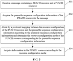
- the method includes receiving a message containing a PRACH resource and a PUSCH resource; acquiring the preamble sequence configuration information of the PRACH resource in the message; abiding by a prestored mapping relationship between the resource configuration of the PUSCH resource and the preamble sequence configuration information according to the preamble sequence configuration information and determining the resource configuration mode of the PUSCH resource corresponding to the preamble sequence configuration information; and acquiring information in the PUSCH resource according to the resource configuration mode.
- Embodiments of the present application provide a data transmission apparatus.
- the apparatus includes a first search module configured to abide by a mapping relationship between the resource configuration of a PUSCH resource and preamble sequence configuration information according to the resource configuration of the PUSCH resource and determine preamble sequence configuration information corresponding to the resource configuration of the PUSCH resource; a mapping module configured to map a preamble sequence onto a PRACH resource according to the preamble sequence configuration information; and a first sending module configured to send a message containing the PRACH resource and the PUSCH resource.
- Embodiments of the present application provide a data transmission apparatus.
- the apparatus includes a second receiving module configured to receive a message containing a PRACH resource and a PUSCH resource; a first acquisition module configured to acquire the preamble sequence configuration information of the PRACH resource in the message; a second search module configured to abide by a prestored mapping relationship between the resource configuration of the PUSCH resource and the preamble sequence configuration information according to the preamble sequence configuration information and determine the resource configuration mode of the PUSCH resource corresponding to the preamble sequence configuration information; and a second acquisition module configured to acquire information in the PUSCH resource according to the resource configuration mode.
- Embodiments of the present application provide a UE for data transmission.
- the UE includes one or more processors and a memory.
- the memory is configured to store one or more programs.
- the one or more programs When executed by the one or more processors, the one or more programs cause the one or more processors to perform any implementation of the preceding first data transmission method.
- Embodiments of the present application provide a base station for data transmission.
- the base station includes one or more processors and a memory.
- the memory is configured to store one or more programs.
- the one or more programs When executed by the one or more processors, the one or more programs cause the one or more processors to perform any implementation of the preceding second data transmission method.
- Embodiments of the present application provide a communication system.
- the system includes the UE and the base station of embodiments of the present application.
- Embodiments of the present application provide a storage medium.
- the storage medium stores a computer program. When executed by a processor the computer program causes the processor to perform any method of embodiments of the present application.
- the corresponding preamble sequence configuration information may be selected according to the resource configuration of the PUSCH resource, and the preamble sequence is mapped onto the PRACH resource by using the preamble sequence configuration information. In this manner, it facilitates the UE to select the transmission resource according to the resource configuration of the PUSCH resource. Further, it is easier for the base station to receive the message.
- the 5th-generation New Radio in unlicensed spectrum introduces a new resource mapping mode to PRACH. That is, a preamble sequence is mapped onto PRACH in an interlace manner.
- Table 1 describes possible combinations of a number (denoted by M in Table 1) of different interlace blocks and a number (denoted by N in Table 1) of resource blocks (RBs) of each interlace block in the case of a transmit bandwidth of 20 MHz and different subcarrier spacings (SCSs).
- PRACH interlace mapping modes include, but are not limited to, uniform physical resource block level (Uniform PRB-level) interlace mapping, non-uniform PRB-level interlace mapping, uniform resource element (RE) level interlace mapping, and contiguous mapping.
- Uniform PRB-level uniform physical resource block level
- RE uniform resource element
- FIG. 1 is a flowchart of implementing the data transmission method according to embodiments of the present application. The method includes the steps described hereinafter.
- step S11 a mapping relationship between the resource configuration of a PUSCH resource and preamble sequence configuration information is abided by according to the resource configuration of the PUSCH resource, and preamble sequence configuration information corresponding to the resource configuration is determined.
- step S12 a preamble sequence is mapped onto a PRACH resource according to the preamble sequence configuration information.
- step S13 a message containing the PRACH resource and the PUSCH resource is sent.
- information in the PUSCH resource includes at least one of: a UE ID or user plane data.
- the preceding message may be a random access message or a data packet message.
- the method of this embodiment of the present application can be applied to a UE.
- the method may further include that the UE receives the mapping relationship between the resource configuration of the PUSCH resource and the preamble sequence configuration information, where the mapping relationship is sent by a base station.
- the preamble sequence configuration information may include at least one of: a preamble ID, an interlace ID, the number (that is, N in Table 1) of RBs contained in each interlace block occupied by the preamble sequence, or time-frequency position information of the preamble sequence.
- the preamble ID may include at least one of: a preamble index, a preamble group index, or a sequence number of a preamble in a preamble group.
- the interlace ID may include at least one of an interlace index, an interlace group index, or a sequence number of an interlace block in an interlace block group.
- the UE After determining the resource configuration of the PUSCH resource, through step S 11, the UE can determine, according to the mapping relationship between the resource configuration of the PUSCH resource and the preamble sequence configuration information, the preamble sequence configuration information used for mapping the preamble sequence.
- the resource configuration of the PUSCH resource includes at least one of: a demodulation reference signal (DMRS) port index corresponding to the PUSCH resource, frequency domain resource information of the PUSCH resource, time domain resource information of the PUSCH resource, a payload size of the message, a waveform, an SCS, or a modulation and coding scheme.
- DMRS demodulation reference signal
- the frequency domain resource information of the PUSCH resource may include a number of RBs occupied by the frequency domain resource of the PUSCH resource and an offset of the position of the frequency domain resource of the PUSCH resource relative to the frequency domain position of the preamble sequence.
- the position of the frequency domain resource of the PUSCH resource may include at least one of: a RB index of the start point of the frequency domain resource of the PUSCH resource, an interlace index of the frequency domain resource of the PUSCH resource, or a RB index of the frequency domain resource of the PUSCH resource in an interlace block.
- the time domain resource information of the PUSCH resource may include a number of slots or mini-slots occupied by the time domain resource of the PUSCH resource and an offset of the position of the time domain resource of the PUSCH resource relative to the time domain position of the preamble sequence.
- the position of the time domain resource of the PUSCH resource includes at least one of: a system frame number (SFN) of the start point of the time domain resource of the PUSCH resource, a subframe number of the start point of the time domain resource of the PUSCH resource, a slot position or mini-slot position of the start point of the time domain resource of the PUSCH resource, or a start symbol of the time domain resource of the PUSCH resource.
- SFN system frame number
- the UE when determining the resource configuration of the PUSCH resource of the UE, the UE may first determine a modulation and coding scheme (MCS) level according to the payload size and channel condition of the UE. For example, a UE located in the center of a cell and having a better channel condition may transmit data by using MCS levels of a higher MCS order, and a UE having a worse channel condition may transmit data by using MCS levels of a lower MCS order. Then, the UE determines the resource configuration of the PUSCH resource of the UE according to the determined MCS level, for example, the size of an occupied time-frequency resource (including the number of RBs).
- MCS modulation and coding scheme
- the preamble resource pools may be preamble resource pools of NR/Long-Term Evolution (LTE) or may be newly added preamble resource pools.
- LTE Long-Term Evolution
- the value of a typical granularity is 1 RB, 2 RBs, 3 RBs or 6 RBs.
- the UE may select a preamble resource pool according to a reference signal received power (RSRP) and a transport block size (TBSize).
- RSRP reference signal received power
- TBSize transport block size
- the UE may select a preamble resource pool corresponding to the maximum RB resource granularity.
- the UE may select a preamble resource pool corresponding to a relatively large RB resource granularity.
- the UE may select a preamble resource pool corresponding to the minimum RB resource granularity.
- the MCS level can be determined.
- the RSRP may be replaced by a pathloss.
- the preceding preamble resource pools may have an equal size.
- the size of each preamble resource pool may be determined according to the possible distribution of the sizes of different pieces of information carried in different PUSCH resources.
- user's DMRS-port-related information such as a DMRS port index or a DMRS orthogonal cover code (OCC) pattern is related to the interlace ID and the preamble ID.
- user's DMRS-port-related information such as a DMRS port index or a DMRS OCC pattern is related to the preamble ID.
- the UE may calculate the MCS level according to the payload size of the UE and the size of a selected time-frequency resource block. For example, if a larger time-frequency resource block is selected, the MCS order used may be lower.
- the MCS used in modulation of at least part of the payload size includes at least one of binary phase shift keying (BPSK) modulation, pi/2-BPSK modulation and quadrature phase shift keying (QPSK) modulation.
- BPSK binary phase shift keying
- QPSK quadrature phase shift keying
- the UE may determine, according to a preset rule, the preamble sequence configuration information corresponding to the resource configuration of the PUSCH resource.
- the preset rule may be the mapping relationship between the resource configuration of the PUSCH resource and the preamble sequence configuration information.
- the preset rule is sent by the base station to the UE in advance.
- the preset rule may be based on the interlace index, the number of RBs occupied by the interlace block, a possible start or end point of the interlace block, or preamble-sequence-related information in the interlace block.
- the related information may include the preamble index, cyclic shift (CS) information of the preamble sequence, the size of the bandwidth occupied by the preamble in the interlace block, the number of REs of the preamble in the interlace block, and the time-frequency position of the preamble.
- CS cyclic shift
- the MCS mode, the payload size and the traffic model used by the UE may be indicated by information related to the interlace block in which the user's preamble is located.
- the start point of the interlace block, the end point of the interlace block, the size range of the interlace block, the interlace index, the preamble index, the CS of the preamble, or the number of RBs contained in the interlace block corresponds to a different resource configuration of the PUSCH resource.
- the interlace ID indicates a different DMRS port index and a system-supported resource granularity item for a different PUSCH scheduling.
- Tables 2A and 2B describe examples of the mapping relationship between the resource configuration of the PUSCH resource and the preamble sequence configuration information in different interlace patterns in embodiment of the present application.
- the first column describes the preamble sequence configuration information, specifically, interlace index; and the last six columns describe the resource configuration of the PUSCH resource, including the DMRS port index, the frequency domain resource information of the PUSCH resource and the time domain resource information of the PUSCH resource.
- the UE After determining the resource configuration of the PUSCH resource of the UE, the UE abides by the mapping relationship in Table 2A according to the resource configuration of the PUSCH resource and determines the corresponding preamble sequence configuration information; and then performs mapping of the preamble sequence according to the preamble sequence configuration information.
- the first column describes the preamble sequence configuration information, specifically, interlace index, and the last seven columns describe the resource configuration of the PUSCH resource, including the DMRS port index, the frequency domain resource information of the PUSCH resource and the time domain resource information of the PUSCH resource.
- the UE After determining the resource configuration of the PUSCH resource of the UE, the UE abides by the mapping relationship in Table 2B according to the resource configuration of the PUSCH resource and determines the corresponding preamble sequence configuration information; and then performs mapping of the preamble sequence according to the preamble sequence configuration information.
- the mappings relationship described in Tables 2A and 2B may be applied to a scenario in which the preamble resource is 15 kHz and an NR type I front loaded symbol serves as an OFDM symbol.
- the association rules described in Tables 2A and 2B are determined according to information such as the DMRS port configuration of PUSCH and the size of possibly occupied RBs, that is, multiplexed on one resource and shifted apart in the time domain and the frequency domain.
- the value range of the DMRS port index is integers from 1 to 4, that is, includes 1, 2, 3 and 4.
- the value range of the DMRS port index may include other ranges, for example, integers from 0 to 3, that is, 0, 1, 2 and 3; or integers from 0 to 5, that is, 0, 1, 2, 3, 4 and 5; or integers from 0 to 7, that is, 0, 1, 2, 3, 4, 5, 6 and 7; or integers from 0 to 11, that is, 0, 1, 2, 3, 4, 5, 6, 7, 8, 9, 10 and 11; or integers from 1 to 4, that is, 1, 2, 3 and 4; or integers from 1 to 6, that is, 1, 2, 3, 4, 5 and 6; or integers from 1 to 8, that is, 1, 2, 3, 4, 5, 6, 7 and 8; or integers from 1 to 12, that is, 1, 2, 3, 4, 5, 6, 7, 8, 9, 10, 11 and 12.
- Table 3 describes an example of the mapping relationship between the resource configuration of the PUSCH resource and the preamble sequence configuration information in different interlace patterns in embodiments of the present application.
- the first column describes the preamble sequence configuration information: the number of RBs contained in each interlace block occupied by the preamble sequence
- the second column describes the resource configuration of the PUSCH resource: waveform.
- the possible value of the waveform may be a cyclic prefix orthogonal frequency division multiplexing (CP-OFDM) waveform or a discrete Fourier transform spread orthogonal frequency division multiplexing (DFT-S-OFDM) waveform.
- the UE After determining the resource configuration of the PUSCH resource of the UE, the UE abides by the mapping relationship in Table 3 according to the resource configuration of the PUSCH resource and determines the corresponding preamble sequence configuration information; and then performs mapping of the preamble sequence according to the preamble sequence configuration information.
- Table 3 Number of RBs Contained in Each Interlace Block Occupied by Preamble Sequence Waveform 13 CP-OFDM 12 DFT-S-OFDM
- the value of N is preferably a multiple of 2, 3 or 5 to facilitate waveform generation. Therefore, in the case where both 12 RBs and 13 RBs exist and two waveforms are indicated, the case where 13 RBs are contained in each interlace block occupied by the preamble sequence indicates the CP-OFDM waveform, and the case where 12 RBs are contained in each interlace block occupied by the preamble sequence indicates the DFT-S-OFDM waveform.
- Table 4 describes an example of the mapping relationship between the resource configuration of the PUSCH resource and the preamble sequence configuration information in different interlace patterns in embodiments of the present application.
- the first column describes the preamble sequence configuration information: the number of RBs contained in each interlace block occupied by the preamble sequence
- the second column describes the resource configuration of the PUSCH resource: payload size.
- the possible value of the payload size may be 56 bits or 72 bits.
- the UE After determining the resource configuration of the PUSCH resource of the UE, the UE abides by the mapping relationship in Table 4 according to the resource configuration of the PUSCH resource and determines the corresponding preamble sequence configuration information; and then performs mapping of the preamble sequence according to the preamble sequence configuration information.
- Table 4 Number of RBs Contained in Each Interlace Block Occupied by Preamble Sequence Payload Size 10 56 bits 11 72 bits
- Table 5A describes an example of the mapping relationship between the resource configuration of the PUSCH resource and the preamble sequence configuration information in different interlace patterns in embodiments of the present application.
- the first column describes the preamble sequence configuration information: interlace index
- the second column describes the resource configuration of the PUSCH resource: waveform.
- the possible value of the waveform may be a CP-OFDM waveform or a DFT-S-OFDM waveform.
- the UE After determining the resource configuration of the PUSCH resource of the UE, the UE abides by the mapping relationship in Table 5A according to the resource configuration of the PUSCH resource and determines the corresponding preamble sequence configuration information; and then performs mapping of the preamble sequence according to the preamble sequence configuration information.
- Table 5A Interlace Index Waveform 1 to K CP-OFDM K + 1 to M DFT-S-OFDM
- the interlace index may have more than two values; therefore, in Table 5A, some possible values of the interlace index correspond to the CP-OFDM waveform, and other possible values of the interlace index correspond to the DFT-S-OFDM waveform.
- K is an integer greater than 1 and less than (M - 1).
- Table 5 describes merely an example.
- interlace indexes corresponding to one type of waveform may be discontinuous.
- Table 5B describes an example of the mapping relationship between the resource configuration of the PUSCH resource and the preamble sequence configuration information in different interlace patterns in embodiments of the present application.
- the first column describes the preamble sequence configuration information: interlace group index
- the second column describes the resource configuration of the PUSCH resource: waveform.
- the possible value of the waveform may be a CP-OFDM waveform or a DFT-S-OFDM waveform.
- the UE After determining the resource configuration of the PUSCH resource of the UE, the UE abides by the mapping relationship in Table 5B according to the resource configuration of the PUSCH resource and determines the corresponding preamble sequence configuration information; and then performs mapping of the preamble sequence according to the preamble sequence configuration information.
- Table 5B Interlace Group Index Waveform 1 CP-OFDM 2 DFT-S-OFDM
- Table 6A describes an example of the mapping relationship between the resource configuration of the PUSCH resource and the preamble sequence configuration information in different interlace patterns in embodiments of the present application.
- the first column describes the preamble sequence configuration information: interlace index
- the second column describes the resource configuration of the PUSCH resource: payload size.
- the possible value of the payload size may be 56 bits or 72 bits.
- the UE After determining the resource configuration of the PUSCH resource of the UE, the UE abides by the mapping relationship in Table 6A according to the resource configuration of the PUSCH resource and determines the corresponding preamble sequence configuration information; and then performs mapping of the preamble sequence according to the preamble sequence configuration information.
- Table 6A interlace index payload size 1 to Q 56 bits Q + 1 to M 72 bits
- the interlace index may have more than two values; therefore, in Table 6A, some possible values of the interlace index correspond to 56 bits, and other possible values of the interlace index correspond to 72 bits.
- Q is an integer greater than 1 and less than M - 1.
- Table 6A describes merely an example.
- interlace indexes corresponding to one payload size may be discontinuous.
- the payload size may have values such as 144 bits and 208 bits.
- different values of the interlace index may correspond to values of four or more payload sizes.
- Table 6B describes an example of the mapping relationship between the resource configuration of the PUSCH resource and the preamble sequence configuration information in different interlace patterns in embodiments of the present application.
- the first column describes the preamble sequence configuration information: interlace group index
- the second column describes the resource configuration of the PUSCH resource: payload size.
- the possible value of the payload size may be 56 bits or 72 bits.
- the UE After determining the resource configuration of the PUSCH resource of the UE, the UE abides by the mapping relationship in Table 6B according to the resource configuration of the PUSCH resource and determines the corresponding preamble sequence configuration information; and then performs mapping of the preamble sequence according to the preamble sequence configuration information.
- Table 6B Interlace Group Index Payload Size 1 56 bits 2 72 bits
- Table 7A describes an example of the mapping relationship between the resource configuration of the PUSCH resource and the preamble sequence configuration information in different interlace patterns in embodiments of the present application.
- the first column describes the preamble sequence configuration information: interlace index
- the second column describes the resource configuration of the PUSCH resource: combination of waveform and payload size.
- the UE After determining the resource configuration of the PUSCH resource of the UE, the UE abides by the mapping relationship in Table 7A according to the resource configuration of the PUSCH resource and determines the corresponding preamble sequence configuration information; and then performs mapping of the preamble sequence according to the preamble sequence configuration information.
- Table 7A Interlace Index Waveform and Payload Size 1 to G CP-OFDM and 56 bits (G + 1) to L DFT-S-OFDM and 72 bits (L + 1) to T CP-OFDM and 72 bits (T + 1) to M DFT-S-OFDM and 56 bits
- the combination of waveform and payload size may have four possible values.
- G, L and T are integers greater than 1 and less than M - 1, and G ⁇ L ⁇ T.
- the three integers G, L and T divide some possible values of the interlace index into four parts. Each part corresponds to one possible value of the combination of waveform and payload size.
- Table 7A describes merely an example.
- interlace indexes corresponding to one combination of waveform and payload size may be discontinuous.
- Table 7B describes an example of the mapping relationship between the resource configuration of the PUSCH resource and the preamble sequence configuration information in different interlace patterns in embodiments of the present application.
- the first column describes the preamble sequence configuration information: interlace group index
- the second column describes the resource configuration of the PUSCH resource: combination of waveform and payload size.
- the UE After determining the resource configuration of the PUSCH resource of the UE, the UE abides by the mapping relationship in Table 7B according to the resource configuration of the PUSCH resource and determines the corresponding preamble sequence configuration information; and then performs mapping of the preamble sequence according to the preamble sequence configuration information.
- Table 7B Interlace Group Index Waveform and Payload Size 1 CP-OFDM and 56 bits 2 DFT-S-OFDM and 72 bits 3 CP-OFDM and 72 bits 4 DFT-S-OFDM and 56 bits
- Table 8A describes an example of the mapping relationship between the resource configuration of the PUSCH resource and the preamble sequence configuration information in different interlace patterns in embodiments of the present application.
- the first column describes the preamble sequence configuration information: interlace index
- the second column describes the resource configuration of the PUSCH resource: SCS.
- the possible value of the SCS may be 15 kHz, 30 kHz or 60 kHz.
- the UE After determining the resource configuration of the PUSCH resource of the UE, the UE abides by the mapping relationship in Table 8A according to the resource configuration of the PUSCH resource and determines the corresponding preamble sequence configuration information; and then performs mapping of the preamble sequence according to the preamble sequence configuration information.
- Table 8A Interlace Index SCS (kHz) 1 15 2 15 3 15 4 15 5 30 6 30 7 30 8 30 9 60 10 60 11 60 12 60
- interlace indexes corresponding to one type of SCS may be discontinuous.
- Table 8B describes an example of the mapping relationship between the resource configuration of the PUSCH resource and the preamble sequence configuration information in different interlace patterns in embodiments of the present application.
- the first column describes the preamble sequence configuration information: interlace group index
- the second column describes the resource configuration of the PUSCH resource: SCS.
- the possible value of the SCS may be 15 kHz, 30 kHz or 60 kHz.
- the UE After determining the resource configuration of the PUSCH resource of the UE, the UE abides by the mapping relationship in Table 8B according to the resource configuration of the PUSCH resource and determines the corresponding preamble sequence configuration information; and then performs mapping of the preamble sequence according to the preamble sequence configuration information.
- Table 8B Interlace Group Index SCS (kHz) 1 15 2 30 3 60
- the possible value of the SCS may be 15 kHz, 30 kHz, 60 kHz or 120 kHz.
- Table 9A describes an example of the mapping relationship between the resource configuration of the PUSCH resource and the preamble sequence configuration information in different interlace patterns in embodiments of the present application.
- the first column describes the preamble sequence configuration information: interlace index
- the second column describes the resource configuration of the PUSCH resource: SCS.
- the possible value of the SCS may be 15 kHz, 30 kHz, 60 kHz or 120 kHz.
- interlace indexes corresponding to one type of SCS may be discontinuous.
- Table 9B describes an example of the mapping relationship between the resource configuration of the PUSCH resource and the preamble sequence configuration information in different interlace patterns in embodiments of the present application.
- the first column describes the preamble sequence configuration information: interlace group index
- the second column describes the resource configuration of the PUSCH resource: SCS.
- the possible value of the SCS may be 15 kHz, 30 kHz, 60 kHz or 120 kHz.
- mapping of the resource configuration of the PUSCH resource may be performed by using another interlace ID, for example, the sequence number of the interlace block in the interlace block group.
- mapping of the resource configuration of the PUSCH resource may be performed by using a preamble group ID.
- Table 10 describes an example of the mapping relationship between the resource configuration of the PUSCH resource and the preamble sequence configuration information in an interlace-absent case in embodiments of the present application.
- the first column describes the preamble sequence configuration information: preamble group index
- the second column describes the resource configuration of the PUSCH resource: waveform.
- the possible value of the waveform may be a CP-OFDM waveform or a DFT-S-OFDM waveform.
- the UE After determining the resource configuration of the PUSCH resource of the UE, the UE abides by the mapping relationship in Table 10 according to the resource configuration of the PUSCH resource and determines the corresponding preamble sequence configuration information; and then performs mapping of the preamble sequence according to the preamble sequence configuration information.
- Table 10 Preamble Group Index Waveform 1 CP-OFDM 2 DFT-S-OFDM
- sequence numbers of preamble sequences in one preamble group may be discontinuous.
- Table 11 describes an example of the mapping relationship between the resource configuration of the PUSCH resource and the preamble sequence configuration information in an interlace-absent case in embodiments of the present application.
- the first column describes the preamble sequence configuration information: preamble group index
- the second column describes the resource configuration of the PUSCH resource: payload size.
- the possible value of the payload size may be 56 bits or 72 bits.
- the UE After determining the resource configuration of the PUSCH resource of the UE, the UE abides by the mapping relationship in Table 11 according to the resource configuration of the PUSCH resource and determines the corresponding preamble sequence configuration information; and then performs mapping of the preamble sequence according to the preamble sequence configuration information.
- Table 11 Preamble Group Index Payload Size A 56 bits B 72 bits
- Table 12 describes an example of the mapping relationship between the resource configuration of the PUSCH resource and the preamble sequence configuration information in an interlace-absent case in embodiments of the present application.
- the first column describes the preamble sequence configuration information: preamble group index
- the second column describes the resource configuration of the PUSCH resource: combination of waveform and payload size.
- the UE After determining the resource configuration of the PUSCH resource of the UE, the UE abides by the mapping relationship in Table 12 according to the resource configuration of the PUSCH resource and determines the corresponding preamble sequence configuration information; and then performs mapping of the preamble sequence according to the preamble sequence configuration information.
- Table 12 Preamble Group Index Waveform and Payload Size 1 CP-OFDM and 56 bits 2 DFT-S-OFDM and 72 bits 3 CP-OFDM and 72 bits 4 DFT-S-OFDM and 56 bits
- sequence numbers of preamble sequences in one preamble group may be discontinuous.
- the possible value of the payload size may be 56 bits or 72 bits. In implementations of the present application, the possible value of the payload size may be 56 bits, 72 bits, 144 bits or 208 bits.
- Table 13 describes an example of the mapping relationship between the resource configuration of the PUSCH resource and the preamble sequence configuration information in an interlace-absent case in embodiments of the present application.
- the first column describes the preamble sequence configuration information: preamble group index
- the second column describes the resource configuration of the PUSCH resource: payload size.
- the UE After determining the resource configuration of the PUSCH resource of the UE, the UE abides by the mapping relationship in Table 13 according to the resource configuration of the PUSCH resource and determines the corresponding preamble sequence configuration information; and then performs mapping of the preamble sequence according to the preamble sequence configuration information.
- Table 13 Preamble Group Index Payload Size 1 56 bits 2 72 bits 3 144 bits 4 208 bits
- sequence numbers of preamble sequences in one preamble group may be discontinuous.
- Tables 10 to 13 describe a mapping relationship between preamble group index and payload size/waveform.
- the preamble group index is used as an example.
- the preamble group index is a possible case of the preamble ID.
- Embodiments of the present application may have other implementations.
- the preamble index replaces the preamble group index in the preceding mapping tables. See Tables 10B to 13B.
- the sequence number of the preamble in the preamble group replaces the preamble group index in the preceding mapping tables. See Tables 10C to 13C.
- mapping between the preamble ID and the resource configuration of the PUSCH resource is performed.
- Table 10B Preamble Index Waveform 1 to W CP-OFDM (W + 1) to N DFT-S-OFDM
- Table 11B Preamble Index Payload Size 1 to O 56 bits (O + 1) toP 72 bits
- Table 12B Preamble Index Waveform and Payload Size 1 to J CP-OFDM and 56 bits (J + 1) to D DFT-S-OFDM and 72 bits (D + 1) to E CP-OFDM and 72 bits (E + 1) to F DFT-S-OFDM and 56 bits
- Table 13B Preamble Index Payload Size 1 to S 56 bits (S + 1) to H 72 bits (H + 1) to I 144 bits (I + 1) to R 208 bits
- Table 10C Sequence Number of Preamble in Preamble Group Waveform 1 to U CP-OFDM
- the resource configuration of the PUSCH resource may further include the MCS.
- the MCS may include at least one of: BPSK modulation, pi/2-BPSK modulation or QPSK modulation.
- Tables 13D and 13E describe examples of the mapping relationship between the resource configuration of the PUSCH resource and the preamble sequence configuration information in an interlace-absent case in embodiments of the present application.
- the first column describes the preamble sequence configuration information: sequence number of preamble in preamble group
- the second column describes the resource configuration of the PUSCH resource: combination of MCS index and payload size.
- the MCS index has two values that can represent two MCSs.
- Table 13D Sequence Number of Preamble in Preamble Group MCS Index and Payload Size 1 to ⁇ 0 and 56 bits 1 to ⁇ 1 and 56 bits 1 to ⁇ 0 and 72 bits 1 to ⁇ 1 and 72 bits
- the first column describes the preamble sequence configuration information: preamble sequence number
- the second column describes the resource configuration of the PUSCH resource: combination of MCS index and payload size.
- the MCS index has two values that can represent two MCSs.
- Table 13E Preamble Sequence Number MCS Index and Payload Size 1 to S 0 and 56 bits (S + 1) to H 1 and 56 bits (H+1) to I 0 and 72 bits (1+ 1) to R 1 and 72 bits
- Table 14 describes an example of the mapping relationship between the resource configuration of the PUSCH resource and the preamble sequence configuration information in different interlace patterns in embodiments of the present application.
- one RACH occasion (RO) contains multiple (for example, 64) preamble sequences, so the resource configuration of the PUSCH resource may be jointly indicated by the preamble index and the interlace index.
- the first column and the second column describe the preamble sequence configuration information including the interlace index and the preamble index
- the last five columns describe the resource configuration of the PUSCH resource, including the DMRS port index, the frequency domain resource information of the PUSCH resource and the time domain resource information of the PUSCH resource.
- the UE After determining the resource configuration of the PUSCH resource of the UE, the UE abides by the mapping relationship in Table 14 according to the resource configuration of the PUSCH resource and determines the corresponding preamble sequence configuration information; and then performs mapping of the preamble sequence according to the preamble sequence configuration information.
- the interlace ID is the interlace index
- the preamble ID is the preamble index
- the interlace ID may also be the interlace group index or the sequence number of the interlace block in the interlace block group
- the preamble ID may also be the preamble group index or the sequence number of the preamble in the preamble group.
- mapping between the resource configuration of the PUSCH resource and the preamble sequence configuration information may be performed by using the preamble index.
- mapping between the resource configuration of the PUSCH resource and the preamble sequence configuration information may be performed by jointly using an RO position or ID and the preamble index. Tables 15 and 16 describe the preceding two cases.
- Table 15 describes an example of the mapping relationship between the resource configuration of the PUSCH resource and the preamble sequence configuration information in an interlace-absent case in embodiments of the present application.
- the first column describes the preamble sequence configuration information: preamble index
- the last five columns describe the resource configuration of the PUSCH resource, including the DMRS port index, the frequency domain resource information of the PUSCH resource and the time domain resource information of the PUSCH resource.
- the numbers in the sixth column of Table 15 may be other values. That is, the number 1 in the sixth column of Table 15 may be replaced by t1, the number 2 in the sixth column of Table 15 may be replaced by t2, ..., and the number 6 in the sixth column of Table 15 may be replaced by t6. t1, t2, t3, t4, t5 and t6 each are integers.
- Table 16 describes an example of the mapping relationship between the resource configuration of the PUSCH resource and the preamble sequence configuration information in an interlace-absent case in embodiments of the present application.
- the first column and the second column describe the preamble sequence configuration information: RO ID and preamble index, and the last five columns describe the resource configuration of the PUSCH resource, including the DMRS port index, the frequency domain resource information of the PUSCH resource and the time domain resource information of the PUSCH resource.
- the UE After determining the resource configuration of the PUSCH resource of the UE, the UE abides by the mapping relationship in Table 16 according to the resource configuration of the PUSCH resource and determines the corresponding preamble sequence configuration information; and then performs mapping of the preamble sequence according to the preamble sequence configuration information.
- one value of the seventh column "Offset of Position of Time Domain Resource of PUSCH Resource Relative to Time Domain Position of Preamble Sequence" is one possible implementation.
- the numbers in the seventh column of Table 16 may be other values. That is, the number 1 in the seventh column of Table 16 may be replaced by t1, and the number 2 in the seventh column of Table 16 may be replaced by t2.
- t1 and t2 are both integers.
- the preceding table describes an example in which one RO contains 13 available preamble sequences.
- the resource configuration of the PUSCH resource is jointly indicated by all available preamble sequences of one RO, any three preamble sequences of the second RO, and the preamble index.
- FIG. 2 is a schematic diagram of a mapping manner in which an RO contains M preamble sequences according to embodiments of the present application.
- the RO contains M preamble sequences: P 1 , P 2 , ... and P M .
- P 1 , P 2 , ... and P M are mapped onto different positions.
- P 1 occupies one RB and corresponds to the DMRS port index k.
- P 2 occupies two RBs and corresponds to the DMRS port index m.
- P 3 occupies six RBs and corresponds to the DMRS port index g.
- the position of the frequency domain resource of the PUSCH resource includes at least one of the RB index of the start point of the PUSCH frequency domain resource or the interlace index of PUSCH; the position of the time domain resource of the PUSCH resource includes at least one of the system frame number (SFN) of the start point of the time domain resource of the PUSCH resource, the subframe number of the start point of the time domain resource of the PUSCH resource, the slot position or mini-slot position of the start point of the time domain resource of the PUSCH resource, or the start symbol of PUSCH.
- SFN system frame number
- the preceding describes various forms of mapping between the resource configuration of the PUSCH resource and the preamble sequence configuration information.
- Number of RBs Occupied by Frequency Domain Resource of PUSCH Resource and “Number of Slots/Mini-Slots Occupied by Time Domain Resource of PUSCH Resource” may refer to the resource configuration granularity of the PUSCH resource, and the time-frequency resource occupied by the user may be a multiple of this granularity.
- the UE can determine the preamble sequence configuration information corresponding to the resource configuration of the PUSCH resource of the UE to select the transmission resource.
- FIG. 3 is a flowchart of implementing a data transmission method according to embodiments of the present application. The method includes the steps described hereinafter.
- a prestored mapping relationship between the resource configuration of the PUSCH resource and the preamble sequence configuration information is abide by according to the preamble sequence configuration information, and the resource configuration mode of the PUSCH resource corresponding to the preamble sequence configuration information is determined.
- the information in the PUSCH resource includes at least one of a UE ID or user plane data.
- the preceding message may be a random access message or a data packet message.
- the method of this embodiment of the present application can be applied to a base station.
- the method may further include sending the mapping relationship between the resource configuration of the PUSCH resource and the preamble sequence configuration information to a UE to enable the UE to send the message according to the resource configuration of the PUSCH resource of the UE and the mapping relationship.
- mapping relationship between the resource configuration of the PUSCH resource and the preamble sequence configuration information has been described in the preceding embodiments. The details are not repeated here.
- FIG. 4 is a flowchart illustrating a process of interaction between a base station and a UE according to embodiments of the present application. The process of interaction includes the steps described hereinafter.
- the base station sends a mapping relationship between the resource configuration of a PUSCH resource and preamble sequence configuration information to the UE.
- the UE abides by the mapping relationship according to the resource configuration of the PUSCH resource and determines the corresponding preamble sequence configuration information; maps a preamble sequence onto a PRACH resource according to the preamble sequence configuration information; and sends a message containing the PRACH resource and the PUSCH resource to the base station.
- the base station receives the message and acquires the preamble sequence configuration information of the PRACH resource in the message; abides by the prestored mapping relationship between the resource configuration of the PUSCH resource and the preamble sequence configuration information according to the preamble sequence configuration information and determines the resource configuration mode of the PUSCH resource corresponding to the preamble sequence configuration information; and acquires information in the PUSCH resource according to the resource configuration mode.
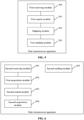
- FIG. 5 is a schematic diagram illustrating a structure of a data transmission apparatus according to embodiments of the present application.
- the apparatus includes a first search module 501 configured to abide by a mapping relationship between the resource configuration of a PUSCH resource and preamble sequence configuration information according to the resource configuration of the PUSCH resource and determine preamble sequence configuration information corresponding to the resource configuration of the PUSCH resource; a mapping module 502 configured to map a preamble sequence onto a PRACH resource according to the preamble sequence configuration information; and a first sending module 503 configured to send a message containing the PRACH resource and the PUSCH resource.
- information in the PUSCH resource includes at least one of a UE ID or user plane data.
- the apparatus may further include a first receiving module 504 configured to receive the mapping relationship between the resource configuration of the PUSCH resource and the preamble sequence configuration information, where the mapping relationship is sent by a base station.
- a first receiving module 504 configured to receive the mapping relationship between the resource configuration of the PUSCH resource and the preamble sequence configuration information, where the mapping relationship is sent by a base station.
- This embodiment can be applied to a UE.
- the mapping relationship between the resource configuration of the PUSCH resource and the preamble sequence configuration information in this embodiment is the same as that described in the preceding embodiments. The details are not repeated here.
- FIG. 6 is a schematic diagram illustrating a structure of a data transmission apparatus according to embodiments of the present application.
- the apparatus includes a second receiving module 601 configured to receive a message containing a PRACH resource and a PUSCH resource; a first acquisition module 602 configured to acquire the preamble sequence configuration information of the PRACH resource in the message; a second search module 603 configured to abide by a prestored mapping relationship between the resource configuration of the PUSCH resource and the preamble sequence configuration information according to the preamble sequence configuration information and determine the resource configuration mode of the PUSCH resource corresponding to the preamble sequence configuration information; and a second acquisition module 604 configured to acquire information in the PUSCH resource according to the resource configuration mode.
- the information in the PUSCH resource includes at least one of a UE ID or user plane data.
- the apparatus may further include a second sending module 605 configured to send theassociation rules between the resource configuration of the PUSCH resource and the preamble sequence configuration information to a UE to enable the UE to send the message according to the resource configuration of the PUSCH resource of the UE and the mapping relationship including the association rules
- This embodiment can be applied to a base station.
- the mapping relationship including the association rules between the resource configuration of the PUSCH resource and the preamble sequence configuration information in this embodiment is the same as that described in the preceding embodiments. The details are not repeated here.
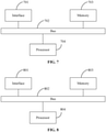
- FIG. 7 is a schematic diagram illustrating a structure of a UE for data transmission according to embodiments of the present application.
- the UE 70 of embodiments of the present application includes a memory 703 and a processor 704.
- the UE 70 may further include an interface 701 and a bus 702.
- the interface 701 and the memory 703 are connected to the processor 704 through the bus 702.
- the memory 703 is configured to store instructions.
- the processor 704 is configured to read the instructions to execute the technical solution of the preceding method embodiments applied to the UE.
- the implementation principles and technical effects are similar. The details are not repeated here.
- FIG. 8 is a schematic diagram illustrating a structure of a base station for data transmission according to embodiments of the present application.
- the base station 80 of embodiments of the present application includes a memory 803 and a processor 804.
- the base station 80 may further include an interface 801 and a bus 802.
- the interface 801 and the memory 803 are connected to the processor 804 through the bus 802.
- the memory 803 is configured to store instructions.
- the processor 804 is configured to read the instructions to execute the technical solution of the preceding method embodiments applied to the base station.
- the implementation principles and technical effects are similar. The details are not repeated here.
- FIG. 9 is a schematic diagram illustrating a structure of a communication system according to embodiments of the present application. As shown in FIG. 9 , the system includes the UE 70 and the base station 80 of the preceding embodiments.
- the present application provides a storage medium.
- the storage medium stores a computer program. When executed by a processor the computer program causes the processor to perform any method of the preceding embodiments.
- embodiments of the present application may be provided as methods, systems or computer program products. Therefore, the present application may take the form of a hardware embodiment, a software embodiment, or an embodiment combining software and hardware. Moreover, the present application may take the form of a computer program product implemented in one or more computer-usable storage media (including, but not limited to, a disk memory and an optical memory) that contain computer-usable program codes.
- a computer-usable storage media including, but not limited to, a disk memory and an optical memory
- each flow and/or block in the flowcharts and/or block diagrams and a combination of flows and/or blocks in the flowcharts and/or block diagrams may be implemented using computer program instructions.
- These computer program instructions may be provided for a processor of a general-purpose computer, special-purpose computer, embedded processor or another programmable data processing device to produce a machine so as to enable the instructions executed by the processor of the computer or another programmable data processing device to generate an apparatus for implementing the functions specified in one or more flows in the flowcharts and/or one or more blocks in the block diagrams.
- These computer program instructions may also be stored in a computer-readable memory that can direct a computer or another programmable data processing device to operate in a particular manner, so that the instructions stored in the computer-readable memory produce an article of manufacture including an instruction apparatus.
- the instruction apparatus implements the functions specified in one or more flows in the flowcharts and/or one or more blocks in the block diagrams.
- These computer program instructions may also be loaded onto a computer or another programmable data processing device so that a series of operating steps are performed on the computer or another programmable device, and thereby the instructions executed on the computer or another programmable device provide steps for implementing the functions specified in one or more flows in the flowcharts and/or one or more blocks in the block diagrams.
Landscapes
- Engineering & Computer Science (AREA)
- Signal Processing (AREA)
- Computer Networks & Wireless Communication (AREA)
- Physics & Mathematics (AREA)
- Mathematical Physics (AREA)
- Discrete Mathematics (AREA)
- General Physics & Mathematics (AREA)
- Mobile Radio Communication Systems (AREA)
Applications Claiming Priority (2)
| Application Number | Priority Date | Filing Date | Title |
|---|---|---|---|
| CN201910190286.7A CN110536418A (zh) | 2019-03-13 | 2019-03-13 | 数据传输方法、装置、用户设备、基站及存储介质 |
| PCT/CN2020/078802 WO2020182152A1 (zh) | 2019-03-13 | 2020-03-11 | 数据传输方法、装置、用户设备、基站、通信系统及存储介质 |
Publications (2)
| Publication Number | Publication Date |
|---|---|
| EP3941125A1 true EP3941125A1 (de) | 2022-01-19 |
| EP3941125A4 EP3941125A4 (de) | 2022-10-26 |
Family
ID=68659228
Family Applications (1)
| Application Number | Title | Priority Date | Filing Date |
|---|---|---|---|
| EP20769058.7A Pending EP3941125A4 (de) | 2019-03-13 | 2020-03-11 | Datenübertragungsverfahren und -vorrichtung, benutzergerät, basisstation, kommunikationssystem und speichermedium |
Country Status (5)
| Country | Link |
|---|---|
| US (2) | US12414108B2 (de) |
| EP (1) | EP3941125A4 (de) |
| KR (1) | KR102899490B1 (de) |
| CN (2) | CN110536418A (de) |
| WO (1) | WO2020182152A1 (de) |
Families Citing this family (15)
| Publication number | Priority date | Publication date | Assignee | Title |
|---|---|---|---|---|
| CN113330797B (zh) | 2019-01-11 | 2024-08-16 | 瑞典爱立信有限公司 | 用于免许可频谱中上行链路传输的资源分配 |
| CN111565471B (zh) * | 2019-02-14 | 2022-05-03 | 大唐移动通信设备有限公司 | 一种信息传输方法、装置及设备 |
| CN110536418A (zh) * | 2019-03-13 | 2019-12-03 | 中兴通讯股份有限公司 | 数据传输方法、装置、用户设备、基站及存储介质 |
| CN114342530A (zh) * | 2019-07-03 | 2022-04-12 | 瑞典爱立信有限公司 | 针对交错传输的频域资源分配 |
| KR102487216B1 (ko) * | 2019-10-04 | 2023-01-12 | 엘지전자 주식회사 | 무선 통신 시스템에서 단말이 임의 접속 과정을 수행하는 방법 및 이를 위한 장치 |
| US12294992B2 (en) | 2020-01-22 | 2025-05-06 | Lenovo (Beijing) Ltd. | Method and apparatus for MSGA transmission |
| CN111328152B (zh) * | 2020-02-27 | 2021-11-12 | 北京邮电大学 | 两步随机接入中MsgA的资源配置和传输方法 |
| CN113453351B (zh) * | 2020-03-27 | 2022-07-01 | 上海朗帛通信技术有限公司 | 一种被用于无线通信的节点中的方法和装置 |
| WO2021184179A1 (zh) * | 2020-03-17 | 2021-09-23 | Oppo广东移动通信有限公司 | 一种数据传输方法及装置、终端设备 |
| CN113453372B (zh) | 2020-03-25 | 2023-08-25 | 大唐移动通信设备有限公司 | 一种随机接入方法、基站、用户设备、装置、介质 |
| EP4133827A4 (de) * | 2020-04-08 | 2024-05-08 | Telefonaktiebolaget LM Ericsson (publ) | Verfahren und vorrichtung für direktzugriff |
| CN114007264B (zh) * | 2020-07-28 | 2025-09-12 | 大唐移动通信设备有限公司 | 一种数据传输方法、装置及存储介质 |
| WO2022061755A1 (en) * | 2020-09-25 | 2022-03-31 | Lenovo (Beijing) Limited | Methods and apparatuses for 2-step random access |
| KR102826044B1 (ko) * | 2023-06-23 | 2025-06-27 | 한국전자통신연구원 | 무선 통신 시스템에서 랜덤 액세스 프리앰블 및 상향링크 데이터 신호의 도달 영역 증대를 위한 장치 및 방법 |
| CN117956627A (zh) * | 2024-01-12 | 2024-04-30 | 中兴通讯股份有限公司 | 传输资源配置方法、通信装置及存储介质 |
Family Cites Families (18)
| Publication number | Priority date | Publication date | Assignee | Title |
|---|---|---|---|---|
| KR101447750B1 (ko) * | 2008-01-04 | 2014-10-06 | 엘지전자 주식회사 | 랜덤 액세스 과정을 수행하는 방법 |
| WO2014166046A1 (zh) | 2013-04-08 | 2014-10-16 | 华为技术有限公司 | 随机接入前导的发送与接收方法、以及相应的设备 |
| CN104254135B (zh) * | 2013-06-27 | 2020-03-31 | 夏普株式会社 | 基站和用户设备及其方法 |
| CN106465401B (zh) * | 2014-02-28 | 2019-09-10 | Lg电子株式会社 | 在无线通信系统中发送具有低延迟的上行链路数据的方法和设备 |
| CN104981022B (zh) * | 2014-04-04 | 2020-07-10 | 北京三星通信技术研究有限公司 | 数据传输的方法、基站及终端 |
| CN105848165B (zh) * | 2015-01-14 | 2022-01-18 | 中兴通讯股份有限公司 | 非授权资源的使用方法、系统、基站及用户设备 |
| US10231196B2 (en) * | 2015-04-10 | 2019-03-12 | Korea Advanced Institute Of Science And Technology | Communication apparatus and method using random access procedure |
| US11700641B2 (en) * | 2015-08-19 | 2023-07-11 | Lg Electronics Inc. | Random access procedure performing method in wireless communication system, and apparatus therefor |
| US10568081B2 (en) * | 2016-03-21 | 2020-02-18 | Samsung Electronics Co., Ltd. | Scheduling uplink transmissions |
| CN105979594B (zh) * | 2016-06-07 | 2019-07-05 | 北京邮电大学 | 一种基于资源分配的随机接入方法及装置 |
| US10425970B2 (en) * | 2016-09-30 | 2019-09-24 | Qualcomm Incorporated | Precoding management for random access procedures |
| CN108668361B (zh) * | 2017-04-01 | 2023-08-04 | 北京三星通信技术研究有限公司 | 一种信息生成方法和设备 |
| CN107371126B (zh) * | 2017-08-21 | 2019-07-30 | 西安电子科技大学 | 基于fdd-lte网络的随机接入方法 |
| CN111277382B (zh) * | 2019-01-18 | 2021-10-22 | 维沃移动通信有限公司 | 一种随机接入过程的信息传输方法及终端 |
| US11032854B2 (en) * | 2019-01-18 | 2021-06-08 | Qualcomm Incorporated | Variable payload size for two-step random access |
| CN111565471B (zh) * | 2019-02-14 | 2022-05-03 | 大唐移动通信设备有限公司 | 一种信息传输方法、装置及设备 |
| CN115843116A (zh) * | 2019-02-15 | 2023-03-24 | 华为技术有限公司 | 一种随机接入方法、设备及系统 |
| CN110536418A (zh) | 2019-03-13 | 2019-12-03 | 中兴通讯股份有限公司 | 数据传输方法、装置、用户设备、基站及存储介质 |
-
2019
- 2019-03-13 CN CN201910190286.7A patent/CN110536418A/zh active Pending
- 2019-03-13 CN CN202210337205.3A patent/CN114786256B/zh active Active
-
2020
- 2020-03-11 EP EP20769058.7A patent/EP3941125A4/de active Pending
- 2020-03-11 KR KR1020217029458A patent/KR102899490B1/ko active Active
- 2020-03-11 WO PCT/CN2020/078802 patent/WO2020182152A1/zh not_active Ceased
-
2021
- 2021-09-10 US US17/472,283 patent/US12414108B2/en active Active
-
2025
- 2025-09-08 US US19/322,353 patent/US20260006608A1/en active Pending
Also Published As
| Publication number | Publication date |
|---|---|
| KR20210151063A (ko) | 2021-12-13 |
| CN114786256A (zh) | 2022-07-22 |
| WO2020182152A1 (zh) | 2020-09-17 |
| US20260006608A1 (en) | 2026-01-01 |
| US20220104226A1 (en) | 2022-03-31 |
| CN114786256B (zh) | 2026-03-13 |
| KR102899490B1 (ko) | 2025-12-11 |
| EP3941125A4 (de) | 2022-10-26 |
| CN110536418A (zh) | 2019-12-03 |
| US12414108B2 (en) | 2025-09-09 |
Similar Documents
| Publication | Publication Date | Title |
|---|---|---|
| EP3941125A1 (de) | Datenübertragungsverfahren und -vorrichtung, benutzergerät, basisstation, kommunikationssystem und speichermedium | |
| CN110582952B (zh) | 用于无线通信系统中发送和接收控制信道的方法、装置和系统 | |
| EP4307581B1 (de) | Verfahren und vorrichtung zur übertragung eines messreferenzsignals | |
| US10912038B2 (en) | Uplink scheduling method and apparatus | |
| US11057942B2 (en) | Data transmission method for multiplexing data portion, device, and system | |
| CA2717602C (en) | Method and apparatus for mapping virtual resources to physical resources in a wireless communication system | |
| US10523372B2 (en) | Method and apparatus for the transmission of uplink control information | |
| EP4017180B1 (de) | Kommunikationsverfahren und -vorrichtung | |
| EP3748888B1 (de) | Informationsübertragungsverfahren und -vorrichtung sowie speichermedium und elektronische vorrichtung | |
| EP3614758A1 (de) | Ressourcenplanungsverfahren, endgerätevorrichtung und netzwerkvorrichtung | |
| EP3148242A1 (de) | Datenübertragungsverfahren und -vorrichtung | |
| WO2020220306A1 (en) | Resource indication in random access | |
| US20200021388A1 (en) | Data Sending Method and Apparatus and Data Receiving Method and Apparatus | |
| CN105897373A (zh) | 一种在下行控制信道传送传输块的方法和系统 | |
| CN103220690A (zh) | 下行控制信息的发送、下行控制信道的检测方法及装置 | |
| EP3557791A1 (de) | Datenübertragungsverfahren, sender, empfänger und speichermedium | |
| US20200383139A1 (en) | Method and device for sending and receiving preamble sequence of physical random access channel | |
| US20200359364A1 (en) | Channel transmission method and apparatus | |
| EP3522416B1 (de) | Verfahren, vorrichtung und system zur verarbeitung von rückmeldungen sowie basisstation und endgerät | |
| EP3373674A1 (de) | Datenverarbeitungsverfahren und -vorrichtung | |
| US20240089060A1 (en) | Reference signal port indication techniques | |
| CN110536270B (zh) | 数据发送、接收方法、装置、终端、基站及存储介质 | |
| US8238295B2 (en) | Demodulation of a subset of available link assignment blocks | |
| WO2017121416A1 (zh) | 上行控制信息的发送方法及装置 | |
| CN116939521A (zh) | 一种传输方法、电子设备和存储介质 |
Legal Events
| Date | Code | Title | Description |
|---|---|---|---|
| STAA | Information on the status of an ep patent application or granted ep patent |
Free format text: STATUS: THE INTERNATIONAL PUBLICATION HAS BEEN MADE |
|
| PUAI | Public reference made under article 153(3) epc to a published international application that has entered the european phase |
Free format text: ORIGINAL CODE: 0009012 |
|
| STAA | Information on the status of an ep patent application or granted ep patent |
Free format text: STATUS: REQUEST FOR EXAMINATION WAS MADE |
|
| 17P | Request for examination filed |
Effective date: 20211012 |
|
| AK | Designated contracting states |
Kind code of ref document: A1 Designated state(s): AL AT BE BG CH CY CZ DE DK EE ES FI FR GB GR HR HU IE IS IT LI LT LU LV MC MK MT NL NO PL PT RO RS SE SI SK SM TR |
|
| DAV | Request for validation of the european patent (deleted) | ||
| DAX | Request for extension of the european patent (deleted) | ||
| REG | Reference to a national code |
Ref country code: DE Ref legal event code: R079 Free format text: PREVIOUS MAIN CLASS: H04W0072020000 Ipc: H04L0005000000 |
|
| A4 | Supplementary search report drawn up and despatched |
Effective date: 20220928 |
|
| RIC1 | Information provided on ipc code assigned before grant |
Ipc: H04W 74/08 20090101ALI20220922BHEP Ipc: H04L 5/00 20060101AFI20220922BHEP |
|
| RAP3 | Party data changed (applicant data changed or rights of an application transferred) |
Owner name: ZTE CORPORATION |
|
| STAA | Information on the status of an ep patent application or granted ep patent |
Free format text: STATUS: EXAMINATION IS IN PROGRESS |
|
| 17Q | First examination report despatched |
Effective date: 20231212 |