EP3942205B1 - Flussbegrenzungsvorrichtungen, verfahren und systeme - Google Patents
Flussbegrenzungsvorrichtungen, verfahren und systeme Download PDFInfo
- Publication number
- EP3942205B1 EP3942205B1 EP20778728.4A EP20778728A EP3942205B1 EP 3942205 B1 EP3942205 B1 EP 3942205B1 EP 20778728 A EP20778728 A EP 20778728A EP 3942205 B1 EP3942205 B1 EP 3942205B1
- Authority
- EP
- European Patent Office
- Prior art keywords
- tube
- lever element
- free lever
- pinching
- linear actuator
- Prior art date
- Legal status (The legal status is an assumption and is not a legal conclusion. Google has not performed a legal analysis and makes no representation as to the accuracy of the status listed.)
- Active
Links
Images


Classifications
-
- F—MECHANICAL ENGINEERING; LIGHTING; HEATING; WEAPONS; BLASTING
- F04—POSITIVE - DISPLACEMENT MACHINES FOR LIQUIDS; PUMPS FOR LIQUIDS OR ELASTIC FLUIDS
- F04B—POSITIVE-DISPLACEMENT MACHINES FOR LIQUIDS; PUMPS
- F04B43/00—Machines, pumps, or pumping installations having flexible working members
- F04B43/0009—Special features
- F04B43/0081—Special features systems, control, safety measures
-
- A—HUMAN NECESSITIES
- A61—MEDICAL OR VETERINARY SCIENCE; HYGIENE
- A61M—DEVICES FOR INTRODUCING MEDIA INTO, OR ONTO, THE BODY; DEVICES FOR TRANSDUCING BODY MEDIA OR FOR TAKING MEDIA FROM THE BODY; DEVICES FOR PRODUCING OR ENDING SLEEP OR STUPOR
- A61M5/00—Devices for bringing media into the body in a subcutaneous, intra-vascular or intramuscular way; Accessories therefor, e.g. filling or cleaning devices, arm-rests
- A61M5/14—Infusion devices, e.g. infusing by gravity; Blood infusion; Accessories therefor
- A61M5/168—Means for controlling media flow to the body or for metering media to the body, e.g. drip meters, counters ; Monitoring media flow to the body
- A61M5/16804—Flow controllers
- A61M5/16813—Flow controllers by controlling the degree of opening of the flow line
-
- A—HUMAN NECESSITIES
- A61—MEDICAL OR VETERINARY SCIENCE; HYGIENE
- A61M—DEVICES FOR INTRODUCING MEDIA INTO, OR ONTO, THE BODY; DEVICES FOR TRANSDUCING BODY MEDIA OR FOR TAKING MEDIA FROM THE BODY; DEVICES FOR PRODUCING OR ENDING SLEEP OR STUPOR
- A61M5/00—Devices for bringing media into the body in a subcutaneous, intra-vascular or intramuscular way; Accessories therefor, e.g. filling or cleaning devices, arm-rests
- A61M5/14—Infusion devices, e.g. infusing by gravity; Blood infusion; Accessories therefor
- A61M5/168—Means for controlling media flow to the body or for metering media to the body, e.g. drip meters, counters ; Monitoring media flow to the body
- A61M5/16877—Adjusting flow; Devices for setting a flow rate
-
- F—MECHANICAL ENGINEERING; LIGHTING; HEATING; WEAPONS; BLASTING
- F16—ENGINEERING ELEMENTS AND UNITS; GENERAL MEASURES FOR PRODUCING AND MAINTAINING EFFECTIVE FUNCTIONING OF MACHINES OR INSTALLATIONS; THERMAL INSULATION IN GENERAL
- F16K—VALVES; TAPS; COCKS; ACTUATING-FLOATS; DEVICES FOR VENTING OR AERATING
- F16K7/00—Diaphragm valves or cut-off apparatus, e.g. with a member deformed, but not moved bodily, to close the passage ; Pinch valves
- F16K7/02—Diaphragm valves or cut-off apparatus, e.g. with a member deformed, but not moved bodily, to close the passage ; Pinch valves with tubular diaphragm
- F16K7/04—Diaphragm valves or cut-off apparatus, e.g. with a member deformed, but not moved bodily, to close the passage ; Pinch valves with tubular diaphragm constrictable by external radial force
- F16K7/06—Diaphragm valves or cut-off apparatus, e.g. with a member deformed, but not moved bodily, to close the passage ; Pinch valves with tubular diaphragm constrictable by external radial force by means of a screw-spindle, cam, or other mechanical means
Definitions
- a variable flow restrictor comprising: a tube support having a hollow and holding a flexible tube; a free rod element trapped in the hollow, the free rod element having a pinching end and a driven end; and a linear actuator having a rod which can move in a linear direction and has at is end an end effecter which is configured to push the driven end of the free rod element progressively such that the free rod element moves linearly and the pinching end of the free rod element progressively pinches the tube against a first wall of said hollow, wherein the hollow has second and third walls and the free rod element is a longitudinal member and the linear actuator is configured to push the driven end of the free rod element such that said driven end rides along the third wall while a middle of rod element slides along the second wall.
- a flow mixing system having variable flow restrictors is known.
- variable pinch valve provides precise flow control by progressively pinching a tube.
- the pinching element creates a gradually-increasing mechanical advantage that increases the force pinching the tube as the tube approaches full occlusion.
- a system having inventive variable flow restrictors can serve as a basis for a flow regulation system in which the variable pinch valves each controls the flow of a separate fluid.
- the fluids may be combined to form a mixture.
- Each fluid may be driven by a hydraulic source fluid which feeds a flexible-walled isolation element so the hydraulic source fluid does not mix with the separate fluids.
- the ratio of volumes of the separate fluids may be determined by the variable pinch valves and a relative flow therethrough.
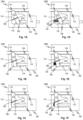
- a tube support 100A has a hollow 108 that confines a free lever element 111.
- a tube 112 is held by a tube support 124.
- Free lever element 111 progressively pinches the tube 112 by pushing a pinching end 110 of the free lever element 111 into the tube 112 as an opposite driven end 106 of the free lever element 111 is pushed, by an end effecter 120 of a linear actuator 104, along a wall 116 causing the pinching end 110 to slide along a wall 114.
- the linear actuator 104 has a rod 102 which can move in a linear direction (horizontal direction in Figs.
- the rod 102 has at its end the end effecter 120, which is positioned to press on free lever element 111.
- the linear actuator 104 pushes the free lever element 111 so that it pivots and such that its pinching end 110 is driven into the side of the tube 112 thereby pinching it progressively closed.
- This motion creates a gradually-increasing mechanical advantage that increases the force pinching the tube 112 as the tube 112 approaches full occlusion.
- the displacement of the linear actuator 104 thereby determines the amount by which the tube 112 is pinched and thereby determines the cross-sectional area of the inside of the tube 112. This gradually changes the magnitude of a flow restriction represented by the tube 112.
- the engagement of the free lever with the walls 114 and 114 may be identified as joints, namely, sliding joints. Their engagement may also be identified as revolute joints.
- an equivalent kinematic mechanism may be provided where the free lever is a link, through revolute joints, two sliding joints at the end of the free lever.
- Fig. 1A the free lever element 111 is shown pinching the tube 112 to a small degree.
- Fig. 1B the free lever element 111 is shown pinching the tube 112 to a larger degree.
- Fig. 1C the free lever element 111 is shown pinching the tube 112 to a maximal degree, effectively fully occluding the tube 112 to prevent any flow therethrough.
- a spring 125 may be provided to return the free lever element 111 to a non-occluding or lower-occluding position. That is, the linear actuator 104 pushes the end effecter 120 into the opposite driven end 106, a side of the free lever element 111 is pushed against and compresses the spring 125.
- the spring may be partially recessed in the wall 114 as illustrated.
- a secondary function of the spring 125 is to prevent backlash.
- springs may be provided such as leaf springs and this applies to any of the embodiments described or claimed.
- the spring 125 may be a tension spring with the function of preventing backlash in the linear actuator 104.
- the free lever element 111 is shown pinching the tube 112 to a small degree.
- the free lever element 111 is shown pinching the tube 112 to a larger degree.
- the free lever element 111 is shown pinching the tube 112 to a maximal degree, effectively fully occluding the tube 112 to prevent any flow therethrough.
- the linear actuator withdraws by moving in progression shown by the sequence of Figs. 1F, 1E , to 1D
- the spring 125 pushes the free lever element opposite driven end 106 back along with the end effecter 120 following it backwards and withdrawing the pinching end of the free lever element away from the tube 112 thereby allowing the tube to relax.
- the internal area of the tube 112 expands allowing progressively more flow.
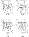
- another tube support 100C has a dual-action pinching mechanism.
- the pinching end 170 of a distal element 160 carries a roller 162.
- the distal element 160 is a link (and will also be referred to as link 160) connected to an intermediate link 154 by a revolute joint 171.
- the intermediate link 154 is connected to the effecter 152 of a linear actuator 150 by a revolute joint 173.
- Rollers 158 and 156 allow the revolute joints 171 and 173 to roll along the walls 164 and 166 of hollow 168, respectively.
- the tube 112 is held by tube support 124.
- the dual action motion of the link 154 generates a progressively-increasing mechanical advantage that increases the force pinching the tube 112 as the tube 112 approaches full occlusion.
- the linear actuator 150 extend withdraws the effecter 152 pulling the intermediate link 154 downwardly and forcing the roller 158 and the revolute joint 171 along the wall 164 thereby driving the roller 162 into the tube 112.
- the tube 112 is shown fully occluded in Fig. 2B and partially occluded in Fig. 2A .
- the linear actuator 150 may restore the links 154 and 160 to their non-occluding position due to the connection by the revolute joint 173 at the end of the effecter 152. That is, as the linear actuator 150 extends the effecter 152, the revolute joint 173 is pushed away from the linear actuator 150 causing the roller 156 to roll along the wall 166 and thereby causing the roller 158 to roll along wall 164 taking the revolute joint 171 with it.
- a spring 165 may be provided to reduce the force required to return the links 154 and 160. Such an embodiment is shown in Figs. 2C and 2D .
- the spring 165 pushes the joint 171 away from the wall 166 to assist in causing the roller 162 to retract from the tube 112.
- spring 165 may be a tension or compression spring. The function of the spring is to prevent backlash in the linear actuator 150.
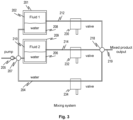
- a system employs multiple variable flow restrictors 230 to 234 to regulate, independently, flows of first fluid 202, second fluid 210 and water from second bag 206.
- a first fluid 202 is held in a bag in a confining container 201 with a second bag containing water 208 such that when water is pumped into the second bag 208, the first fluid 202 is forced out through a line 212 regulated by a variable flow restrictor 230.
- a second fluid 210 is held in a bag in a confining container 209 with a second bag containing water 206 such that when water is pumped into the second bag 206, the second fluid 210 is forced out through a line 214 regulated by a variable flow restrictor 232.
- variable flow restrictor 234 The water from line 204 and the fluid in lines 212 and 214 may be mixed in a mixing unit 218 to produce a mixture at 219.
- the variable flow restrictors may be as described according to any of foregoing embodiments including 100A through 100D.
- FIG. 4A and 4B a further pinching mechanism configuration is shown.
- a pair of legs 302 and 304 are joined at a hinge with a roller 308 such that when one leg 304 is pushed toward the other, the roller 308 is pushed into the tube squeezing it closed. It will be observed that the force of the roller 308 rises with displacement of the leg 304 toward a maximum value in the position shown in Fig. 4B .
- a linear actuator 316 having an end effecter 318 pushes the leg 304 toward the leg 302. Roller 308 rolls along the tube 314 thereby squeezing the tube 314 closed as shown in Fig. 4B .
- a two-part tube support with pressure relief blocks 324 and 326 and spring 328 may be used to limit the amount of force that is applied to the tube 314. Rollers 310 and 312 roll along the recess 322. A leaf spring 320 prevents any backlash of the linear actuator 316 and the end effecter 318 by continuously applying a restoring force to the leg 304.
- the recess 322 is defined within a frame 330.
- a lever element 427A is driven by an end effecter 318 moved by a linear actuator 316.
- the lever element 427B is similarly driven by the end effector at its end.
- the lever element 427B releases pressure on a tube 314B while lever element 417B increase pressure on the tube 314A.
- the tubes are oppositely squeezed for a given motion of the end effecter.
- each tube is forced against a respective stop 426.
- Each lever element rides an internal surface 430 of a respective block element 445.
- the tube 314B is shown being released by the lever element 427B and in Fig.
- the same tube 314B is shown being squeezed.
- the tube 314B is shown squeezed by the lever element 427B and in Fig. 5B the same tube 314B is shown being released.
- the tubes can be ratiometrically pinched by the lever elements which are driven by a single linear actuator.
- a flow restrictor 459 has constraints, except for the linear actuator, that are all provided by links with revolute joints.
- a tube 462 is only slightly pinched by a pinching effecter 454.
- the pinching effecter 454 is guided or constrained by a link 461 connected to a chassis portion 470 by a revolute joint 460.
- Chassis portion 470 may be fixedly connected to all the chassis portions 468, 466, and 464 to fixedly support all revolute joints 460, 452, and 458 as well as tube 462.
- All the chassis portions may be parts of the same component such that none of them moves with respect to the others when the flow restrictor 459 is actuated to pinch the tube 462.
- the linear actuator 456 is supported on a revolute joint 458.
- the effecter 472 pushes on a pair of concentric revolute joints centered at 450 to drive links 474 and 476 to make the angle between them more or less obtuse depending on the direction of movement of the linear actuator 456.
- pinching effecter 454 may revolve around revolute joint 453 or not. That is, the pinching effecter 454 may be fixedly attached to link 461 or 476 or it can revolve around the revolute joint 453 instead. Comparing Fig. 6A with Fig. 6B illustrates the operation of the mechanism shown and makes clear that only revolute joints, apart from the linear actuator, are required to push the pinching effecter 454 into the tube in the manner whereby the mechanical advantage increases as the tube is increasingly pinched.
- An aspect common to embodiments disclosed herein includes the non-linearity of the relationship between pinching force delivered to the tube and the displacement of the linear actuator.
- the pinching force the valve is capable of delivering for a given size motor increases as the linear actuator is displaced. This provides a benefit in that it takes more force to close a tube close to full occlusion than it takes to close it initially.
- Another aspect common to embodiments disclosed herein is that the non-linear relationship between displacement of the motor and deformation of the walls of the tube by the part of the valve in contact with the tube which actually deforms it to reduce the flow.
- This is beneficial because for a given pressure, the relationship between the rate of flow and the deformation of the tube is also non-linear. That is, the flow rate drops less and less for each increment of displacement of the walls of the tube as the tube is pinched such that at the beginning of a closure, very little reduction in flow occurs and at the end of the closure a larger reduction in flow occurs.
- linkages transfer force of the linear motor to a final element that pinches a tube
- the linkages collectively, will be understood to be a force transfer mechanism, a kinematic chain, a transmission, or other similar identifier of its function.
- Any sliding constraint may be identified as a joint, namely a sliding joint.
- the disclosed subject matter includes a variable flow restrictor with a tube support having a hollow with a flexible tube therein.
- a free lever element is trapped in the hollow.
- An actuator is configured to push the free lever element progressively such that it progressively pinches the tube against a first wall of said hollow.
- the foregoing embodiments includes ones in which the free lever element is a longitudinal member. In variations thereof, the foregoing embodiments includes ones in which the actuator is configured to push the free lever element such that an end thereof rides along second wall of said hollow. In variations thereof, the foregoing embodiments includes ones in which the free lever element is a longitudinal member and the actuator is configured to push one end thereof such that another end thereof rides along a second wall of said hollow. In variations thereof, the foregoing embodiments includes ones in which the hollow has second and third walls and the free lever element is a longitudinal member and the actuator is configured to push one end thereof such that said one end rides along the third wall while another end thereof rides along the second wall.
- the foregoing embodiments includes ones in which the actuator has first and second links connected by a revolute joint, a distal one of which is connected by a further revolute joint to the lever element. In variations thereof, the foregoing embodiments includes ones in which wheels are attached at each of the revolute joints. In variations thereof, the foregoing embodiments includes ones in which the first, second, and third walls are straight. In variations thereof, the foregoing embodiments includes ones in which the first link is connected to a linear actuator.
- the foregoing embodiments includes ones in which the free lever element is forced by a return spring.
- the disclosed subject matter includes a variable flow restrictor with a tube support having a hollow with a flexible tube therein.
- a free lever element is trapped in the hollow.
- An actuator is configured to push the free lever element progressively such that it progressively pinches the tube against a first wall of said hollow.
- the free lever element is a longitudinal member.
- the actuator is configured to push the free lever element such that an end thereof rides along second wall of said hollow.
- the free lever element is a longitudinal member and the actuator is configured to push one end thereof such that another end thereof rides along a second wall of said hollow.
- the hollow has second and third walls and the free lever element is a longitudinal member and the actuator is configured to push one end thereof such that said one end rides along the third wall while another end thereof rides along the second wall.
- the actuator has first and second links connected by a revolute joint, a distal one of which is connected by a further revolute joint to the lever element.
- wheels are attached at each of the revolute joints.
- the first, second, and third walls are straight.
- the first link is connected to a linear actuator.
- the free lever element is forced by a return spring.
Landscapes
- Health & Medical Sciences (AREA)
- Engineering & Computer Science (AREA)
- General Engineering & Computer Science (AREA)
- Hematology (AREA)
- Animal Behavior & Ethology (AREA)
- Anesthesiology (AREA)
- Biomedical Technology (AREA)
- Heart & Thoracic Surgery (AREA)
- Veterinary Medicine (AREA)
- Life Sciences & Earth Sciences (AREA)
- Vascular Medicine (AREA)
- General Health & Medical Sciences (AREA)
- Public Health (AREA)
- Mechanical Engineering (AREA)
- Physics & Mathematics (AREA)
- Fluid Mechanics (AREA)
- Infusion, Injection, And Reservoir Apparatuses (AREA)
Claims (6)
- Variabler Durchflussbegrenzer (100A, 100B, 100C, 100D), aufweisend:einen Rohrträger (124), aufweisend einen Hohlraum (108, 168) und konfiguriert, um ein flexibles Rohr (112) zu halten,ein freies Hebelelement (111, 160), das in dem Hohlraum (108, 168) eingeschlossen ist, wobei das freie Hebelelement (111, 160) ein Einklemm-Ende (110, 170) und ein angetriebenes Ende (106) aufweist, undeinen Linearaktuator (104, 150), aufweisend eine Stange (102, 152), die sich in einer linearen Richtung bewegen kann und an ihrem Ende einen Endeffektor (120) aufweist, der konfiguriert ist, um das angetriebene Ende (106) des freien Hebelelements (111) fortschreitend zu schieben, so dass das freie Hebelelement (111, 160) geschwenkt wird und das Klemm-Ende (110, 170) des freien Hebelelements (111, 160) konfiguriert ist, um das flexible Rohr (112) fortschreitend gegen eine erste Wand des Hohlraums zu klemmen, um dadurch im Gebrauch das flexible Rohr (112) fortschreitend zu schließen,wobei der Hohlraum (108, 168) eine zweite (114, 166) und dritte (116, 164) Wand hat und das freie Hebelelement (111, 160) ein Längselement ist und der Linearaktuator (104, 150) konfiguriert ist, um das angetriebene Ende (106) des freien Hebelelements (111, 160) so zu schieben, dass das angetriebene Ende (106) sich entlang der dritten Wand (116, 164) bewegt, während das Klemm-Ende (110, 170) entlang der zweiten Wand (114, 166) gleitet.
- Durchflussbegrenzer gemäß Anspruch 1, wobei der Aktuator (150) ein erstes (152) und ein zweites (154) Verbindungsstück aufweist, die durch ein Drehgelenk (173) verbunden sind, von denen ein distales (154) durch ein weiteres Drehgelenk (171) mit dem freien Hebelelement (160) verbunden ist.
- Durchflussbegrenzer gemäß Anspruch 2, wobei an jedem der Drehgelenke Rollen (156, 158) angebracht sind.
- Durchflussbegrenzer gemäß Anspruch 1, wobei die erste, zweite (114, 166) und dritte (116, 164) Wand gerade sind.
- Durchflussbegrenzer gemäß Anspruch 2, wobei das erste Verbindungsstück (152) mit dem Linearaktuator (150) verbunden ist.
- Durchflussbegrenzer gemäß Anspruch 1, wobei das freie Hebelelement (111, 160) durch eine Rückstellfeder (125, 165) vorgespannt ist.
Applications Claiming Priority (3)
| Application Number | Priority Date | Filing Date | Title |
|---|---|---|---|
| US201962822117P | 2019-03-22 | 2019-03-22 | |
| US201962937907P | 2019-11-20 | 2019-11-20 | |
| PCT/US2020/023924 WO2020198030A1 (en) | 2019-03-22 | 2020-03-20 | Flow restriction devices, methods, and systems |
Publications (3)
| Publication Number | Publication Date |
|---|---|
| EP3942205A1 EP3942205A1 (de) | 2022-01-26 |
| EP3942205A4 EP3942205A4 (de) | 2022-12-07 |
| EP3942205B1 true EP3942205B1 (de) | 2025-04-23 |
Family
ID=72610004
Family Applications (1)
| Application Number | Title | Priority Date | Filing Date |
|---|---|---|---|
| EP20778728.4A Active EP3942205B1 (de) | 2019-03-22 | 2020-03-20 | Flussbegrenzungsvorrichtungen, verfahren und systeme |
Country Status (3)
| Country | Link |
|---|---|
| US (2) | US12017042B2 (de) |
| EP (1) | EP3942205B1 (de) |
| WO (1) | WO2020198030A1 (de) |
Families Citing this family (1)
| Publication number | Priority date | Publication date | Assignee | Title |
|---|---|---|---|---|
| JP2025042069A (ja) * | 2023-09-14 | 2025-03-27 | シナノケンシ株式会社 | ピンチバルブ装置 |
Family Cites Families (28)
| Publication number | Priority date | Publication date | Assignee | Title |
|---|---|---|---|---|
| US2010229A (en) * | 1935-06-10 | 1935-08-06 | George B Goff | Hose clamp |
| US2183835A (en) * | 1938-02-25 | 1939-12-19 | Du Pont | Valve |
| US2527614A (en) * | 1948-01-29 | 1950-10-31 | Arpin John William | Water pistol |
| US3156444A (en) * | 1961-12-11 | 1964-11-10 | Douglas E Black | Pipe squeezing apparatus for controlling flow through plastic pipe |
| US3335753A (en) * | 1964-03-02 | 1967-08-15 | Kiser Ohlmann Inc | Control valve with adjustable flow rate, especially for dispensing machines |
| US3308898A (en) * | 1965-09-22 | 1967-03-14 | Harper Inc Allen | Vibrated flow control valve and weigher |
| US3515367A (en) * | 1967-09-13 | 1970-06-02 | Ziaylek Theodore Jun | Hose clamp |
| US3759483A (en) * | 1971-05-14 | 1973-09-18 | T Baxter | Fluid actuated control valve |
| US3930761A (en) * | 1972-12-19 | 1976-01-06 | The Boots Company, Ltd. | Portable and manually operable peristaltic pump |
| US3861421A (en) * | 1974-01-11 | 1975-01-21 | Emco Ltd | Pinch tube faucet |
| US4077601A (en) * | 1976-12-13 | 1978-03-07 | Dick George M | Adjustable pinch clamp |
| IT1084192B (it) * | 1977-08-30 | 1985-05-25 | Selman Di Crespi Carlo & Ferra | Dispositivo dosatore per pasta dentifricia o altro materiale pastoso |
| JPS6018398Y2 (ja) | 1979-10-19 | 1985-06-04 | 株式会社吉野工業所 | 液体容器の注出器 |
| US4323219A (en) * | 1980-05-19 | 1982-04-06 | Carlin Jack M | Automatic hose clamp |
| US4372345A (en) | 1981-07-13 | 1983-02-08 | Economics Laboratory, Inc. | Fail-safe valve |
| HU186147B (en) | 1982-10-26 | 1985-06-28 | Mueszeripari Muevek Lab | Bistable selector valve |
| US5191881A (en) | 1991-01-28 | 1993-03-09 | Genesis Medical, Ltd. | Insufflating/suctioning valve |
| FR2680995B1 (fr) * | 1991-09-10 | 1995-07-13 | Gaz De France | Pince et application de cette pince pour l'ecrasement d'une canalisation, telle qu'une conduite de gaz. |
| US5588634A (en) * | 1995-12-11 | 1996-12-31 | Megadyne Medical Products, Inc. | Fluid flow control device pinch mechanism |
| US5896887A (en) * | 1997-06-19 | 1999-04-27 | George S. Cole & Associates, Incorporated | Pinch tube tank level control valve with snap-action shutoff |
| ATE314596T1 (de) * | 2000-07-11 | 2006-01-15 | Arno Drechsel | Ventil |
| US7303175B2 (en) * | 2004-07-16 | 2007-12-04 | Cardinal Health 303, Inc. | Automatic clamp apparatus having lateral motion resistance for IV infusion sets |
| US20090270844A1 (en) | 2008-04-24 | 2009-10-29 | Medtronic, Inc. | Flow sensor controlled infusion device |
| US8387655B2 (en) | 2009-06-12 | 2013-03-05 | Kelly Cowlishaw | Slurry flow control device |
| WO2012014267A1 (ja) | 2010-07-26 | 2012-02-02 | スーガン株式会社 | バルブ付ハンドスイッチおよび薬液導入システム |
| CN104415422A (zh) * | 2013-09-06 | 2015-03-18 | 中山市玫瑰园环境电器有限公司 | 输液流量控制器 |
| CN104415424A (zh) * | 2013-09-06 | 2015-03-18 | 中山市玫瑰园环境电器有限公司 | 输液控制器 |
| CN109357038A (zh) | 2018-11-29 | 2019-02-19 | 珠海优特智厨科技有限公司 | 夹管机构 |
-
2020
- 2020-03-20 EP EP20778728.4A patent/EP3942205B1/de active Active
- 2020-03-20 US US17/441,919 patent/US12017042B2/en active Active
- 2020-03-20 WO PCT/US2020/023924 patent/WO2020198030A1/en not_active Ceased
-
2024
- 2024-05-29 US US18/676,776 patent/US20240307616A1/en active Pending
Also Published As
| Publication number | Publication date |
|---|---|
| US20220143310A1 (en) | 2022-05-12 |
| US20240307616A1 (en) | 2024-09-19 |
| EP3942205A4 (de) | 2022-12-07 |
| WO2020198030A1 (en) | 2020-10-01 |
| EP3942205A1 (de) | 2022-01-26 |
| US12017042B2 (en) | 2024-06-25 |
Similar Documents
| Publication | Publication Date | Title |
|---|---|---|
| US10556059B2 (en) | Infusion pump drive with compression spring | |
| US5957889A (en) | Displacement system for controlled infusion of a liquid | |
| DE60203075T2 (de) | Universalrohrklemmaufbau | |
| US20240307616A1 (en) | Flow Restriction Devices, Methods, and Systems | |
| EP0721358B1 (de) | Fördersystem zur geregelten infusion einer flüssigkeit | |
| EP0830533B1 (de) | Ventilsatz | |
| US4561830A (en) | Linear peristaltic pump | |
| EP2510234B1 (de) | Kontinuierlich fördernde infusionspumpe | |
| EP2568178B1 (de) | Pumpvorrichtung | |
| MX2011009516A (es) | Bomba de infusion peristaltica que tiene un mecanismo para reformar el tubo flexible. | |
| JP2013516234A (ja) | 制御されたチューブの変形を有している蠕動ポンプ | |
| EP1771117B1 (de) | Medizinische pumpe | |
| RU2707169C2 (ru) | Сцепная муфта гидрораспределителя и содержащее ее дозирующее устройство | |
| US20190290842A1 (en) | Dual Latching Microvalves | |
| DE102011119591B3 (de) | Prothese mit einer peristaltischen Pumpe | |
| EP3630225A1 (de) | Infusionspumpe mit einem verschiedene betriebszustände einnehmbaren pumpmodul | |
| EP4137174B1 (de) | Infusionsbox einer infusionsvorrichtung, infusionsvorrichtung und infusionspumpe | |
| US11890451B2 (en) | Anti-free-flow valve | |
| JP2010519482A5 (de) | ||
| EP4653709A1 (de) | Ventilanordnung | |
| DE102009043245B4 (de) | Schlauchpumpe | |
| EP4534122A1 (de) | Dosiervorrichtung für medizinische flüssigkeiten | |
| RU2054951C1 (ru) | Устройство для внутривенного вливания жидкости | |
| US3587636A (en) | Variable displacement pumps | |
| HK1234124A1 (en) | Dual latching microvalves |
Legal Events
| Date | Code | Title | Description |
|---|---|---|---|
| STAA | Information on the status of an ep patent application or granted ep patent |
Free format text: STATUS: THE INTERNATIONAL PUBLICATION HAS BEEN MADE |
|
| PUAI | Public reference made under article 153(3) epc to a published international application that has entered the european phase |
Free format text: ORIGINAL CODE: 0009012 |
|
| STAA | Information on the status of an ep patent application or granted ep patent |
Free format text: STATUS: REQUEST FOR EXAMINATION WAS MADE |
|
| 17P | Request for examination filed |
Effective date: 20210907 |
|
| AK | Designated contracting states |
Kind code of ref document: A1 Designated state(s): AL AT BE BG CH CY CZ DE DK EE ES FI FR GB GR HR HU IE IS IT LI LT LU LV MC MK MT NL NO PL PT RO RS SE SI SK SM TR |
|
| DAV | Request for validation of the european patent (deleted) | ||
| DAX | Request for extension of the european patent (deleted) | ||
| A4 | Supplementary search report drawn up and despatched |
Effective date: 20221108 |
|
| RIC1 | Information provided on ipc code assigned before grant |
Ipc: F04B 43/00 20060101ALI20221102BHEP Ipc: F04B 43/08 20060101ALI20221102BHEP Ipc: A61M 5/168 20060101ALI20221102BHEP Ipc: A61M 5/145 20060101ALI20221102BHEP Ipc: A61M 5/142 20060101ALI20221102BHEP Ipc: A61B 1/015 20060101ALI20221102BHEP Ipc: F16K 7/06 20060101AFI20221102BHEP |
|
| GRAP | Despatch of communication of intention to grant a patent |
Free format text: ORIGINAL CODE: EPIDOSNIGR1 |
|
| STAA | Information on the status of an ep patent application or granted ep patent |
Free format text: STATUS: GRANT OF PATENT IS INTENDED |
|
| INTG | Intention to grant announced |
Effective date: 20241014 |
|
| RIC1 | Information provided on ipc code assigned before grant |
Ipc: F04B 43/00 20060101ALI20241004BHEP Ipc: F04B 43/08 20060101ALI20241004BHEP Ipc: A61M 5/168 20060101ALI20241004BHEP Ipc: A61M 5/145 20060101ALI20241004BHEP Ipc: A61M 5/142 20060101ALI20241004BHEP Ipc: A61B 1/015 20060101ALI20241004BHEP Ipc: F16K 7/06 20060101AFI20241004BHEP |
|
| GRAS | Grant fee paid |
Free format text: ORIGINAL CODE: EPIDOSNIGR3 |
|
| P01 | Opt-out of the competence of the unified patent court (upc) registered |
Free format text: CASE NUMBER: APP_2389/2025 Effective date: 20250114 |
|
| GRAA | (expected) grant |
Free format text: ORIGINAL CODE: 0009210 |
|
| STAA | Information on the status of an ep patent application or granted ep patent |
Free format text: STATUS: THE PATENT HAS BEEN GRANTED |
|
| AK | Designated contracting states |
Kind code of ref document: B1 Designated state(s): AL AT BE BG CH CY CZ DE DK EE ES FI FR GB GR HR HU IE IS IT LI LT LU LV MC MK MT NL NO PL PT RO RS SE SI SK SM TR |
|
| REG | Reference to a national code |
Ref country code: GB Ref legal event code: FG4D |
|
| REG | Reference to a national code |
Ref country code: CH Ref legal event code: EP |
|
| REG | Reference to a national code |
Ref country code: DE Ref legal event code: R096 Ref document number: 602020050011 Country of ref document: DE |
|
| REG | Reference to a national code |
Ref country code: IE Ref legal event code: FG4D |
|
| REG | Reference to a national code |
Ref country code: NL Ref legal event code: MP Effective date: 20250423 |
|
| PG25 | Lapsed in a contracting state [announced via postgrant information from national office to epo] |
Ref country code: NL Free format text: LAPSE BECAUSE OF FAILURE TO SUBMIT A TRANSLATION OF THE DESCRIPTION OR TO PAY THE FEE WITHIN THE PRESCRIBED TIME-LIMIT Effective date: 20250423 |
|
| REG | Reference to a national code |
Ref country code: AT Ref legal event code: MK05 Ref document number: 1788027 Country of ref document: AT Kind code of ref document: T Effective date: 20250423 |
|
| PG25 | Lapsed in a contracting state [announced via postgrant information from national office to epo] |
Ref country code: FI Free format text: LAPSE BECAUSE OF FAILURE TO SUBMIT A TRANSLATION OF THE DESCRIPTION OR TO PAY THE FEE WITHIN THE PRESCRIBED TIME-LIMIT Effective date: 20250423 Ref country code: ES Free format text: LAPSE BECAUSE OF FAILURE TO SUBMIT A TRANSLATION OF THE DESCRIPTION OR TO PAY THE FEE WITHIN THE PRESCRIBED TIME-LIMIT Effective date: 20250423 Ref country code: PT Free format text: LAPSE BECAUSE OF FAILURE TO SUBMIT A TRANSLATION OF THE DESCRIPTION OR TO PAY THE FEE WITHIN THE PRESCRIBED TIME-LIMIT Effective date: 20250825 |
|
| REG | Reference to a national code |
Ref country code: LT Ref legal event code: MG9D |
|
| PG25 | Lapsed in a contracting state [announced via postgrant information from national office to epo] |
Ref country code: GR Free format text: LAPSE BECAUSE OF FAILURE TO SUBMIT A TRANSLATION OF THE DESCRIPTION OR TO PAY THE FEE WITHIN THE PRESCRIBED TIME-LIMIT Effective date: 20250724 Ref country code: NO Free format text: LAPSE BECAUSE OF FAILURE TO SUBMIT A TRANSLATION OF THE DESCRIPTION OR TO PAY THE FEE WITHIN THE PRESCRIBED TIME-LIMIT Effective date: 20250723 |
|
| PG25 | Lapsed in a contracting state [announced via postgrant information from national office to epo] |
Ref country code: PL Free format text: LAPSE BECAUSE OF FAILURE TO SUBMIT A TRANSLATION OF THE DESCRIPTION OR TO PAY THE FEE WITHIN THE PRESCRIBED TIME-LIMIT Effective date: 20250423 |
|
| PG25 | Lapsed in a contracting state [announced via postgrant information from national office to epo] |
Ref country code: BG Free format text: LAPSE BECAUSE OF FAILURE TO SUBMIT A TRANSLATION OF THE DESCRIPTION OR TO PAY THE FEE WITHIN THE PRESCRIBED TIME-LIMIT Effective date: 20250423 |
|
| PG25 | Lapsed in a contracting state [announced via postgrant information from national office to epo] |
Ref country code: HR Free format text: LAPSE BECAUSE OF FAILURE TO SUBMIT A TRANSLATION OF THE DESCRIPTION OR TO PAY THE FEE WITHIN THE PRESCRIBED TIME-LIMIT Effective date: 20250423 |
|
| PG25 | Lapsed in a contracting state [announced via postgrant information from national office to epo] |
Ref country code: AT Free format text: LAPSE BECAUSE OF FAILURE TO SUBMIT A TRANSLATION OF THE DESCRIPTION OR TO PAY THE FEE WITHIN THE PRESCRIBED TIME-LIMIT Effective date: 20250423 |
|
| PG25 | Lapsed in a contracting state [announced via postgrant information from national office to epo] |
Ref country code: RS Free format text: LAPSE BECAUSE OF FAILURE TO SUBMIT A TRANSLATION OF THE DESCRIPTION OR TO PAY THE FEE WITHIN THE PRESCRIBED TIME-LIMIT Effective date: 20250723 |
|
| PG25 | Lapsed in a contracting state [announced via postgrant information from national office to epo] |
Ref country code: IS Free format text: LAPSE BECAUSE OF FAILURE TO SUBMIT A TRANSLATION OF THE DESCRIPTION OR TO PAY THE FEE WITHIN THE PRESCRIBED TIME-LIMIT Effective date: 20250823 |
|
| PG25 | Lapsed in a contracting state [announced via postgrant information from national office to epo] |
Ref country code: LV Free format text: LAPSE BECAUSE OF FAILURE TO SUBMIT A TRANSLATION OF THE DESCRIPTION OR TO PAY THE FEE WITHIN THE PRESCRIBED TIME-LIMIT Effective date: 20250423 |
|
| PG25 | Lapsed in a contracting state [announced via postgrant information from national office to epo] |
Ref country code: DK Free format text: LAPSE BECAUSE OF FAILURE TO SUBMIT A TRANSLATION OF THE DESCRIPTION OR TO PAY THE FEE WITHIN THE PRESCRIBED TIME-LIMIT Effective date: 20250423 Ref country code: SM Free format text: LAPSE BECAUSE OF FAILURE TO SUBMIT A TRANSLATION OF THE DESCRIPTION OR TO PAY THE FEE WITHIN THE PRESCRIBED TIME-LIMIT Effective date: 20250423 |
|
| PG25 | Lapsed in a contracting state [announced via postgrant information from national office to epo] |
Ref country code: CZ Free format text: LAPSE BECAUSE OF FAILURE TO SUBMIT A TRANSLATION OF THE DESCRIPTION OR TO PAY THE FEE WITHIN THE PRESCRIBED TIME-LIMIT Effective date: 20250423 |
|
| PG25 | Lapsed in a contracting state [announced via postgrant information from national office to epo] |
Ref country code: EE Free format text: LAPSE BECAUSE OF FAILURE TO SUBMIT A TRANSLATION OF THE DESCRIPTION OR TO PAY THE FEE WITHIN THE PRESCRIBED TIME-LIMIT Effective date: 20250423 |
|
| REG | Reference to a national code |
Ref country code: DE Ref legal event code: R097 Ref document number: 602020050011 Country of ref document: DE |
|
| PG25 | Lapsed in a contracting state [announced via postgrant information from national office to epo] |
Ref country code: RO Free format text: LAPSE BECAUSE OF FAILURE TO SUBMIT A TRANSLATION OF THE DESCRIPTION OR TO PAY THE FEE WITHIN THE PRESCRIBED TIME-LIMIT Effective date: 20250423 Ref country code: SK Free format text: LAPSE BECAUSE OF FAILURE TO SUBMIT A TRANSLATION OF THE DESCRIPTION OR TO PAY THE FEE WITHIN THE PRESCRIBED TIME-LIMIT Effective date: 20250423 |
|
| PG25 | Lapsed in a contracting state [announced via postgrant information from national office to epo] |
Ref country code: IT Free format text: LAPSE BECAUSE OF FAILURE TO SUBMIT A TRANSLATION OF THE DESCRIPTION OR TO PAY THE FEE WITHIN THE PRESCRIBED TIME-LIMIT Effective date: 20250423 |
|
| PLBE | No opposition filed within time limit |
Free format text: ORIGINAL CODE: 0009261 |
|
| STAA | Information on the status of an ep patent application or granted ep patent |
Free format text: STATUS: NO OPPOSITION FILED WITHIN TIME LIMIT |
|
| REG | Reference to a national code |
Ref country code: CH Ref legal event code: L10 Free format text: ST27 STATUS EVENT CODE: U-0-0-L10-L00 (AS PROVIDED BY THE NATIONAL OFFICE) Effective date: 20260304 |
|
| 26N | No opposition filed |
Effective date: 20260126 |
|
| PGFP | Annual fee paid to national office [announced via postgrant information from national office to epo] |
Ref country code: GB Payment date: 20260219 Year of fee payment: 7 |
|
| PGFP | Annual fee paid to national office [announced via postgrant information from national office to epo] |
Ref country code: DE Payment date: 20260219 Year of fee payment: 7 |
|
| PGFP | Annual fee paid to national office [announced via postgrant information from national office to epo] |
Ref country code: FR Payment date: 20260220 Year of fee payment: 7 |