EP3942489B1 - Planification de trajet d'équipement de chantier - Google Patents
Planification de trajet d'équipement de chantier Download PDFInfo
- Publication number
- EP3942489B1 EP3942489B1 EP19802360.8A EP19802360A EP3942489B1 EP 3942489 B1 EP3942489 B1 EP 3942489B1 EP 19802360 A EP19802360 A EP 19802360A EP 3942489 B1 EP3942489 B1 EP 3942489B1
- Authority
- EP
- European Patent Office
- Prior art keywords
- equipment
- data
- worksite
- processing circuitry
- workflow
- Prior art date
- Legal status (The legal status is an assumption and is not a legal conclusion. Google has not performed a legal analysis and makes no representation as to the accuracy of the status listed.)
- Active
Links
Images





Classifications
-
- G—PHYSICS
- G06—COMPUTING OR CALCULATING; COUNTING
- G06Q—INFORMATION AND COMMUNICATION TECHNOLOGY [ICT] SPECIALLY ADAPTED FOR ADMINISTRATIVE, COMMERCIAL, FINANCIAL, MANAGERIAL OR SUPERVISORY PURPOSES; SYSTEMS OR METHODS SPECIALLY ADAPTED FOR ADMINISTRATIVE, COMMERCIAL, FINANCIAL, MANAGERIAL OR SUPERVISORY PURPOSES, NOT OTHERWISE PROVIDED FOR
- G06Q10/00—Administration; Management
- G06Q10/06—Resources, workflows, human or project management; Enterprise or organisation planning; Enterprise or organisation modelling
- G06Q10/063—Operations research, analysis or management
- G06Q10/0631—Resource planning, allocation, distributing or scheduling for enterprises or organisations
- G06Q10/06316—Sequencing of tasks or work
-
- A—HUMAN NECESSITIES
- A01—AGRICULTURE; FORESTRY; ANIMAL HUSBANDRY; HUNTING; TRAPPING; FISHING
- A01D—HARVESTING; MOWING
- A01D34/00—Mowers; Mowing apparatus of harvesters
- A01D34/006—Control or measuring arrangements
- A01D34/008—Control or measuring arrangements for automated or remotely controlled operation
-
- G—PHYSICS
- G05—CONTROLLING; REGULATING
- G05D—SYSTEMS FOR CONTROLLING OR REGULATING NON-ELECTRIC VARIABLES
- G05D1/00—Control of position, course, altitude or attitude of land, water, air or space vehicles, e.g. using automatic pilots
- G05D1/02—Control of position or course in two dimensions
- G05D1/021—Control of position or course in two dimensions specially adapted to land vehicles
- G05D1/0231—Control of position or course in two dimensions specially adapted to land vehicles using optical position detecting means
- G05D1/0246—Control of position or course in two dimensions specially adapted to land vehicles using optical position detecting means using a video camera in combination with image processing means
-
- G—PHYSICS
- G06—COMPUTING OR CALCULATING; COUNTING
- G06Q—INFORMATION AND COMMUNICATION TECHNOLOGY [ICT] SPECIALLY ADAPTED FOR ADMINISTRATIVE, COMMERCIAL, FINANCIAL, MANAGERIAL OR SUPERVISORY PURPOSES; SYSTEMS OR METHODS SPECIALLY ADAPTED FOR ADMINISTRATIVE, COMMERCIAL, FINANCIAL, MANAGERIAL OR SUPERVISORY PURPOSES, NOT OTHERWISE PROVIDED FOR
- G06Q10/00—Administration; Management
- G06Q10/04—Forecasting or optimisation specially adapted for administrative or management purposes, e.g. linear programming or "cutting stock problem"
- G06Q10/047—Optimisation of routes or paths, e.g. travelling salesman problem
-
- G—PHYSICS
- G06—COMPUTING OR CALCULATING; COUNTING
- G06Q—INFORMATION AND COMMUNICATION TECHNOLOGY [ICT] SPECIALLY ADAPTED FOR ADMINISTRATIVE, COMMERCIAL, FINANCIAL, MANAGERIAL OR SUPERVISORY PURPOSES; SYSTEMS OR METHODS SPECIALLY ADAPTED FOR ADMINISTRATIVE, COMMERCIAL, FINANCIAL, MANAGERIAL OR SUPERVISORY PURPOSES, NOT OTHERWISE PROVIDED FOR
- G06Q10/00—Administration; Management
- G06Q10/06—Resources, workflows, human or project management; Enterprise or organisation planning; Enterprise or organisation modelling
- G06Q10/063—Operations research, analysis or management
- G06Q10/0631—Resource planning, allocation, distributing or scheduling for enterprises or organisations
- G06Q10/06311—Scheduling, planning or task assignment for a person or group
-
- G—PHYSICS
- G06—COMPUTING OR CALCULATING; COUNTING
- G06Q—INFORMATION AND COMMUNICATION TECHNOLOGY [ICT] SPECIALLY ADAPTED FOR ADMINISTRATIVE, COMMERCIAL, FINANCIAL, MANAGERIAL OR SUPERVISORY PURPOSES; SYSTEMS OR METHODS SPECIALLY ADAPTED FOR ADMINISTRATIVE, COMMERCIAL, FINANCIAL, MANAGERIAL OR SUPERVISORY PURPOSES, NOT OTHERWISE PROVIDED FOR
- G06Q10/00—Administration; Management
- G06Q10/06—Resources, workflows, human or project management; Enterprise or organisation planning; Enterprise or organisation modelling
- G06Q10/063—Operations research, analysis or management
- G06Q10/0633—Workflow analysis
-
- G—PHYSICS
- G06—COMPUTING OR CALCULATING; COUNTING
- G06Q—INFORMATION AND COMMUNICATION TECHNOLOGY [ICT] SPECIALLY ADAPTED FOR ADMINISTRATIVE, COMMERCIAL, FINANCIAL, MANAGERIAL OR SUPERVISORY PURPOSES; SYSTEMS OR METHODS SPECIALLY ADAPTED FOR ADMINISTRATIVE, COMMERCIAL, FINANCIAL, MANAGERIAL OR SUPERVISORY PURPOSES, NOT OTHERWISE PROVIDED FOR
- G06Q50/00—Information and communication technology [ICT] specially adapted for implementation of business processes of specific business sectors, e.g. utilities or tourism
- G06Q50/02—Agriculture; Fishing; Forestry; Mining
-
- G—PHYSICS
- G06—COMPUTING OR CALCULATING; COUNTING
- G06V—IMAGE OR VIDEO RECOGNITION OR UNDERSTANDING
- G06V20/00—Scenes; Scene-specific elements
- G06V20/10—Terrestrial scenes
- G06V20/17—Terrestrial scenes taken from planes or by drones
-
- G—PHYSICS
- G06—COMPUTING OR CALCULATING; COUNTING
- G06V—IMAGE OR VIDEO RECOGNITION OR UNDERSTANDING
- G06V20/00—Scenes; Scene-specific elements
- G06V20/10—Terrestrial scenes
- G06V20/188—Vegetation
-
- B—PERFORMING OPERATIONS; TRANSPORTING
- B64—AIRCRAFT; AVIATION; COSMONAUTICS
- B64U—UNMANNED AERIAL VEHICLES [UAV]; EQUIPMENT THEREFOR
- B64U2101/00—UAVs specially adapted for particular uses or applications
- B64U2101/30—UAVs specially adapted for particular uses or applications for imaging, photography or videography
-
- B—PERFORMING OPERATIONS; TRANSPORTING
- B64—AIRCRAFT; AVIATION; COSMONAUTICS
- B64U—UNMANNED AERIAL VEHICLES [UAV]; EQUIPMENT THEREFOR
- B64U2101/00—UAVs specially adapted for particular uses or applications
- B64U2101/40—UAVs specially adapted for particular uses or applications for agriculture or forestry operations
-
- B—PERFORMING OPERATIONS; TRANSPORTING
- B64—AIRCRAFT; AVIATION; COSMONAUTICS
- B64U—UNMANNED AERIAL VEHICLES [UAV]; EQUIPMENT THEREFOR
- B64U2201/00—UAVs characterised by their flight controls
- B64U2201/10—UAVs characterised by their flight controls autonomous, i.e. by navigating independently from ground or air stations, e.g. by using inertial navigation systems [INS]
-
- B—PERFORMING OPERATIONS; TRANSPORTING
- B64—AIRCRAFT; AVIATION; COSMONAUTICS
- B64U—UNMANNED AERIAL VEHICLES [UAV]; EQUIPMENT THEREFOR
- B64U30/00—Means for producing lift; Empennages; Arrangements thereof
- B64U30/20—Rotors; Rotor supports
Definitions
- Example embodiments generally relate to worksite analysis and, more particularly, relate to apparatuses, systems, and methods for capturing information describing a worksite and analyzing the information to determine equipment paths and crew workflows.
- US 2018/035606 A1 discloses a system that aligns with property trimming and cutting tools for autonomous vehicles.
- the system is linked to superimposed design overlays giving augmented reality guidance.
- an interactive imaging apparatus is provided for an improved viewing method.
- CA 3 015 551 discloses controlling of an unmanned aerial vehicle to collect and forward information pertaining to a forestry worksite area.
- the UAV is controlled to fly to a first location and capture image information at the first location and to send the captures image information to a communication system.
- US 2019/0230850 A1 discloses a number of autonomous outdoor devices and one or more service vehicles.
- the service vehicles are configured to selectively load and unload one or more of the autonomous outdoor power devices at a jobsite based on instructions received by a controller of the one or more service vehicles.
- a system comprises an autonomous vehicle comprising a camera and a position sensor.
- the autonomous vehicle is configured to operate the camera and position sensor to capture image data associated with a worksite.
- the image data comprises images of the worksite with corresponding position coordinates.
- the system also comprises a worksite analysis engine comprising processing circuitry.
- the processing circuitry is configured to receive the image data of the worksite captured by the autonomous vehicle, generate a virtual layout of the worksite based on the image data, receive equipment data comprising a list of equipment available to be deployed at the worksite with corresponding equipment attributes, receive crew data comprising a number of crew members available to be deployed at the worksite, and generate a workflow based on the virtual layout, the equipment data, and the crew data.
- the workflow comprises workflow assignments for each crew member at the worksite, each workflow assignment indicating a task, equipment to perform the task, and an equipment path for the task.
- a method comprises capturing image data associated with a worksite.
- the image data is captured by an autonomous vehicle comprising a camera and a position sensor.
- the autonomous vehicle is configured to operate the camera and position sensor to capture the image data with corresponding position coordinates.
- the method according to the invention also comprises receiving the image data of the worksite captured by the autonomous vehicle by processing circuitry of a worksite analysis engine, generating a virtual layout of the worksite based on the image data by the processing circuitry, receiving equipment data comprising a list of equipment available to be deployed at the worksite with corresponding equipment attributes, receiving crew data comprising a number of crew members available to be deployed at the worksite, and generating a workflow based on the virtual layout, the equipment data, and the crew data.
- the workflow may comprise workflow assignments for each crew member at the worksite, each workflow assignment indicating a task, equipment to perform the task, and an equipment path for the task.
- the term "or” is used as the logical or where any one or more of the operands being true results in the statement being true.
- the phrase "based on” as used in, for example, "A is based on B” indicates that B is a factor that determines A, but B is not necessarily the only factor that determines A.
- a system configured to perform worksite analysis in effort to increase efficiency in consideration of a number of factors.
- an autonomous vehicle such as an aerial or land-based drone may be employed to capture position-based images of a worksite (e.g., a residential or commercial property) for provision to a worksite analysis engine to generate a model of the worksite in the form of a virtual layout.
- the autonomous vehicle may be configured to capture perspective images of the worksite (as opposed merely overhead images) that can be leveraged to generate the virtual layout with topology information.
- the worksite analysis engine may leverage this virtual layout with other sources of information to generate, for example, an efficient equipment path to be used when performing vegetation maintenance activities (e.g., mowing, edging, trimming, blowing, aerating, seeding, leaf collection, fertilizing, or the like).
- vegetation maintenance activities e.g., mowing, edging, trimming, blowing, aerating, seeding, leaf collection, fertilizing, or the like.
- the worksite analysis engine may implement such generated equipment paths in the context of a crew workflow.
- the virtual layout may be analyzed in association with equipment data and crew data to generate a workflow as a type of sequential crew task list for efficiently and effectively performing worksite maintenance.
- the equipment data may include a list of available equipment for use at the worksite with corresponding equipment attributes (e.g., mowing deck width, turning radius, speed, slope limitations, clipping catch capacity, fuel consumption rate, fuel capacity, and the like).
- the crew data may include a number of available crew members and, for example, crew member experience data.
- the worksite analysis engine may be configured to generate a workflow for each crew member, where a workflow is comprised of a sequential list of work assignments.
- Each work assignment may include a task to be performed, the equipment to be used to perform the task, and the equipment path to be used when performing the task.
- the worksite analysis engine may also be configured to perform workflow compliance analyses to determine if the workflows are being properly executed by the crew members.
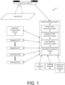
- FIG. 1 illustrates an example system 1 for performing worksite analysis.
- the system 1 may comprise a worksite analysis engine 10 and an autonomous vehicle 20. Additionally, the system 1 may comprise an equipment transportation vehicle 40, equipment 50 and 51, and crew devices 60 and 61. Further, the system 1 may also comprise a GIS (geographic information system) database 70, a topology database 80, and an equipment attribute database 90.
- GIS geo information system
- the worksite analysis engine 10 may be configured to gather information from a number of sources to perform various functionalities as described herein.
- the worksite analysis engine 10 may comprise a number of sub-engines, according to some example embodiments, that may be stand-alone engines that need not be bundled into the worksite analysis engine 10 as shown in FIG. 1 .
- the worksite analysis engine 10 may comprise a virtual layout generation engine 12, an equipment path generation engine 14, a crew workflow generation engine 16, and a workflow compliance engine 18. These engines may be configured to perform various functionalities as further described below by employing configured processing circuitry of the worksite analysis engine 10.
- the worksite analysis engine 10 may comprise processing circuitry 101, which may be configured to receive inputs and provide outputs in association with the various functionalities of, for example, the virtual layout generation engine 12, the equipment path generation engine 14, the crew workflow generation engine 16, and the workflow compliance engine 18.
- the worksite analysis engine 10 comprises the processing circuitry 101 comprising a memory 102, a processor 103, a user interface 104, and a communications interface 105.
- the processing circuitry 101 may be operably coupled to other components of the worksite analysis engine 10 that are not shown in FIG. 2A .
- the processing circuitry 101 may be configured to perform the functionalities of the worksite analysis engine 10, and more particularly the virtual layout generation engine 12, the equipment path generation engine 14, the crew workflow generation engine 16, and the workflow compliance engine 18, as further described herein.
- processing circuitry 101 may be in operative communication with or embody, the memory 102, the processor 103, the user interface 104, and the communications interface 105. Through configuration and operation of the memory 102, the processor 103, the user interface 104, and the communications interface 105, the processing circuitry 101 may be configurable to perform various operations as described herein. In this regard, the processing circuitry 101 may be configured to perform computational processing, memory management, user interface control and monitoring, and manage remote communications, according to an example embodiment. In some embodiments, the processing circuitry 101 may be embodied as a chip or chip set.
- the processing circuitry 101 may comprise one or more physical packages (e.g., chips) including materials, components or wires on a structural assembly (e.g., a baseboard).
- the processing circuitry 101 may be configured to receive inputs (e.g., via peripheral components), perform actions based on the inputs, and generate outputs (e.g., for provision to peripheral components).
- the processing circuitry 101 may include one or more instances of a processor 103, associated circuitry, and memory 102.
- the processing circuitry 101 may be embodied as a circuit chip (e.g., an integrated circuit chip, such as a field programmable gate array (FPGA)) configured (e.g., with hardware, software or a combination of hardware and software) to perform operations described herein.
- a circuit chip e.g., an integrated circuit chip, such as a field programmable gate array (FPGA)
- FPGA field programmable gate array
- the memory 102 may include one or more non-transitory memory devices such as, for example, volatile or non-volatile memory that may be either fixed or removable.
- the memory 102 may be configured to store information, data, applications, instructions or the like for enabling, for example, the functionalities described with respect to the virtual layout generation engine 12, the equipment path generation engine 14, the crew workflow generation engine 16, and the workflow compliance engine 18.
- the memory 102 may operate to buffer instructions and data during operation of the processing circuitry 101 to support higher-level functionalities, and may also be configured to store instructions for execution by the processing circuitry 101.
- the memory 102 may also store image data, equipment data, crew data, and virtual layouts as described herein. According to some example embodiments, such data may be generated based on other data and stored or the data may be retrieved via the communications interface 105 and stored.
- the processing circuitry 101 may be embodied in a number of different ways.
- the processing circuitry 101 may be embodied as various processing means such as one or more processors 103 that may be in the form of a microprocessor or other processing element, a coprocessor, a controller or various other computing or processing devices including integrated circuits such as, for example, an ASIC (application specific integrated circuit), an FPGA, or the like.
- the processing circuitry 101 may be configured to execute instructions stored in the memory 102 or otherwise accessible to the processing circuitry 101.
- the processing circuitry 101 may represent an entity (e.g., physically embodied in circuitry - in the form of processing circuitry 101) capable of performing operations according to example embodiments while configured accordingly.
- the processing circuitry 101 when the processing circuitry 101 is embodied as an ASIC, FPGA, or the like, the processing circuitry 101 may be specifically configured hardware for conducting the operations described herein.
- the processing circuitry 101 when the processing circuitry 101 is embodied as an executor of software instructions, the instructions may specifically configure the processing circuitry 101 to perform the operations described herein.
- the communication interface 105 may include one or more interface mechanisms for enabling communication with other devices external to worksite analysis engine 10, via, for example, a network, which may, for example, be a local area network, the Internet, or the like, through a direct (wired or wireless) communication link to another external device, or the like.
- the communication interface 105 may be any means such as a device or circuitry embodied in either hardware, or a combination of hardware and software, that is configured to receive or transmit data from/to devices in communication with the processing circuitry 101.
- the communications interface may comprise, for example, a radio frequency identification tag reader capable of reading tags in close proximity to the communications interface to gather information from the tag (e.g., identification data) and to determine a proximity of the tag to the communications interface.
- the communications interface 105 may be a wired or wireless interface and may support various communications protocols (WIFI, Bluetooth, cellular, or the like).
- the communications interface 105 of the worksite analysis engine 10 may be configured to communicate directly or indirectly to various components of the system 1 of FIG. 1 .
- the worksite analysis engine 10 may be configured to communicate directly or indirectly with the autonomous vehicle 20, the equipment transportation vehicle 40, the equipment 50 and 51, the crew device 60 and 61, the GIS database 70, the topology database 80, and/or the equipment database 90.
- the user interface 104 may be controlled by the processing circuitry 101 to interact with peripheral devices that can receive inputs from a user or provide outputs to a user.
- the user interface 104 may be configured to provide the inputs (e.g., from a user) to the processor 103, and the processor 103 may be configured to receive the inputs from the user interface 104 and act upon the inputs to, for example, determine and output a result via the user interface 104.
- a user may interact with the user interface 104 to input a stripping pattern for mowing an area of the worksite 30 and indications of the stripping pattern may be provided to the processor 103 for analysis and determination of a path as further described herein.
- the camera 126 may be configured to capture images of a selected area around the autonomous vehicle 20.
- the camera 126 may be a digital imaging device configured to receive light to capture an image and convert the light into data representative of the light captured by the camera 126 as a component of image data as described herein.
- the camera 126 may be controlled by the processing circuitry 120 to capture images as requested by the processing circuitry 120.
- the processing circuitry 120 may be configured to cause images to be captured such that the images may be combined (e.g., overlapping images) to generate a larger image or model from the component captured images.
- the camera 126 may be stationary or moveable relative to the autonomous vehicle 20 to which the camera 126 is affixed. In example embodiments wherein the camera is stationary, the autonomous vehicle 20 may move into different physical positions to capture a desired image. Alternatively, if the camera 126 is moveable, the processing circuitry 120 may be configured to aim the camera 126 at a target area to capture an image using a motorized pivot or turret.
- an angle of perspective (e.g., relative to the ground) may be stored in association with a captured image.
- the camera 126 may be configured to capture images at different perspectives (i.e., not simply overhead images aimed straight down). Such perspective images may be combined and leveraged to generate geospatial models that include topological data indicating terrain slopes and the like.
- the position sensor 127 may be circuitry configured to determine a current position of the autonomous vehicle 20 and may generate position data indicative of the position of the autonomous vehicle 20.
- the position of the autonomous vehicle 20 may be defined with respect to a coordinate system (e.g., latitude and longitude). Further, the position sensor 127 may be configured to determine an orientation of the autonomous vehicle 20 with respect to, for example, parameters such as pitch, roll, and yaw.
- the position and orientation of the autonomous vehicle 20 as determined by the position sensor 127 may be components of position data for the autonomous vehicle 20.
- the position sensor 127 may, for example, include circuitry (including, for example, antennas) configured to capture wireless signals that may be used for determining a position of the position sensor 127 and the autonomous vehicle 20 based on the signals.
- the position sensor 127 may be configured to receive global positioning system (GPS) signals to determine a position of the autonomous vehicle 20.
- GPS global positioning system
- RTK real-time kinematic
- the receipt of wireless signals may also be leveraged to determine a position based on locating approaches such as received signal strength indication (RSSI), time-difference-of-arrival (TDOA), and the like.
- RSSI received signal strength indication
- TDOA time-difference-of-arrival
- the position sensor 127 may be configured to determine a position of the autonomous vehicle 20 using locating techniques such as received signal strength, time of arrival, or the like.
- the autonomous vehicle 20 may include one or more sensors 129 which may take a variety of different forms.
- the sensor 129 may be configured to take one or more measurements of the worksite 30 under the control of the processing circuitry 120.
- the measurement information may be coupled with position data to indicate a position or location within the worksite 30 where the measurement was taken.
- the measurement information gathered by the sensor(s) 129 may be provided to the worksite analysis engine 10 (e.g., possibly coupled with the respective position data) in the form of sensor data and integrated with the image data to be used as input component for the determinations made by the worksite analysis engine 10 or the sub-engines thereof.
- the sensor 129 may be configured to gather additional information to assist with topographical mapping.
- the sensor 129 may be configured to use RADAR (radio azimuth direction and ranging), LiDAR (light detection and ranging), or the like to make measurements and capture information regarding, for example, changes in elevation and contours of the surface of the worksite 30 to be provided to the worksite analysis engine 10.
- RADAR radio azimuth direction and ranging
- LiDAR light detection and ranging
- the sensor 129 may additionally or alternatively be configured to measure characteristics of the soil in the worksite 30 to be provided as sensor data.
- the sensor 129 may be a type of imaging sensor that detects, for example, temperature variations (e.g., via infrared light) across the worksite 30.
- the sensor 129 may detect a hydration level in the soil at the worksite 30.
- hydration levels may be detected via imaging techniques at certain electromagnetic wavelengths.
- the senor 129 may include a probe that may penetrate the surface of the worksite 30 (e.g., extend a desired depth into the soil) to take hydration measurements (e.g., at selected locations across the worksite 30). Additionally or alternatively, such a sensor 129 may be configured to take other measurements of the soil, such as, for example, pH, color, compaction, organic content, texture, or the like.
- the equipment transportation vehicle 40 may be a truck, van, trailer, or the like that is configured to transport equipment to a worksite.
- the equipment transportation vehicle 40 may comprise processing circuitry 140, which may include memory 142, processor 143, user interface 144, and communications interface 145.
- the processing circuitry 140 including the memory 142, the processor 143, the user interface 144, and the communications interface 145, may be structured the same or similar to the processing circuitry 101 with the memory 102, the processor 103, the user interface 104, and the communications interface 105, respectively.
- the processing circuitry 140 may be configured to perform or control the functionalities of the equipment transportation vehicle 40 as described herein.
- the user interface 124 of the processing circuitry 120 may be configured to establish a communications link with the worksite analysis engine 10 to provide the worksite analysis engine 10 with data, such as, position data for the equipment transportation vehicle 40.
- the equipment transportation vehicle 40 may also comprise a position sensor 146 and a propulsion and navigation unit 147.
- the processing circuitry 120 may be configured to control the operation of the position sensor 146 and the propulsion and navigation unit 127.
- the position sensor 146 may be structured and configured in the same or similar manner as the position sensor 127.
- the equipment transportation vehicle 40 may include a propulsion and navigation unit 147.
- the propulsion and navigation unit 147 may include the mechanisms and components configured to move the equipment transportation vehicle 40.
- the propulsion and navigation unit 147 may comprise motorized wheels, tracks, or the like configured to assist with moving the equipment transportation vehicle 40.
- the propulsion and navigation unit 128 may include a user interface for driving the equipment transportation vehicle 40 by a crew member.
- the equipment 50 may be a tool or device that has utility in the context of the worksite 30.
- the equipment 50 may be vegetation maintenance equipment. In this regard, if vegetation maintenance is to be performed at the worksite 30, the equipment 50 may be a ride-on or push mower, a trimmer, a blower, an aerator, a fertilizer spreader, a pruner, or the like.
- the equipment 50 may comprise processing circuitry 150, which may include memory 152, processor 153, user interface 154, and communications interface 155.
- the processing circuitry 150 including the memory 152, the processor 153, the user interface 154, and the communications interface 155, may be structured the same or similar to the processing circuitry 101 with the memory 102, the processor 103, the user interface 104, and the communications interface 105, respectively.
- the processing circuitry 150 may be configured to perform or control the functionalities of the equipment 50 as described herein.
- the communications interface 155 of the processing circuitry 150 may be configured to establish a communications link with the worksite analysis engine 10 to provide the worksite analysis engine 10 with data, such as, position data for the equipment 50.
- the operation sensor 157 may be a single sensor or a plurality of sensors that monitor and log data regarding the operation of the equipment 50.
- the operation sensor 157 may be configured to monitor and log rotation per minute (RPM) data, fuel quantity and utilization data, gear usage data (e.g., high gear, low gear, reverse), idle time data, and the like.
- RPM rotation per minute
- fuel quantity and utilization data fuel quantity and utilization data
- gear usage data e.g., high gear, low gear, reverse
- idle time data e.g., high gear, low gear, reverse
- equipment operation data may be communicated to the worksite analysis engine 10 for use in compliance analyses by the workflow compliance engine 18.
- the equipment 50 may include a propulsion and navigation unit 158.
- the propulsion and navigation unit 158 may include the mechanisms and components configured to move the equipment 50.
- the propulsion and navigation unit 158 may comprise motorized wheels, tracks, or the like configured to assist with moving the equipment 50.
- the propulsion and navigation unit 158 may operably couple with the user interface 154 for driving the equipment transportation vehicle 40 by a crew member.
- the equipment 50 may include a display 151, which may be, for example, an LCD display.
- information may be provided to a crew member operating the equipment 50 via the display 151. Such information may be rendered by the processing circuitry 150 on the display 151 in the form of, for example, a determined equipment path for the operator/crew member to follow when using the equipment 50 at the worksite 30.
- the equipment 50 may also include a working unit 159.
- the working unit 159 may be the component or components of the equipment 50 that perform a work action (e.g., cutting, blowing, aerating, spraying, or the like).
- a work action e.g., cutting, blowing, aerating, spraying, or the like.
- the working unit 159 may comprise cutting blades and a deck for mowing turf and the associated control and power systems.
- the working unit 159 may comprise a fan, an air-directing nozzle, and the associated control and power systems to support operation of the fan.
- crew device 60 may be the same or similar to crew device 60.
- the crew device 60 may be a device that worn or carried by a crew member and is configured to track a position of the crew member. Additionally, according to some example embodiments, the crew device 60 may be configured to communicate with or read a tag on a piece of equipment (e.g., equipment 50) to determine a proximity of the equipment and determine that the crew member is operating the equipment. As such, the crew device 60 may clip to a crew member's belt, be affixed to a lanyard, or the like.
- the autonomous vehicle 20 may be configured to capture images of the same space from different perspective angles. By capturing the images in this manner three-dimensional information may be extracted from the collection of images to determine the size, shape, and placement of objects, other items of interest, and the spatial geography of the items of interest by the virtual layout generation engine 12. Further, topology data may be determined indicating slopes within the landscape of the worksite 30 based on the perspective angles of the captured images.
- the autonomous vehicle 20 may navigate the worksite 30 to collect image data comprising images of the worksite 30 with corresponding position coordinates (e.g., a form of position data) for the images.
- the position coordinates may include orientation coordinates indicating pitch, roll, and yaw, as well as altitude, to be able to define a perspective and perspective angles for the images captured.
- the autonomous vehicle 20 may also collect sensor data (e.g., captured by sensor(s) 129).
- the image data and/or the sensor data may be provided by the autonomous vehicle 20 for receipt by the worksite analysis engine 10.
- the autonomous vehicle 20 may be configured to wirelessly transmit the image data and/or the sensor data via a network to the worksite analysis engine 10 or, according to some example embodiments, the autonomous vehicle 20 may be configured to store the image data and/or sensor data on, for example, a removable memory (e.g., memory 122 or a component thereof) that may be delivered to the worksite analysis engine 10 for upload.
- a removable memory e.g., memory 122 or a component thereof
- the worksite analysis engine 10 may be configured to generate a virtual layout of the worksite 30 based on various data (e.g., image data and sensor data) and generate workflows to optimize maintenance work at the worksite 30 based on the virtual layout, possibly in combination with other data retrieved by the worksite analysis engine 10.
- the worksite analysis engine 10 may be configured to generate the virtual layout via the processing circuitry 101.
- the virtual layout generation engine 12 may be configured to receive data and generate the virtual layout of the worksite 30 based on the received data.
- the received data may include image data and/or sensor data captured by the autonomous vehicle 20. Additionally or alternatively, the received data may include geographic data received from the GIS database 70.
- the GIS database 70 may be, for example, a government maintained database of property records indicating surveyed meets and bounds of property plots and associated satellite imagery. Additionally or alternatively, the GIS database 70 may be a commercial database (e.g., a real estate business database) that includes property boundary lines and satellite imagery.
- the GIS database 70 may include satellite imagery that may be received by the virtual layout generation engine 12 for use in developing the virtual layout.
- the virtual layout generation engine 12 may also receive data from a topology database 80. Again, the topology database 80 may be a government or commercial database indicated property elevations and topographic contours. The topology database 80 may include data provided as satellite topography.
- the virtual layout generation engine 12 may be configured to generate a virtual layout in the form of a geospatial model of the worksite 30 based on one or more of the image data, sensor data, data from the GIS database 70, or data from the topology database 80.
- the virtual layout generation engine 12 may be configured to match edges of the captured images using the content of the images and the corresponding position data to generate the virtual layout in the form of a three-dimensional geospatial model.
- the virtual layout generation engine 12 may include functionality to identify and classify areas and objects within the virtual layout. To do so, the virtual layout generation engine 12 may evaluate colors, textures, and color and texture transitions within, for example, the image data to identify objects and area boundaries against a comparison object database.
- the virtual layout generation engine 12 may be configured to identify and classify lawn or turf areas and define boundaries for the lawn or turf areas. Further, the virtual layout generation engine 12 may be configured to identify and classify planting beds and define boundaries for the planting beds. Further, the virtual layout generation engine 12 may be configured to identify and classify structures (e.g., houses, buildings, fences, decks, etc.) and define boundaries for the structures. Additionally, the virtual layout generation engine 12 may be configured to identify and classify pavement areas (e.g., roads, driveways, sidewalks, etc.) and define boundaries for the pavement areas.
- structures e.g., houses, buildings, fences, decks, etc.
- pavement areas e.g., roads, driveways, sidewalks, etc.
- the virtual layout generation engine 12 may also be configured receive vegetation data and analyze coloration and shapes of, for example, leaves and other vegetation characteristics to identify and classify the types of vegetation (e.g., trees, bushes, turf, annuals, etc.) on the worksite 30 based on the received vegetation data and indicate the placement of the vegetation within virtual layout.
- vegetation data e.g., trees, bushes, turf, annuals, etc.
- the virtual layout generation engine 12 may also consider human survey information that may be provided to the virtual layout generation engine 12 relating to the worksite 30.
- the human survey information may indicate spatial information such as the placement of planting beds, structures, pavement areas, and the like.
- the human survey information may also indicate vegetation types and locations within the worksite 30.
- the human survey information may be entered into a separate terminal or directly into the worksite analysis engine 10 to be received via the communications interface 105 or the user interface 104, respectively.
- the virtual layout may be formed as a geospatial model comprising the topography of the worksite 30 that can be analyzed to assist with equipment path determinations and workflow generation as further described herein.
- the virtual layout may be used to determine distances between the identified and classified objects.
- the virtual layout may provide a digital representation of the physical worksite 30 at the time that the images used to generate the virtual layout were captured.
- the virtual layout may also be generated based on historical virtual layouts for the worksite 30.
- a virtual layout may include a temporal element and the virtual layout may describe the state of the worksite 30 over time.
- snapshot or time captured virtual layouts may be combined to identify changes that have occurred at the worksite 30.
- a virtual layout that incorporates historical information may indicate vegetation growth (e.g., tree growth or turf growth).
- vegetation growth e.g., tree growth or turf growth
- such a virtual layout may show differences in the landscape of the worksite 30 due to, for example, erosion or degradation of ground cover (e.g., degradation of mulch).
- the virtual layout may also show differences due to the presence of movable objects such as debris or toys that may be moveable prior to performing worksite maintenance.
- the worksite analysis engine 10 may also include an equipment path generation engine 14.
- the equipment path generation engine 14 may be configured to analyze the virtual layout in combination with other data to determine an efficient and effective equipment path for performing a worksite maintenance task. Data in addition to the virtual layout that may be evaluated and incorporated when determining an equipment path. Such data may include equipment data and crew data.
- the equipment path may be defined as a direction or pattern of movement for equipment use in an area. However, in some example embodiments, the equipment path may indicate a specific route indicating exact positions for the equipment as the equipment is utilized to complete a task.
- the equipment data that may be used to generate an equipment path may include a list of equipment available to be deployed at the worksite 30. Such a list may be an inventory list of the equipment that is present on the equipment transportation vehicle 40.
- the equipment data may also include equipment attributes for the equipment on the inventory list. Such attributes may indicate, for example, for a ride-on mower, turning radius, deck width, deck height, maximum slope, speed, clipping catch capacity, and the like.
- the crew data may indicate a number of available crew members that may be utilized at the worksite 30. Crew data may also indicate certain qualifications or experience of the individual crew member. For example, the crew data may indicate equipment that a crew member is qualified to use or that the crew member has proven to have a relatively high effectiveness using. Further, the crew data may indicate a classification or rank of a crew member as, for example, a supervisor, a senior crew member, a junior crew member, or the like.
- an equipment path may be generated by the equipment path generation engine 14, via the processing circuitry 101, as an efficient and effective path for implementing selected equipment within the worksite 30.
- the equipment path generation engine 14 may be configured to generate the equipment path based on the virtual layout, where the virtual layout includes topographic information for analysis in determining the equipment path.
- the equipment path may also be based on desired path parameters, such as, for example, a desired striping pattern (e.g., a user-defined striping pattern) for the turf, a desired hedge height or the like.
- the equipment path may be generated based on recent weather data.
- Such weather data may comprise precipitation data and sun exposure data.
- the weather data may, for example, indicate that there has been little precipitation and high sun exposure, and therefore only the shaded areas within the worksite 30 may require mowing and the equipment path may be generated accordingly.
- the weather data may indicate that substantial precipitation and low sun exposure has occurred recently and therefore low areas of the worksite 30 may be removed from the equipment path for a ride-on mower to prevent ruts in the turf.
- the equipment path generation engine 14 may be configured to generate the equipment path based on the virtual layout and work zones defined within the worksite 30, as further described below. In this regard, for example, the equipment path may be generated for work within a particular work zone, and thus, the equipment path may be, in some instances, limited to routing the crew member and the associated equipment within the work zone.
- the equipment path may indicate the path that the mower should move from the equipment transportation vehicle 40 to the worksite 30, through the worksite 30 to perform mowing, and return to the equipment transportation vehicle 40.
- the equipment path may be determined based on the equipment data to determine areas from the virtual layout where, for example, a ride-on mower may not have access because of sloped terrain, a small gate, an area being smaller than the deck width, turning radius limitations, or the like.
- the equipment path generation engine 14 may indicate a path that a crew member may move from the equipment transportation vehicle 40 to each area that needs to be trimmed and return to the equipment transportation vehicle 40.
- some equipment paths may be dependent upon other equipment paths or the capabilities of other equipment.
- the equipment path for the trimmer may be dependent upon the accessibility of the ride-on mower to all areas of the worksite 30, and there may be areas that are not accessible to the ride-on mower, and therefore the equipment path for the trimmer may include some or all of those areas that are not accessible to the ride-on mower.
- the equipment path may also be based on a requirement to return to a location during completion of a task.
- the equipment path may be defined to return to the equipment transportation vehicle 40 to empty the clipping catch at an efficient point in the equipment path based on, for example, the clipping catch capacity of the equipment.
- the equipment path may be provided (e.g., transmitted or otherwise delivered) to, for example, the equipment 50.
- the equipment 50 may be configured to store the equipment path in the memory (e.g., memory 142) of the equipment 50.
- the crew member may retrieve the equipment path for output via the user interface 144, or, more specifically, via a display of the user interface 144.
- the equipment path may be output to the crew member to enable the crew member to follow the determined equipment path during execution of the task.
- the worksite analysis engine 10 may also be configured to implement a crew workflow generation engine 16.
- the crew workflow generation engine 16 may be configured to generate a workflow for the crew members servicing the worksite 30.
- the workflow may comprise a list (e.g., a sequenced list) of workflow assignments to be performed by a crew member when servicing the worksite 30.
- a workflow assignment may comprise a task, equipment to perform the task, and an equipment path (as described above) for performing the task.
- a workflow assignment may include a task of mowing, equipment for the task may be a ride-on mower, and the equipment path may be defined as provided by the equipment path generation engine 14.
- a workflow assignment may also indicate a work zone for the task.
- the crew workflow generation engine 16 may be configured to analyze the virtual layout to determine work zones within the worksite 30.
- the crew workflow generation engine 16 may be configured to determine sub-boundaries within the worksite 30 where, for example, topology changes (e.g., areas with increased or decreased slope), access changes (e.g., a fenced in area), pavement boundaries, worksite boundaries, or the like.
- Work zones may also be defined based on the equipment needed to service, for example, the vegetation within the work zone. For example, a work zone may be defined by an area that has a steep grade because a ride-on mower may not be able to mow the area and a push mower may be needed to mow that area.
- a work zone may be defined in association with a densely treed area where only a trimmer can be used to maintain grasses that may grow in such an area.
- the crew workflow generation engine 16 may therefore define the work zones as piece-wise geographic regions within the worksite 30. As such, for example, boundaries of the work zones may be determined based on physical changes indicated in the virtual layout (e.g., a change from turf to pavement), a need for a different piece of equipment to maintain the area, or the like.
- the workflow may be a maintenance execution plan for each member to complete, for example, in unison upon beginning the maintenance effort at a worksite 30.
- the workflow and the workflow assignments therein may be determined based on the virtual layout, the equipment data, and the crew data. Additionally, the workflow and the workflow assignments therein may, according to some example embodiments, be based on the defined work zones for the worksite 30. Additionally, the workflow and the workflow assignments therein may also be based on the weather data (e.g., including precipitation data, sun exposure data, or the like) as described above, or sensor data.
- the workflow and the workflow assignment therein may be defined based on safety criteria such that crew members may be located, for example, in different work zones at the same time to reduce interaction that increases the likelihood of a safety incident.
- the equipment selected for a task within the workflow may be determined based on the type of task and the type of, for example, vegetation being maintained.
- a mower provided on the equipment list of the equipment data may be selected for use when maintaining turf.
- the crew workflow generation engine 16 may be configured to recommend purchase of a new piece of equipment, based on the equipment data and the virtual layout, that could more efficiently complete the task.
- Such information regarding equipment that is not in the equipment list may be retrieved, for example, from other sources of information such as websites and databases of equipment information provided by equipment sellers.
- the crew workflow generation engine 16 may be configured to determine an efficiency payback associated with the purchase of the new equipment that indicates when use of the new equipment at the worksite 30 (and elsewhere) may increase profits due to the efficiency increase resulting in payback in the amount of the purchase price over a determined period of time.
- the crew workflow generation engine 16 may also analyze the virtual layout to determine an efficient location to park the equipment transportation vehicle 40.
- the determination of the location of the equipment transportation vehicle 40 may also be a factor when generating equipment paths as described above.
- the determined location of the equipment transportation vehicle 40 may be a location that minimizes travel distances of equipment to the worksite 30.
- the workflow assignment and tasks of the workflow may also be factors evaluated by the crew workflow generation engine 16 when determining a location for the equipment transportation vehicle 40 and for the generation of equipment paths.
- the worksite analysis engine 10 may also include a workflow compliance engine 18.
- the workflow compliance engine 18 may be configured to evaluate actual execution of the workflow by the crew to determine compliance with the workflow.
- a workflow compliance score may be calculated based on the crew's execution of the workflow.
- Workflow compliance may be performed based on tracked data (e.g., equipment operation data and equipment position data) regarding the utilization and location of the equipment by the crew with respect to the workflow.
- tracked data e.g., equipment operation data and equipment position data
- the workflow compliance engine 18 may receive position data from the equipment position sensor 156 and the crew device position sensor 166. Additionally, the workflow compliance engine 18 may collect data regarding operation of the equipment from data captured by the operation sensor 157 of the equipment 50.
- workflow compliance analyses may be performed, for example, with respect to the determined equipment path indicated in the workflow.
- equipment position data captured by the equipment 50 may be compared to the generated equipment path to determined differences between the actual path taken and the proposed equipment path. Such differences may be a factor in a compliance score.
- compliance analysis may also be performed with respect to the type of equipment being used for a task within the workflow. For example, the workflow may indicate that a push mower is to be used for mowing a particular work zone, but the operation data and the position data of the ride-on mower may indicate that the push mower was not used and the ride-on mower was used, which would be out of compliance with the workflow.
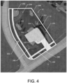
- FIG. 3 an overhead view of a worksite 30 is shown.
- Image data of the worksite 30 may be captured by the autonomous vehicle 20 as indicated by image captures 200 across the entirety of the worksite 30.
- FIG. 3 shows images captured in a two dimensional plane above the worksite 30, it is understood that the autonomous vehicle 20 may be configured to capture image data at a number of different perspectives to facilitate generation of a virtual layout of the worksite 30 in three dimensions as a geospatial model that includes topographic information.
- the worksite 30 is shown as an example virtual layout that may be generated by the virtual layout generation engine 12.
- a worksite boundary 32 may be generated to define the extents of the worksite 30, for example, based on GIS data or the like as described herein.
- the virtual layout includes areas identified and classified as planting beds 202, which may include plants, shrubs, trees, or the like.
- the virtual layout includes an area identified and classified as a structure 204 in the form of the house.
- the virtual layout includes an area identified and classified as pavement 206 which includes the areas of the driveway and the sidewalk.
- the virtual layout also includes contour lines 208 indicating sloped areas of the worksite 30 that have been determined based on topographic data.
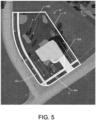
- equipment path generation engine 14 has analyzed the virtual layout with equipment data and determined equipment paths.
- the equipment paths may be determined for different areas of the worksite 30 based on, for example, the type of equipment to be used and the topography of the area.
- the equipment paths 300, 302, 304, and 306 are defined.
- the equipment paths 300, 302, 304, and 306 may be defined directions or patterns of movement for use by a crew member operating, fro example, a ride-on mower in accordance with the equipment paths 300, 302, 304, and 306.
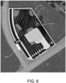
- FIG. 6 illustrates a more specifically defined equipment path 400.
- the equipment path 400 may also be for a ride-on mower, but the equipment path 400 indicates the exact location for movement of the ride-on mower throughout the mowing task. Additionally, the location of an equipment transportation vehicle 410 is shown. In this regard, the crew workflow generation engine 16 may have analyzed the virtual layout and determined an efficient location for parking the equipment transportation vehicle 410 for beginning and ending the equipment path for the task of mowing using a ride-on mower, as well as other tasks in the workflow.
- the worksite 30 may be divided by the crew workflow generation engine 16 into a plurality of work zones.
- the work zones 500, 502, 504, and 506 have been defined, in addition to a work zone associated with the paved area 206.
- the work zones have been defined with boundaries based on the boundaries of the worksite 30 and pavement boundaries in some instances.
- the boundaries between work zone 502 and 500, and work zone 504 and 500 may be based on, for example, the presence of a structure in the form of a fence.
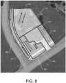
- equipment paths may be defined within the context of the work zones individually, as shown in FIG. 8 .
- equipment paths 501, 505, and 507 may be defined within each of the work zones 500, 504, and 506, respectively, as directions or patterns of movement, for example, for a ride-on mower completing the task of mowing within each of the work zones 500, 502, and 504.
- a push mower is designated as the equipment for completing the task of mowing in the work zone 502 in accordance with the equipment path 503.
- an example workflow may be generated by the crew workflow generation engine 16 as provided in Table 1 below.
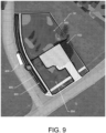
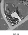
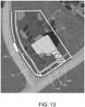
- the example workflow of Table 1 includes work assignments described with respect to FIGs. 9 through 13 .
- the crew workflow generation engine 16 has generated a workflow for the worksite 30 using two crew members (i.e., crew member 1 and crew member 2).
- the work assignments in the same row are scheduled to be performed at the same time and are planned to require a similar amount of time to complete.
- each workflow assignment within the workflow may be defined by a task, equipment, work zone, and equipment path.
- the equipment path 600 for workflow assignment 1a is shown. Additionally, in FIG. 9 , the crew workflow generation engine 16 has also determined an efficient location of for parking the equipment transportation vehicle 400, as shown.
- crew member 1 is assigned to a task of mowing with a clipping catch using the equipment being a ride-on mower in work zone 506 using equipment path 600.
- the equipment path 600 begins and ends at the equipment transportation vehicle 400 to provide for emptying the clipping catch at the equipment transportation vehicle 400.
- crew member 2 is assigned workflow assignment 1b (to be performed at the same time as workflow assignment 1a) of trimming, using the trimmer, in work zone 502.
- crew member 1 and crew member 2 are not assigned to work in the same work zone at the same time for safety purposes.
- the equipment path generation engine 14 may have generated an equipment path for trimming, in this example workflow the equipment path for the trimming tasks are not shown.
- crew member 1 is assigned to workflow assignment 2a, which is to mow with a clipping catch using the ride-on mower in work zone 500 using equipment path 602.
- the equipment path 602 again begins and ends at the equipment transportation vehicle 400 to provide for emptying the clipping catch at the equipment transportation vehicle 400.
- crew member 2 is assigned workflow assignment 2b (to be performed at the same time as workflow assignment 2a) of trimming, using the trimmer, in work zone 504.
- crew member 1 is assigned to workflow assignment 3a, which is to mow with a clipping catch using the ride-on mower in work zone 504 using equipment path 604.
- the equipment path 604 again begins and ends at the equipment transportation vehicle 400 to provide for emptying the clipping catch at the equipment transportation vehicle 400.
- crew member 2 is assigned workflow assignment 3b (to be performed at the same time as workflow assignment 3a) of trimming, using the trimmer, in work zone 506.
- crew member 1 is assigned to workflow assignment 4a, which is to mow with a clipping catch using the push mower in work zone 502 using equipment path 606.
- the equipment path 606 again begins and ends at the equipment transportation vehicle 400 to provide for emptying the clipping catch at the equipment transportation vehicle 400.
- crew member 2 is assigned workflow assignment 4b (to be performed at the same time as workflow assignment 4a) of trimming, using the trimmer, in work zone 500.
- crew member 1 is assigned to workflow assignment 5a, which is to blow using the blower in the pavement work zone defined at 206 using equipment path 608.
- the equipment path 608 again begins and ends at the equipment transportation vehicle 400 to provide for removing and returning the blower to the equipment transportation vehicle 400.
- crew member 2 is assigned workflow assignment 5b (to be performed at the same time as workflow assignment 5a) of pruning, using the pruners, in work zone 500.
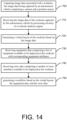
- the example method may include, at 700, capturing image data associated with a worksite, where the image data is captured by an autonomous vehicle (e.g., autonomous vehicle 20) comprising a camera and a position sensor.
- the autonomous vehicle may be configured to operate the camera and position sensor to capture the image data with corresponding position coordinates.
- sensor data may also be measured and otherwise captured by the autonomous vehicle.
- the example method may further include, at 710, receiving the image data (and in some cases sensor data) of the worksite captured by the autonomous vehicle by processing circuitry (e.g., processing circuitry 101) of a worksite analysis engine.
- the example method may include generating a virtual layout of the worksite based on the image data (and in some cases sensor data), by the processing circuitry.
- the example method may also include, at 730, receiving equipment data comprising a list of equipment available to be deployed at the worksite with corresponding equipment attributes, and at 740, receiving crew data comprising a number of crew members available to be deployed at the worksite.
- the example method may include generating a workflow based on the virtual layout, the equipment data, and the crew data.
- the workflow may comprise workflow assignments for each crew member at the worksite, and each workflow assignment may indicate a task, equipment to perform the task, and an equipment path for the task.
- the image data may include perspective angles corresponding to the images captured, and the example method may further comprise generating the virtual layout as a geospatial model of the worksite including topographic data based on the image data comprising the perspective angles. Additionally, the example method may comprise generating the equipment path based on the virtual layout comprising the topographic data.
- the example method may, additionally or alternatively comprise determining a plurality of work zones within the worksite based on the virtual layout, the equipment data, and the crew data, and generating the workflow based on the work zones.
- each workflow assignment may also indicate a work zone for a task.
- the example method may further comprise generating the equipment path based on the plurality of work zones.
- the equipment attributes for the equipment data may include information indicating a deck width and a turn radius.
- the example method may comprise generating the virtual layout based on vegetation data indicating types of vegetation within the worksite.
- the example method may further comprise generating the workflow based on weather data comprising precipitation data and sun exposure data, or sensor data. Additionally or alternatively, the example method may further comprise generating the virtual layout based on historical image data. In this regard, the example method may further comprise identifying moveable objects within the virtual layout based on differences between the historical image data and the image data captured by the autonomous vehicle.
Landscapes
- Business, Economics & Management (AREA)
- Engineering & Computer Science (AREA)
- Human Resources & Organizations (AREA)
- Strategic Management (AREA)
- Economics (AREA)
- Physics & Mathematics (AREA)
- General Physics & Mathematics (AREA)
- Entrepreneurship & Innovation (AREA)
- Theoretical Computer Science (AREA)
- Marketing (AREA)
- General Business, Economics & Management (AREA)
- Tourism & Hospitality (AREA)
- Development Economics (AREA)
- Game Theory and Decision Science (AREA)
- Operations Research (AREA)
- Quality & Reliability (AREA)
- Educational Administration (AREA)
- Multimedia (AREA)
- Remote Sensing (AREA)
- Health & Medical Sciences (AREA)
- General Health & Medical Sciences (AREA)
- Life Sciences & Earth Sciences (AREA)
- Aviation & Aerospace Engineering (AREA)
- Computer Vision & Pattern Recognition (AREA)
- Automation & Control Theory (AREA)
- Radar, Positioning & Navigation (AREA)
- Electromagnetism (AREA)
- Agronomy & Crop Science (AREA)
- Environmental Sciences (AREA)
- Primary Health Care (AREA)
- Mining & Mineral Resources (AREA)
- Marine Sciences & Fisheries (AREA)
- Animal Husbandry (AREA)
- Traffic Control Systems (AREA)
- Accounting & Taxation (AREA)
- Finance (AREA)
- Control Of Position, Course, Altitude, Or Attitude Of Moving Bodies (AREA)
Claims (15)
- Un système comprenant:un véhicule autonome (20) comprenant une caméra (126) et un capteur de position (127), le véhicule autonome (20) étant configuré pour faire fonctionner la caméra (126) et le capteur de position (127) afin de capturer des données d'image associées à un chantier (30), les données d'image comprenant des images du chantier (30) avec des coordonnées de position correspondantes;
etle moteur d'analyse de chantier (10) comprenant un circuit de traitement (101), le circuit de traitement (101) étant configuré pour:recevoir les données d'image du chantier (30) capturées par le véhicule autonome (20);générer un plan virtuel du chantier (30) sur la base des données d'image;recevoir des données sur l'équipement comprenant une liste d'équipements disponibles pour être déployés sur le chantier (30) avec les attributs d'équipement correspondantsrecevoir des données sur l'équipage comprenant un nombre de membres de l'équipage disponibles pour être déployés sur le chantier (30) générer un flux de travail basé sur la disposition virtuelle, les données relatives à l'équipement et les données relatives à l'équipe, le flux de travail comprenant des affectations de flux de travail pour chaque membre de l'équipe sur le chantier (30), chaque affectation de flux de travail indiquant une tâche, un équipement pour effectuer la tâche et un chemin d'équipement pour la tâche; caractérisé en ce que le système comprend en outre: au moins un équipement (50, 51) comprenant un circuit de traitement (150) configuré pour établir un lien de communication avec un moteur d'analyse de chantier (10) du système pour fournir au moteur d'analyse de chantier (10) des données de position et des données d'opération pour l'équipement (50, 51); un dispositif d'équipage (60, 61) configuré pour suivre la position d'un membre de l'équipage et configuré pour communiquer avec ou lire une étiquette sur l'équipement (50, 51) afin de déterminer la proximité de l'équipement (50, 51) et de déterminer que le membre de l'équipage utilise l'équipement (50, 51) et comprenant un circuit de traitement (160) configuré pour établir un lien de communication avec le moteur d'analyse de chantier (10) afin de fournir au moteur d'analyse de chantier (10) des données sur la position du dispositif d'équipage (60, 61);et dans lequel le circuit de traitement (101) est en outre configuré pour:
évaluer l'exécution réelle du flux de travail par l'équipage sur la base des données de position et des données de fonctionnement saisies par au moins un équipement (50, 51) et au moins un dispositif de l'équipage (60, 61). - Le système de la revendication 1, dans lequel les données d'image comprennent des angles de perspective correspondant aux images dans lequel le circuit de traitement (101) est configuré pour générer la disposition virtuelle sous la forme d'un modèle géospatial du chantier (30) comprenant des données topographiques sur la base des données d'image comprenant les angles de perspective; et
le circuit de traitement (101) est configuré pour générer le chemin de l'équipement sur la base de la disposition virtuelle comprenant les données topographiques. - Le système de la revendication 1, dans lequel le circuit de traitement (101) est en outre configuré pour déterminer une pluralité de zones de travail (500,...,506) à l'intérieur du chantier (30) sur la base de la disposition virtuelle, des données relatives à l'équipement et des données relatives à l'équipage; et
dans lequel le circuit de traitement (101) est configuré pour générer le flux de travail sur la base des zones de travail (500,...,506), chaque affectation de flux de travail indiquant également une zone de travail (500,...,506) pour une tâche. - Le système de la revendication 3, dans lequel le circuit de traitement (101) est configuré pour générer le chemin de l'équipement sur la base de la pluralité de zones de travail (500,...,506)
- Le système de la revendication 1, dans lequel les attributs de l'équipement pour les données de l'équipement comprennent des informations indiquant une largeur de pont et un rayon de braquage.
- Le système de la revendication 1, dans lequel le véhicule autonome (20) comprend un capteur configuré pour générer des données de capteur à intégrer aux données d'image dans le moteur d'analyse de chantier (10).
- Le système de la revendication 1, dans lequel le circuit de traitement (101) est configuré pour générer le flux de travail sur la base de données météorologiques comprenant des données de précipitations et des données d'exposition au soleil.
- Le système de la revendication 1, dans lequel le circuit de traitement (101) est configuré pour générer la disposition virtuelle sur la base de données d'images historiques, et dans lequel le circuit de traitement (101) est configuré pour identifier les objets mobiles dans la disposition virtuelle sur la base des différences entre les données d'images historiques et les données d'images capturées par le véhicule autonome (20).
- Le système de la revendication 1, comprenant en outre un équipement de gestion de la végétation, l'équipement de gestion de la végétation comprenant un capteur de position de l'équipement (156) configuré pour capturer une position de l'équipement afin de générer des données de position de l'équipement; et
le circuit de traitement (101) est en outre configuré pour déterminer la conformité avec le flux de travail sur la base des données relatives à la position de l'équipement. - Le système de la revendication 9, dans lequel l'équipement de gestion de la végétation comprend en outre une interface utilisateur (154) configurée pour fournir le chemin de l'équipement à un membre de l'équipe.
- Le système de la revendication 1, dans lequel le circuit de traitement (101) est configuré pour générer la trajectoire de l'équipement sur la base de la disposition virtuelle comprenant un motif de bandes de gazon défini par l'utilisateur.
- Le système de la revendication 1, dans lequel le circuit de traitement (101) est en outre configuré pour déterminer un emplacement de stationnement pour un véhicule de transport d'équipement (40) sur la base de la disposition virtuelle et du flux de travail.
- Le système de la revendication 1, dans lequel le circuit de traitement (101) est en outre configuré pour générer une recommandation d'achat d'équipement sur la base de l'agencement virtuel et des données relatives à l'équipement.
- Une méthode mise en œuvre par ordinateur comprenant:capturer des données d'image associées à un chantier (30), les données d'image étant capturées par un véhicule autonome (20) comprenant une caméra (126) et un capteur de position (127), le véhicule autonome (20) étant configuré pour faire fonctionner la caméra (126) et le capteur de position (127) afin de capturer les données d'image avec des coordonnées de position correspondantes;recevoir les données d'image du chantier (30) capturées par le véhicule autonome (20) par le circuit de traitement (101) d'un moteur d'analyse de chantier (10);générer un plan virtuel du chantier (30) sur la base des données d'image par le circuit de traitement (101);recevoir des données sur l'équipement comprenant une liste d'équipements disponibles pour être déployés sur le chantier (30) avec les attributs d'équipement correspondants;générer un flux de travail basé sur la disposition virtuelle, les données relatives à l'équipement et les données relatives à l'équipe, le flux de travail comprenant des affectations de flux de travail pour chaque membre de l'équipe sur le chantier (30), chaque affectation de flux de travail indiquant une tâche, l'équipement (50, 51) pour effectuer la tâche et un chemin d'équipement pour la tâchecaractérisé parréception des données de position et des données de fonctionnement de l'équipement (50, 51) à partir du circuit de traitement (150) d'au moins un équipement (50, 51) configuré pour établir un lien de communication avec le moteur d'analyse de chantier (10)recevoir les données relatives à l'équipage comprenant le nombre de membres de l'équipage disponibles pour être déployés sur le chantier (30); recevoir les données de position des dispositifs de l'équipage (60, 61) associés aux membres de l'équipage;
etévaluer l'exécution réelle du flux de travail par l'équipage sur la base des données de position et des données de fonctionnement de l'équipement (50, 51) et des membres de l'équipage. - Méthode de la revendication 14, dans laquelle les données d'image comprennent des angles de perspective correspondant aux images dans laquelle la méthode comprend en outregénérer la disposition virtuelle sous la forme d'un modèle géospatial du chantier (30) comprenant des données topographiques sur la base des données d'image comprenant les angles de perspective; etgénérer la trajectoire de l'équipement sur la base de la disposition virtuelle comprenant les données topographiques.
Applications Claiming Priority (1)
| Application Number | Priority Date | Filing Date | Title |
|---|---|---|---|
| PCT/US2019/057238 WO2021080558A1 (fr) | 2019-10-21 | 2019-10-21 | Planification de trajet d'équipement de chantier |
Publications (2)
| Publication Number | Publication Date |
|---|---|
| EP3942489A1 EP3942489A1 (fr) | 2022-01-26 |
| EP3942489B1 true EP3942489B1 (fr) | 2025-04-23 |
Family
ID=68542763
Family Applications (1)
| Application Number | Title | Priority Date | Filing Date |
|---|---|---|---|
| EP19802360.8A Active EP3942489B1 (fr) | 2019-10-21 | 2019-10-21 | Planification de trajet d'équipement de chantier |
Country Status (5)
| Country | Link |
|---|---|
| US (1) | US20220180282A1 (fr) |
| EP (1) | EP3942489B1 (fr) |
| CN (1) | CN113811903A (fr) |
| AU (1) | AU2019471277A1 (fr) |
| WO (1) | WO2021080558A1 (fr) |
Families Citing this family (14)
| Publication number | Priority date | Publication date | Assignee | Title |
|---|---|---|---|---|
| US11861546B1 (en) | 2020-09-24 | 2024-01-02 | Amazon Technologies, Inc. | Location-based package drop-off instructions |
| US12296694B2 (en) | 2021-03-10 | 2025-05-13 | Techtronic Cordless Gp | Lawnmowers |
| US12159256B1 (en) * | 2021-03-22 | 2024-12-03 | Amazon Technologies, Inc. | Location-based package visual delivery instructions |
| US12443180B2 (en) | 2021-11-10 | 2025-10-14 | Techtronic Cordless Gp | Robotic lawn mowers |
| AU2023200381A1 (en) | 2022-01-31 | 2023-08-17 | Techtronic Cordless Gp | Robotic garden tool |
| EP4270138A1 (fr) | 2022-04-28 | 2023-11-01 | Techtronic Cordless GP | Création d'une limite virtuelle pour un outil de jardin robotisé |
| US12472611B2 (en) | 2022-05-31 | 2025-11-18 | Techtronic Cordless Gp | Peg driver |
| EP4310621B1 (fr) | 2022-07-19 | 2025-02-12 | Techtronic Cordless GP | Dispositif d'affichage pour commander un outil robotique |
| AU2023206123A1 (en) | 2022-07-29 | 2024-02-15 | Techtronic Cordless Gp | Generation of a cryptography key for a robotic garden tool |
| US20240045065A1 (en) * | 2022-08-08 | 2024-02-08 | Honda Motor Co., Ltd. | Apparatuses and methods for assessing a lawn slope at a location |
| US12505393B2 (en) * | 2022-12-27 | 2025-12-23 | Honda Motor Co., Ltd. | Management system and management method |
| US20250285520A1 (en) * | 2024-03-05 | 2025-09-11 | Dragonfruit Ai, Inc. | Tiered motion detection for video surveillance systems |
| WO2025231648A1 (fr) * | 2024-05-08 | 2025-11-13 | Greenworks (Jiangsu) Co., Ltd | Robot tondeuse et procédé de planification de trajet dans un robot tondeuse |
| CN119678738B (zh) * | 2024-11-21 | 2026-03-31 | 深圳库犸科技有限公司 | 割草设备的控制方法、装置、割草设备及存储介质 |
Family Cites Families (8)
| Publication number | Priority date | Publication date | Assignee | Title |
|---|---|---|---|---|
| US9380741B2 (en) * | 2011-12-28 | 2016-07-05 | Husqvarna Ab | Yard maintenance vehicle route and orientation mapping system |
| US9420737B2 (en) * | 2014-08-27 | 2016-08-23 | Trimble Navigation Limited | Three-dimensional elevation modeling for use in operating agricultural vehicles |
| EP4235596A3 (fr) * | 2014-12-22 | 2023-10-04 | Husqvarna AB | Véhicule robot de détection de structure de gazon |
| US20170349058A1 (en) * | 2016-06-07 | 2017-12-07 | Briggs & Stratton Corporation | Fleet management system for outdoor power equipment |
| US20180035606A1 (en) * | 2016-08-05 | 2018-02-08 | Romello Burdoucci | Smart Interactive and Autonomous Robotic Property Maintenance Apparatus, System, and Method |
| US11320279B2 (en) * | 2016-12-02 | 2022-05-03 | Kubota Corporation | Travel route management system and travel route determination device |
| US10569875B2 (en) * | 2017-09-29 | 2020-02-25 | Deere & Company | Using unmanned aerial vehicles (UAVs or drones) in forestry imaging and assessment applications |
| US11197414B2 (en) * | 2018-01-26 | 2021-12-14 | Briggs & Stratton, Llc | Systems and devices for autonomous lawn care |
-
2019
- 2019-10-21 CN CN201980095968.8A patent/CN113811903A/zh active Pending
- 2019-10-21 WO PCT/US2019/057238 patent/WO2021080558A1/fr not_active Ceased
- 2019-10-21 AU AU2019471277A patent/AU2019471277A1/en not_active Abandoned
- 2019-10-21 EP EP19802360.8A patent/EP3942489B1/fr active Active
- 2019-10-21 US US17/600,389 patent/US20220180282A1/en not_active Abandoned
Also Published As
| Publication number | Publication date |
|---|---|
| EP3942489A1 (fr) | 2022-01-26 |
| US20220180282A1 (en) | 2022-06-09 |
| AU2019471277A1 (en) | 2021-10-14 |
| CN113811903A (zh) | 2021-12-17 |
| WO2021080558A1 (fr) | 2021-04-29 |
Similar Documents
| Publication | Publication Date | Title |
|---|---|---|
| EP3942489B1 (fr) | Planification de trajet d'équipement de chantier | |
| EP2354878B1 (fr) | Méthode pour regénérer les limites d'une zone contenant un véhicle | |
| EP3234718B1 (fr) | Véhicule robotique apprentissant la délimitation du terrain | |
| US10338602B2 (en) | Multi-sensor, autonomous robotic vehicle with mapping capability | |
| US10806075B2 (en) | Multi-sensor, autonomous robotic vehicle with lawn care function | |
| JP5997255B2 (ja) | 現場作業者のための視覚情報システム及びコンピュータ・モビリティ・アプリケーション | |
| EP3553620B1 (fr) | Véhicule robot de détection de structure de gazon | |
| EP2342965B1 (fr) | Variation de la programmation d'irrigation en fonction de la hauteur de la végétation | |
| US9188980B2 (en) | Vehicle with high integrity perception system | |
| EP3234717B1 (fr) | Navigation dans une parcelle pour un véhicule robotisé en minimisant la dépense énergétique. | |
| US20170303466A1 (en) | Robotic vehicle with automatic camera calibration capability | |
| EP2169499A2 (fr) | Perception à haute intégrité pour localisation et sécurité de machine | |
| US12572898B2 (en) | Site maintenance utilizing autonomous vehicles | |
| CN112888302A (zh) | 草地维护系统 | |
| JP6847750B2 (ja) | 牧草管理システム | |
| JP6862259B2 (ja) | 牧草管理システム | |
| JP6855311B2 (ja) | 牧草管理システム | |
| CN118528282B (zh) | 一种园林绿化作业方法、移动机器人、设备和介质 | |
| WO2025247384A1 (fr) | Procédé de commande pour système de travail autonome et système de travail autonome |
Legal Events
| Date | Code | Title | Description |
|---|---|---|---|
| STAA | Information on the status of an ep patent application or granted ep patent |
Free format text: STATUS: UNKNOWN |
|
| STAA | Information on the status of an ep patent application or granted ep patent |
Free format text: STATUS: THE INTERNATIONAL PUBLICATION HAS BEEN MADE |
|
| PUAI | Public reference made under article 153(3) epc to a published international application that has entered the european phase |
Free format text: ORIGINAL CODE: 0009012 |
|
| STAA | Information on the status of an ep patent application or granted ep patent |
Free format text: STATUS: REQUEST FOR EXAMINATION WAS MADE |
|
| 17P | Request for examination filed |
Effective date: 20211020 |
|
| AK | Designated contracting states |
Kind code of ref document: A1 Designated state(s): AL AT BE BG CH CY CZ DE DK EE ES FI FR GB GR HR HU IE IS IT LI LT LU LV MC MK MT NL NO PL PT RO RS SE SI SK SM TR |
|
| DAV | Request for validation of the european patent (deleted) | ||
| DAX | Request for extension of the european patent (deleted) | ||
| STAA | Information on the status of an ep patent application or granted ep patent |
Free format text: STATUS: EXAMINATION IS IN PROGRESS |
|
| 17Q | First examination report despatched |
Effective date: 20230208 |
|
| GRAP | Despatch of communication of intention to grant a patent |
Free format text: ORIGINAL CODE: EPIDOSNIGR1 |
|
| STAA | Information on the status of an ep patent application or granted ep patent |
Free format text: STATUS: GRANT OF PATENT IS INTENDED |
|
| RIC1 | Information provided on ipc code assigned before grant |
Ipc: G06Q 10/0631 20230101ALI20241216BHEP Ipc: G06Q 10/047 20230101ALI20241216BHEP Ipc: B64U 101/30 20230101ALI20241216BHEP Ipc: A01D 34/00 20060101ALI20241216BHEP Ipc: G06Q 50/02 20120101ALI20241216BHEP Ipc: G06Q 10/04 20120101ALI20241216BHEP Ipc: G06Q 10/06 20120101AFI20241216BHEP |
|
| INTG | Intention to grant announced |
Effective date: 20250114 |
|
| GRAS | Grant fee paid |
Free format text: ORIGINAL CODE: EPIDOSNIGR3 |
|
| GRAA | (expected) grant |
Free format text: ORIGINAL CODE: 0009210 |
|
| STAA | Information on the status of an ep patent application or granted ep patent |
Free format text: STATUS: THE PATENT HAS BEEN GRANTED |
|
| AK | Designated contracting states |
Kind code of ref document: B1 Designated state(s): AL AT BE BG CH CY CZ DE DK EE ES FI FR GB GR HR HU IE IS IT LI LT LU LV MC MK MT NL NO PL PT RO RS SE SI SK SM TR |
|
| REG | Reference to a national code |
Ref country code: GB Ref legal event code: FG4D |
|
| REG | Reference to a national code |
Ref country code: CH Ref legal event code: EP |
|
| REG | Reference to a national code |
Ref country code: DE Ref legal event code: R096 Ref document number: 602019069054 Country of ref document: DE |
|
| REG | Reference to a national code |
Ref country code: IE Ref legal event code: FG4D |
|
| P01 | Opt-out of the competence of the unified patent court (upc) registered |
Free format text: CASE NUMBER: APP_31452/2025 Effective date: 20250630 |
|
| REG | Reference to a national code |
Ref country code: NL Ref legal event code: MP Effective date: 20250423 |
|
| PG25 | Lapsed in a contracting state [announced via postgrant information from national office to epo] |
Ref country code: NL Free format text: LAPSE BECAUSE OF FAILURE TO SUBMIT A TRANSLATION OF THE DESCRIPTION OR TO PAY THE FEE WITHIN THE PRESCRIBED TIME-LIMIT Effective date: 20250423 |
|
| REG | Reference to a national code |
Ref country code: AT Ref legal event code: MK05 Ref document number: 1788506 Country of ref document: AT Kind code of ref document: T Effective date: 20250423 |
|
| PG25 | Lapsed in a contracting state [announced via postgrant information from national office to epo] |
Ref country code: ES Free format text: LAPSE BECAUSE OF FAILURE TO SUBMIT A TRANSLATION OF THE DESCRIPTION OR TO PAY THE FEE WITHIN THE PRESCRIBED TIME-LIMIT Effective date: 20250423 Ref country code: FI Free format text: LAPSE BECAUSE OF FAILURE TO SUBMIT A TRANSLATION OF THE DESCRIPTION OR TO PAY THE FEE WITHIN THE PRESCRIBED TIME-LIMIT Effective date: 20250423 Ref country code: PT Free format text: LAPSE BECAUSE OF FAILURE TO SUBMIT A TRANSLATION OF THE DESCRIPTION OR TO PAY THE FEE WITHIN THE PRESCRIBED TIME-LIMIT Effective date: 20250825 |
|
| REG | Reference to a national code |
Ref country code: LT Ref legal event code: MG9D |
|
| PG25 | Lapsed in a contracting state [announced via postgrant information from national office to epo] |
Ref country code: GR Free format text: LAPSE BECAUSE OF FAILURE TO SUBMIT A TRANSLATION OF THE DESCRIPTION OR TO PAY THE FEE WITHIN THE PRESCRIBED TIME-LIMIT Effective date: 20250724 Ref country code: NO Free format text: LAPSE BECAUSE OF FAILURE TO SUBMIT A TRANSLATION OF THE DESCRIPTION OR TO PAY THE FEE WITHIN THE PRESCRIBED TIME-LIMIT Effective date: 20250723 |
|
| PG25 | Lapsed in a contracting state [announced via postgrant information from national office to epo] |
Ref country code: PL Free format text: LAPSE BECAUSE OF FAILURE TO SUBMIT A TRANSLATION OF THE DESCRIPTION OR TO PAY THE FEE WITHIN THE PRESCRIBED TIME-LIMIT Effective date: 20250423 |
|
| PG25 | Lapsed in a contracting state [announced via postgrant information from national office to epo] |
Ref country code: BG Free format text: LAPSE BECAUSE OF FAILURE TO SUBMIT A TRANSLATION OF THE DESCRIPTION OR TO PAY THE FEE WITHIN THE PRESCRIBED TIME-LIMIT Effective date: 20250423 |
|
| PG25 | Lapsed in a contracting state [announced via postgrant information from national office to epo] |
Ref country code: HR Free format text: LAPSE BECAUSE OF FAILURE TO SUBMIT A TRANSLATION OF THE DESCRIPTION OR TO PAY THE FEE WITHIN THE PRESCRIBED TIME-LIMIT Effective date: 20250423 |
|
| PG25 | Lapsed in a contracting state [announced via postgrant information from national office to epo] |
Ref country code: AT Free format text: LAPSE BECAUSE OF FAILURE TO SUBMIT A TRANSLATION OF THE DESCRIPTION OR TO PAY THE FEE WITHIN THE PRESCRIBED TIME-LIMIT Effective date: 20250423 |
|
| PG25 | Lapsed in a contracting state [announced via postgrant information from national office to epo] |
Ref country code: RS Free format text: LAPSE BECAUSE OF FAILURE TO SUBMIT A TRANSLATION OF THE DESCRIPTION OR TO PAY THE FEE WITHIN THE PRESCRIBED TIME-LIMIT Effective date: 20250723 |
|
| PG25 | Lapsed in a contracting state [announced via postgrant information from national office to epo] |
Ref country code: IS Free format text: LAPSE BECAUSE OF FAILURE TO SUBMIT A TRANSLATION OF THE DESCRIPTION OR TO PAY THE FEE WITHIN THE PRESCRIBED TIME-LIMIT Effective date: 20250823 |
|
| PG25 | Lapsed in a contracting state [announced via postgrant information from national office to epo] |
Ref country code: LV Free format text: LAPSE BECAUSE OF FAILURE TO SUBMIT A TRANSLATION OF THE DESCRIPTION OR TO PAY THE FEE WITHIN THE PRESCRIBED TIME-LIMIT Effective date: 20250423 |
|
| PGFP | Annual fee paid to national office [announced via postgrant information from national office to epo] |
Ref country code: DE Payment date: 20251010 Year of fee payment: 7 |
|
| PG25 | Lapsed in a contracting state [announced via postgrant information from national office to epo] |
Ref country code: DK Free format text: LAPSE BECAUSE OF FAILURE TO SUBMIT A TRANSLATION OF THE DESCRIPTION OR TO PAY THE FEE WITHIN THE PRESCRIBED TIME-LIMIT Effective date: 20250423 Ref country code: SM Free format text: LAPSE BECAUSE OF FAILURE TO SUBMIT A TRANSLATION OF THE DESCRIPTION OR TO PAY THE FEE WITHIN THE PRESCRIBED TIME-LIMIT Effective date: 20250423 |
|
| PG25 | Lapsed in a contracting state [announced via postgrant information from national office to epo] |
Ref country code: CZ Free format text: LAPSE BECAUSE OF FAILURE TO SUBMIT A TRANSLATION OF THE DESCRIPTION OR TO PAY THE FEE WITHIN THE PRESCRIBED TIME-LIMIT Effective date: 20250423 |
|
| PG25 | Lapsed in a contracting state [announced via postgrant information from national office to epo] |
Ref country code: EE Free format text: LAPSE BECAUSE OF FAILURE TO SUBMIT A TRANSLATION OF THE DESCRIPTION OR TO PAY THE FEE WITHIN THE PRESCRIBED TIME-LIMIT Effective date: 20250423 |
|
| REG | Reference to a national code |
Ref country code: DE Ref legal event code: R097 Ref document number: 602019069054 Country of ref document: DE |
|
| PG25 | Lapsed in a contracting state [announced via postgrant information from national office to epo] |
Ref country code: RO Free format text: LAPSE BECAUSE OF FAILURE TO SUBMIT A TRANSLATION OF THE DESCRIPTION OR TO PAY THE FEE WITHIN THE PRESCRIBED TIME-LIMIT Effective date: 20250423 Ref country code: SK Free format text: LAPSE BECAUSE OF FAILURE TO SUBMIT A TRANSLATION OF THE DESCRIPTION OR TO PAY THE FEE WITHIN THE PRESCRIBED TIME-LIMIT Effective date: 20250423 |
|
| PG25 | Lapsed in a contracting state [announced via postgrant information from national office to epo] |
Ref country code: IT Free format text: LAPSE BECAUSE OF FAILURE TO SUBMIT A TRANSLATION OF THE DESCRIPTION OR TO PAY THE FEE WITHIN THE PRESCRIBED TIME-LIMIT Effective date: 20250423 |
|
| PLBE | No opposition filed within time limit |
Free format text: ORIGINAL CODE: 0009261 |
|
| STAA | Information on the status of an ep patent application or granted ep patent |
Free format text: STATUS: NO OPPOSITION FILED WITHIN TIME LIMIT |
|
| REG | Reference to a national code |
Ref country code: CH Ref legal event code: L10 Free format text: ST27 STATUS EVENT CODE: U-0-0-L10-L00 (AS PROVIDED BY THE NATIONAL OFFICE) Effective date: 20260304 |
|
| 26N | No opposition filed |
Effective date: 20260126 |