EP3943012B1 - Ultraschallbildgebungsvorrichtung und -system und brustultraschalleinrichtung - Google Patents
Ultraschallbildgebungsvorrichtung und -system und brustultraschalleinrichtung Download PDFInfo
- Publication number
- EP3943012B1 EP3943012B1 EP21742291.4A EP21742291A EP3943012B1 EP 3943012 B1 EP3943012 B1 EP 3943012B1 EP 21742291 A EP21742291 A EP 21742291A EP 3943012 B1 EP3943012 B1 EP 3943012B1
- Authority
- EP
- European Patent Office
- Prior art keywords
- ultrasound
- blood flow
- mode
- image
- imaging mode
- Prior art date
- Legal status (The legal status is an assumption and is not a legal conclusion. Google has not performed a legal analysis and makes no representation as to the accuracy of the status listed.)
- Active
Links
Images

Classifications
-
- A—HUMAN NECESSITIES
- A61—MEDICAL OR VETERINARY SCIENCE; HYGIENE
- A61B—DIAGNOSIS; SURGERY; IDENTIFICATION
- A61B8/00—Diagnosis using ultrasonic, sonic or infrasonic waves
- A61B8/06—Measuring blood flow
-
- A—HUMAN NECESSITIES
- A61—MEDICAL OR VETERINARY SCIENCE; HYGIENE
- A61B—DIAGNOSIS; SURGERY; IDENTIFICATION
- A61B8/00—Diagnosis using ultrasonic, sonic or infrasonic waves
- A61B8/44—Constructional features of the ultrasonic, sonic or infrasonic diagnostic device
-
- A—HUMAN NECESSITIES
- A61—MEDICAL OR VETERINARY SCIENCE; HYGIENE
- A61B—DIAGNOSIS; SURGERY; IDENTIFICATION
- A61B8/00—Diagnosis using ultrasonic, sonic or infrasonic waves
- A61B8/44—Constructional features of the ultrasonic, sonic or infrasonic diagnostic device
- A61B8/4483—Constructional features of the ultrasonic, sonic or infrasonic diagnostic device characterised by features of the ultrasound transducer
- A61B8/4488—Constructional features of the ultrasonic, sonic or infrasonic diagnostic device characterised by features of the ultrasound transducer the transducer being a phased array
-
- A—HUMAN NECESSITIES
- A61—MEDICAL OR VETERINARY SCIENCE; HYGIENE
- A61B—DIAGNOSIS; SURGERY; IDENTIFICATION
- A61B8/00—Diagnosis using ultrasonic, sonic or infrasonic waves
- A61B8/46—Ultrasonic, sonic or infrasonic diagnostic devices with special arrangements for interfacing with the operator or the patient
- A61B8/461—Displaying means of special interest
- A61B8/463—Displaying means of special interest characterised by displaying multiple images or images and diagnostic data on one display
-
- A—HUMAN NECESSITIES
- A61—MEDICAL OR VETERINARY SCIENCE; HYGIENE
- A61B—DIAGNOSIS; SURGERY; IDENTIFICATION
- A61B8/00—Diagnosis using ultrasonic, sonic or infrasonic waves
- A61B8/52—Devices using data or image processing specially adapted for diagnosis using ultrasonic, sonic or infrasonic waves
- A61B8/5207—Devices using data or image processing specially adapted for diagnosis using ultrasonic, sonic or infrasonic waves involving processing of raw data to produce diagnostic data, e.g. for generating an image
-
- A—HUMAN NECESSITIES
- A61—MEDICAL OR VETERINARY SCIENCE; HYGIENE
- A61B—DIAGNOSIS; SURGERY; IDENTIFICATION
- A61B8/00—Diagnosis using ultrasonic, sonic or infrasonic waves
- A61B8/52—Devices using data or image processing specially adapted for diagnosis using ultrasonic, sonic or infrasonic waves
- A61B8/5215—Devices using data or image processing specially adapted for diagnosis using ultrasonic, sonic or infrasonic waves involving processing of medical diagnostic data
- A61B8/5238—Devices using data or image processing specially adapted for diagnosis using ultrasonic, sonic or infrasonic waves involving processing of medical diagnostic data for combining image data of patient, e.g. merging several images from different acquisition modes into one image
- A61B8/5246—Devices using data or image processing specially adapted for diagnosis using ultrasonic, sonic or infrasonic waves involving processing of medical diagnostic data for combining image data of patient, e.g. merging several images from different acquisition modes into one image combining images from the same or different imaging techniques, e.g. color Doppler and B-mode
-
- A—HUMAN NECESSITIES
- A61—MEDICAL OR VETERINARY SCIENCE; HYGIENE
- A61B—DIAGNOSIS; SURGERY; IDENTIFICATION
- A61B8/00—Diagnosis using ultrasonic, sonic or infrasonic waves
- A61B8/52—Devices using data or image processing specially adapted for diagnosis using ultrasonic, sonic or infrasonic waves
- A61B8/5269—Devices using data or image processing specially adapted for diagnosis using ultrasonic, sonic or infrasonic waves involving detection or reduction of artifacts
-
- A—HUMAN NECESSITIES
- A61—MEDICAL OR VETERINARY SCIENCE; HYGIENE
- A61B—DIAGNOSIS; SURGERY; IDENTIFICATION
- A61B8/00—Diagnosis using ultrasonic, sonic or infrasonic waves
- A61B8/54—Control of the diagnostic device
-
- G—PHYSICS
- G06—COMPUTING OR CALCULATING; COUNTING
- G06T—IMAGE DATA PROCESSING OR GENERATION, IN GENERAL
- G06T5/00—Image enhancement or restoration
- G06T5/70—Denoising; Smoothing
-
- A—HUMAN NECESSITIES
- A61—MEDICAL OR VETERINARY SCIENCE; HYGIENE
- A61B—DIAGNOSIS; SURGERY; IDENTIFICATION
- A61B8/00—Diagnosis using ultrasonic, sonic or infrasonic waves
- A61B8/08—Clinical applications
- A61B8/0825—Clinical applications for diagnosis of the breast, e.g. mammography
-
- A—HUMAN NECESSITIES
- A61—MEDICAL OR VETERINARY SCIENCE; HYGIENE
- A61B—DIAGNOSIS; SURGERY; IDENTIFICATION
- A61B8/00—Diagnosis using ultrasonic, sonic or infrasonic waves
- A61B8/08—Clinical applications
- A61B8/0891—Clinical applications for diagnosis of blood vessels
-
- A—HUMAN NECESSITIES
- A61—MEDICAL OR VETERINARY SCIENCE; HYGIENE
- A61B—DIAGNOSIS; SURGERY; IDENTIFICATION
- A61B8/00—Diagnosis using ultrasonic, sonic or infrasonic waves
- A61B8/13—Tomography
- A61B8/14—Echo-tomography
-
- A—HUMAN NECESSITIES
- A61—MEDICAL OR VETERINARY SCIENCE; HYGIENE
- A61B—DIAGNOSIS; SURGERY; IDENTIFICATION
- A61B8/00—Diagnosis using ultrasonic, sonic or infrasonic waves
- A61B8/48—Diagnostic techniques
- A61B8/486—Diagnostic techniques involving arbitrary m-mode
-
- A—HUMAN NECESSITIES
- A61—MEDICAL OR VETERINARY SCIENCE; HYGIENE
- A61B—DIAGNOSIS; SURGERY; IDENTIFICATION
- A61B8/00—Diagnosis using ultrasonic, sonic or infrasonic waves
- A61B8/48—Diagnostic techniques
- A61B8/488—Diagnostic techniques involving Doppler signals
-
- G—PHYSICS
- G06—COMPUTING OR CALCULATING; COUNTING
- G06T—IMAGE DATA PROCESSING OR GENERATION, IN GENERAL
- G06T2207/00—Indexing scheme for image analysis or image enhancement
- G06T2207/10—Image acquisition modality
- G06T2207/10132—Ultrasound image
-
- G—PHYSICS
- G06—COMPUTING OR CALCULATING; COUNTING
- G06T—IMAGE DATA PROCESSING OR GENERATION, IN GENERAL
- G06T2207/00—Indexing scheme for image analysis or image enhancement
- G06T2207/30—Subject of image; Context of image processing
- G06T2207/30004—Biomedical image processing
- G06T2207/30101—Blood vessel; Artery; Vein; Vascular
Definitions
- the present disclosure relates to the technical field of image processing, in particular to an ultrasound imaging device and system and a breast ultrasound apparatus.
- a transmitted pulse level can be increased, so that the echo of the red blood cells is stronger.
- the echo of the red blood cells is enhanced, the echo of surrounding tissues is also enhanced, that is, thermal noise and tissue signals are increased, and artifacts appear in a blood flow image.
- the vascular walls appear colored.
- a color blood flow mode is the most commonly used blood flow displaying mode in two-dimensional ultrasound images.
- two sets of different transmission signals are transmitted to simultaneously display the blood flow and surrounding tissues.
- One set of transmission signals is used for a gray image, and the other set is used for a blood flow image.
- an ultrasound probe receives echo signals from the two sets of transmission signals, an ultrasound system processes the same separately to form the gray image and the blood flow image. Then the blood flow image is superimposed on the gray image, and the system generates a single display image.
- embodiments of the present disclosure provide an ultrasound imaging device and system and a breast ultrasound apparatus to solve the problem that artifacts appear in an ultrasound blood flow image in the existing solution.
- the present disclosure can be used to scan the breast, blood vessels and other organs and tissues.
- an ultrasound imaging device including: a memory and a processor, the memory storing at least one program, and the processor loading and executing the at least one program instruction to implement the following steps:
- the step of transmitting ultrasound pulses in an interleaved transmission and reception manner in a blood flow imaging mode includes:
- the step of calculating image gray intensity of the blood flow imaging mode according to the d(t) and the B(t) includes:
- the step of updating the value of the B(t) according to a magnitude relationship between the B(t) and a preset threshold N thold includes: regarding N thold as an updated B(t) if B ( t ) ⁇ N thold .
- the step of performing scan conversion on the B-mode ultrasound echo data and the calculated image gray intensity of the blood flow imaging mode, and displaying an ultrasound image according to a conversion result includes: combining the B-mode ultrasound echo data and an image of the blood flow imaging mode, and displaying the combined ultrasound image.
- the step of combining the B-mode ultrasound echo data and an image of the blood flow imaging mode, and displaying the combined ultrasound image includes: determining brightness of the combined ultrasound image according to a magnitude relationship between brightness of the image of the blood flow imaging mode and a brightness threshold, and the B-mode ultrasound echo data.
- the step of determining brightness of the combined ultrasound image according to a magnitude relationship between brightness of the image of the blood flow imaging mode and a brightness threshold, and the B-mode ultrasound echo data includes:
- the step of performing scan conversion on the B-mode ultrasound echo data and the calculated image gray intensity of the blood flow imaging mode, and displaying an ultrasound image according to a conversion result includes:
- the method further includes: obtaining B-mode receiving lines and blood flow imaging mode receiving lines alternately until a complete B-mode image and blood flow imaging mode image is obtained when the n echo signals and the B-mode ultrasound echo data are acquired.
- the method further includes: obtaining one frame of B-mode image and multiple frames of blood flow imaging mode images alternately when the n echo signals and the B-mode ultrasound echo data are acquired.
- an ultrasound system including the ultrasound imaging device of the first aspect.
- a breast ultrasound apparatus including the ultrasound imaging device of the first aspect, the breast ultrasound apparatus being used to achieve the following functions:
- the image gray intensity of the blood flow imaging mode is calculated according to d(t) and B(t), and the ultrasound image is display according to the B-mode ultrasound echo data and the calculated image gray intensity during ultrasound imaging.
- the present disclosure can be used to scan the breast and other organs and tissues.
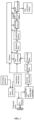
- the ultrasound apparatus includes the following components: A waveform generator: configured to generate a data signal, so that a pulse generator generates a transmission pulse according to the data signal.
- a transmitted beam former configured to implement electronic focusing and control over a sound beam from a multi-array-element ultrasound probe. It appropriately delays a transmitted signal for each array element, so that transmitter signals reach a target at the same time and produce the highest sound intensity at the target, that is, a strongest echo signal is obtained.
- a pulse generator configured to generate a transmission pulse.
- a T/R switch a transmit-receive switch configured to control the ultrasound probe to be currently in a transmission mode or reception mode.
- An ultrasound probe composed of a piezoelectric element, a connector and a supporting structure.
- the ultrasound probe converts electrical energy into mechanical energy in the transmission mode, and a mechanical wave generated is propagated to a medium.
- a reflected mechanical waveform is received, and converted into an electrical signal by the ultrasound probe.
- a TGC (Time Gain Compensate) gain an amplifier gain is controlled to increase with the deepening of a detection depth to compensate for attenuation of an ultrasound signal with a propagation distance.
- An analog-digital converter configured to convert an analog signal into a digital signal.
- a received beam former similar to the transmitted beam former, configured to implement electronic focusing and control over the sound beam from the multi-array-element ultrasound probe. It appropriately delays the received echo to implement linear superimposition of echo signals from multiple array elements to achieve the highest sensitivity.
- a matched filter a filter matched with transmission codes to achieve compression of the codes.
- a transversal filter configured to perform range sidelobe suppression on a received signal.
- a first processing unit configured to implement an addition, subtraction or bypass function.
- Bypass means that an information flow directly enters the next functional module.
- a memory configured to cache data, for example, caching a received echo signal or a processed echo signal.
- the memory may be a volatile memory, such as random-access memory (RAM); the memory may also include a non-volatile memory, such as a flash memory, a hard disk drive (HDD) or a solid-state drive (SSD); and the memory may also include a combination of the above types of memory.
- RAM random-access memory
- HDD hard disk drive
- SSD solid-state drive
- a bandpass filter configured to selectively filter out a desired frequency band from the received signal.
- An amplitude detector configured to detect the amplitude of the received signal.
- a second processing unit configured to implement addition and bypass functions.
- a logarithm compressor configured to perform logarithmic operations on the received signal.
- a third processing unit configured to implement a subtraction or bypass function.
- a scan convertor/display configured to perform data conversion and then display an ultrasound image.
- the waveform generator in a B-mode, the waveform generator generates a required broadband pulse.
- the pulse is appropriately delayed by the transmitted beam former before entering the pulse generator.
- the pulse generator generates a high-voltage pulse and sends it to the ultrasound probe.
- echo signals from the ultrasound probe are first amplified by the TGC (Time Gain Compensate) gain, and then converted into digital signals by the analog-digital converter, and the digital signals are delayed and added together by the received beam former.
- Beamforming may be implemented by one receiving line or a plurality of receiving lines.
- beamformed data directly enter the bandpass filter, that is, the first processing unit in the figure implements the bypass function (the bypass function described in this embodiment means skipping this unit and entering the next unit for processing), and the beamformed data directly enter the bandpass filter.
- the bypass function described in this embodiment means skipping this unit and entering the next unit for processing
- the beamformed data directly enter the bandpass filter.
- a tissue harmonic image there are two transmission pulses with opposite phases. Beamforming data from a first pulse are stored in the memory. When beamforming data from a second pulse appear, the system adds the beamforming data from the two pulses together, that is, the first processing unit in FIG. 1 implements the addition function. In this way, fundamental wave signals of the beamforming data from the two pulses are eliminated, and second harmonic signals are added together, the sum of the second harmonic signals enters the bandpass filter, and a signal processed by the bandpass filter is subjected to scan conversion processing.
- the waveform generator For a blood flow imaging mode, the waveform generator generates a coded pulse according to a predetermined code sequence, usually binary phase codes, such as Barker codes or Golay paired codes.
- the coded pulse is appropriately delayed by the transmitted beam former before entering the pulse generator.
- the pulse generator generates a high-voltage coded pulse and sends it to the ultrasound probe.
- An echo signal received from the ultrasound probe is first amplified by the TGC, and then converted into a digital signal by the analog-digital converter. Since the transmitted pulse is coded, the echo signal received by the probe contains coded information, that is, the signal is a coded echo signal. These digitized coded echo signals are delayed and added together by the received beam former.
- a pulse compression (or decoding) process of the beamforming data is implemented by a matched filter and a transversal filter.
- the RSL (Range Sidelobe) level of the matched filter Barker codes is a few decibels lower than a main peak, and thus the transversal filter is provided to reduce the RSL to 30 decibels or lower, that is, the transversal filter is used to achieve range sidelobe suppression.
- the decoded signal may be stored in the memory, and may also be subjected to addition, subtraction or bypass processing by the first processing unit.
- the transmission coding sequence is Golay paired codes
- a pair of Golay codes is transmitted separately, and a pulse compression process of the beamforming data is a matching and summing process by the matched filter.
- a first Golay-coded beamforming data are subjected to matched filtering and stored in the memory.
- a second Golay-coded beamforming data are matched, filtered and summed with the first data in the memory.
- the transversal filter is bypassed.
- Barker codes has the advantage of a single transmission operation, but requires an additional filter to suppress the RSL.
- Using the Golay paired codes can completely balance out the RSL, but requires two transmission operations, which reduces the frame rate.
- the echo signals in the B-mode and the blood flow imaging mode are subjected to bandpass filtering.
- the bandpass filter keeps the echo signals in a required frequency band and suppresses noise outside the frequency band, which is conducive to improving the signal-to-noise ratio.
- the amplitudes of the echo signals are calculated by removing a carrier frequency.
- the detected amplitudes may be stored in the memory, and may also be summed by the second processing unit.
- the processed data are output by the second processing unit and stored in the memory.
- the third processing unit may also be used for subtraction/bypass processing.
- the first processing unit, the second processing unit and the third processing unit may respectively correspond to processors, or at least two processing units may correspond to one processor, which is not limited in this embodiment.
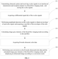
- FIG. 2 shows a method flow chart of an ultrasound imaging method according to some embodiments of the present disclosure, which is used in the ultrasound apparatus shown in FIG. 1 . As shown in FIG. 2 , the method includes the following steps.
- ultrasound pulses are transmitted and n echo signals are received in an interleaved transmission and reception manner in a blood flow imaging mode, and the n echo signals are stored.
- the ultrasound apparatus sets pulse repetition time PRT between two consecutive transmission operations to ⁇ according to a blood flow velocity.
- a minimum PRT ( ⁇ min ) is equal to the time required for one transmission and reception operation.
- ⁇ needs to be increased so that a change of a phase of a Doppler frequency shift signal from one pulse to the next pulse can be measured.
- simply increasing ⁇ will reduce the frame rate of the ultrasound image and decrease the signal-to-noise ratio. Therefore, in conjunction with FIG. 3 , pulse signals are transmitted in an interleaved transmission manner in this embodiment.
- the ultrasound probe enables a first transmission and reception operation of a first group of receiving lines.
- the number of receiving lines in each group is i, wherein i ⁇ 1, and reception of the first group of receiving lines is completed after waiting time ⁇ min .
- the ultrasound probe enables a transmission and reception process for a second group of receiving lines without waiting for the time ⁇ .
- the ultrasound probe operates in such a repeated manner until a first transmission and reception operation of an m-th group of receiving lines is completed.
- the ultrasound probe enables a second transmission and reception operation of the first group of receiving lines, and operates in such a repeated manner until a second transmission and reception operation of the m-th group is completed. This process continues until an n-th transmission and reception operation of the m-th group of receiving lines.
- the ultrasound probe moves to an (m+1)th group of receiving lines, and repeat the interleaving process in a similar transmission and reception manner as described above.
- echo signals of the n ultrasound pulses are e 1 ( t ) , e 2 ( t ) , ..., e n ( t ) , respectively.
- the number of ultrasound pulses transmitted may be greater than the number of echo signals received, and this is not limited here.
- ultrasound pulses may be transmitted to the breast, blood vessels, or any tissue in the above-mentioned interleaved transmission and reception manner, which is not limited in this embodiment.
- a differential signal d(t) of the n echo signals is acquired.
- echo signals e 1 ( t ) and e 2 ( t ) formed by two beams can be received after two coded pulses are transmitted.
- TGC gain and analog-digital conversion referring to the above description, in the case where Barker codes are used for coded transmission, the echo signals are filtered by the matched filter and subjected to range sidelobe suppression by the transversal filter, and in the case of Golay-coded transmission, the echo signals are only filtered by the matched filter, and bypass the transversal filter, and e 1 ( t ) subjected to the above processing is stored in the memory.
- the first processing unit executes subtraction e 1 ( t ) - e 2 ( t ) by calling e 1 ( t ) from the memory to obtain d(t), and after d(t) is calculated, d(t) is stored in the memory.
- the ultrasound probe transmits three coded pulses and receives echoes e 1 ( t ) , e 2 ( t ) and e 3 ( t ) formed by three beams.
- the processede 1 ( t ) is stored in the memory, and at the same time, is subjected to amplitude detection to obtain
- e 2 ( t ) is processed, in conjunction with FIG. 1 , the first processing unit calculates e 1 ( t ) - 2 e 2 ( t ) by calling e 1 ( t ) from the memory and stores the result in the memory.
- e 2 ( t ) is subjected to amplitude detection to obtain
- the first processing unit adds e 3 ( t ) to e 1 ( t ) - 2 e 2 ( t ) in the memory to implement second-order filtering of e 1 ( t ) - 2 e 2 ( t ) + e 3 ( t ) to obtain d ( t ) .
- amplitude detection is performed on the n echo signals to obtain an envelope of each echo signal, and a sum B(t) of the envelopes of the echo signals is acquired;
- e 1 ( t ) is processed and then stored in the memory.
- e 2 ( t ) is obtained, e 2 ( t ) is filtered by the bandpass filter and subjected to amplitude detection to obtain
- the second processing unit adds
- e 1 ( t ) is processed and then stored in the memory, and at the same time, e 1 ( t ) is subjected to amplitude detection to obtain
- e 2 ( t ) is processed, e 2 ( t ) is filtered by the bandpass filter and then subjected to amplitude detection to obtain
- e 3 ( t ) is filtered by the bandpass filter and subjected to amplitude detection to obtain
- the second processing unit adds
- image gray intensity of the blood flow imaging mode is calculated according to d(t) and B(t).
- logarithmic compression can also be performed on d t B t , and the image gray intensity is represented by a value after the logarithmic compression.
- ) of the blood flow mode is obtained by the third processing unit.
- this step includes: First, the value of the B(t) is updated according to a magnitude relationship between the B(t) and a preset threshold N thold .
- image gray intensity of the blood flow imaging mode is calculated according to the d ( t ) and the updated B ( t ) .
- the image gray intensity of S-Slow can be calculated according to d ( t ) and the updated B ( t ) .
- the specific calculation method is as described above, and will not be repeated here.
- n 2 or 3.
- calculation can be performed in a similar calculation manner as described above, which is not repeated here.
- step 105 B-mode ultrasound echo data are acquired.
- the ultrasound apparatus can also transmit pulses through the ultrasound probe to obtain the B-mode ultrasound echo data.
- the B-mode data and the blood flow imaging mode data are acquired and processed differently, that is, B-mode ultrasound echo data and blood flow imaging mode echo can be obtained through different sequence pulses.
- B-mode receiving lines and blood flow imaging mode receiving lines may be obtained alternately until a complete B-mode image and blood flow imaging mode image is obtained.
- one frame of B-mode image and one frame of blood flow imaging mode image may also be obtained alternately.
- one frame of B-mode image and multiple frames of blood flow imaging mode images may be obtained alternately.
- harmonic data or fundamental wave data can be obtained, which is not limited in this embodiment.
- step 106 scan conversion is performed on the B-mode ultrasound echo data and the calculated image gray intensity of the blood flow imaging mode, and an ultrasound image is displayed according to a conversion result.
- the B-mode ultrasound image and the blood flow imaging mode image can be displayed separately, and can also be displayed side by side, and of course, can also be displayed in combination.
- This embodiment is described by using an example of displaying a combination of the B-mode ultrasound echo data and the blood flow imaging mode image data, after acquiring the B-mode ultrasound echo data and the blood flow imaging mode image data.
- the step includes: combining the B-mode ultrasound echo data and the image of the blood flow imaging mode, and displaying the combined ultrasound image.
- the ways of combining the images includes: determining brightness of the combined ultrasound image according to a magnitude relationship between brightness of the image of the blood flow imaging mode and a brightness threshold, and the B-mode ultrasound echo data.
- brightness X B of a B-mode ultrasound image and brightness X S-Flow of the image of the blood flow imaging mode are acquired.
- X X B when X S-Flow ⁇ threshold S-Flow , wherein X is the brightness of the combined image, wherein threshold S-Flow is a minimum brightness level threshold of the blood flow imaging mode, and signals below threshold S-Flow are all regarded as non-blood flow imaging mode signals.
- FIG. 4 which shows an ultrasound blood flow image obtained by using an existing method.
- the obtained ultrasound blood flow image is not smooth enough and has artifacts to some degree.
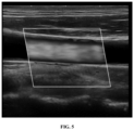
- FIG. 5 which shows an ultrasound blood flow image obtained by using the method of this embodiment, the ultrasound blood flow image obtained by using the method of this embodiment is obviously smoother, and artifacts are largely eliminated.
- the ultrasound imaging device calculates the differential signal d(t) of the n echo signals and the sum B(t) of the envelopes of the echo signals, then calculates the image gray intensity of the blood flow imaging mode according to d(t) and B(t), and displays the ultrasound image according to the B-mode ultrasound echo data and the calculated image gray intensity during ultrasound imaging.
- the problem of artifacts in the ultrasound image in the prior art is solved, and artifacts in the image caused by tissue movement flickering and weak blood flow can be eliminated.
- the difference between the logarithmic values of d(t) and B(t) is calculated to calculate the image gray intensity, thus achieving an effect of low processing complexity by simple subtraction while eliminating the artifacts.
- This embodiment further provides an ultrasound device including: a memory and a processor, the memory storing at least one program instruction, and the processor loading and executing the at least one program instruction to implement the above-mentioned ultrasound imaging method.
- This embodiment further discloses an ultrasound system including the above-mentioned ultrasound imaging device.
- This embodiment further discloses a breast ultrasound apparatus including the ultrasound imaging device of the first aspect, the breast ultrasound apparatus being used to achieve the following functions:
- An embodiment of the present disclosure further provides a non-transitory computer readable storage medium that stores a set of computer executable instructions, and the computer executable instructions may be executed for performing the ultrasound imaging methods in any of the above method embodiments.
- the storage medium may be a magnetic disk, an optical disk, a read-only memory (ROM), a random-access memory (RAM), a flash memory, a hard disk drive (HDD), a solid-state drive (SSD), or the like; and the storage medium may also include a combination of the aforementioned types of memory.
Landscapes
- Health & Medical Sciences (AREA)
- Life Sciences & Earth Sciences (AREA)
- Engineering & Computer Science (AREA)
- Physics & Mathematics (AREA)
- Heart & Thoracic Surgery (AREA)
- Surgery (AREA)
- Nuclear Medicine, Radiotherapy & Molecular Imaging (AREA)
- Pathology (AREA)
- Radiology & Medical Imaging (AREA)
- Biomedical Technology (AREA)
- Veterinary Medicine (AREA)
- Medical Informatics (AREA)
- Molecular Biology (AREA)
- Biophysics (AREA)
- Animal Behavior & Ethology (AREA)
- General Health & Medical Sciences (AREA)
- Public Health (AREA)
- Computer Vision & Pattern Recognition (AREA)
- Hematology (AREA)
- Gynecology & Obstetrics (AREA)
- General Physics & Mathematics (AREA)
- Theoretical Computer Science (AREA)
- Ultra Sonic Daignosis Equipment (AREA)
Claims (10)
- Ultraschallbildgebungseinrichtung, umfassend: einen Speicher und einen Prozessor, wobei der Speicher zumindest eine Programmanweisung speichert und der Prozessor die zumindest eine Programmanweisung lädt und ausführt, um ein Verfahren zu implementieren, das die folgenden Schritte umfasst:Übertragen von Ultraschallimpulsen und Empfangen von n Echosignalen in einer verschachtelten Übertragungs- und Empfangsweise in einem Blutflussbildgebungsmodus (101), wobei n eine ganze Zahl größer als 1 ist;Erfassen eines Differenzsignals d(t) der n Echosignale (102);Durchführen von Amplitudendetektion an den n Echosignalen, um eine Hülle jedes Echosignals zu erhalten, und Erfassen einer Summe B(t) der Hüllen der Echosignale (103);Berechnen von Bildgrauintensität des Blutflussbildgebungsmodus gemäß d(t) und B(t) (104) durch Aktualisieren des Wertes von B(t) gemäß einer Größenbeziehung zwischen B(t) und einem voreingestellten Schwellenwert Nthold, und Berechnen der Bildgrauintensität des Blutflussbildgebungsmodus gemäß d(t) und dem aktualisierten Wert von B(t);Erfassen von B-Modus-Ultraschallechodaten (105); undDurchführen von Scanumwandlung an den B-Modus-Ultraschallechodaten und der berechneten Bildgrauintensität des Blutflussbildgebungsmodus und Anzeigen eines Ultraschallbildes gemäß einem Umwandlungsergebnis (106), umfassend die folgenden Schritte:Kombinieren der B-Modus-Ultraschallechodaten und eines Bildes des Blutflussbildgebungsmodus und Anzeigen des kombinierten Ultraschallbildes; oderAnzeigen eines B-Modus-Ultraschallbildes gemäß den B-Modus-Ultraschallechodaten und Anzeigen eines Blutflussbildes gemäß der Bildgrauintensität des Blutflussbildgebungsmodus.
- Einrichtung nach Anspruch 1, wobei der Schritt des Übertragens von Ultraschallimpulsen in einer verschachtelten Übertragungs- und Empfangsweise in einem Blutflussbildgebungsmodus Folgendes umfasst:Ermöglichen von Übertragung und Empfang einer j-ten Gruppe von Empfangsleitungen, wobei ein Anfangswert von j 1 ist; undSetzen von j+1, nachdem der Empfang der j-ten Gruppe von Empfangsleitungen abgeschlossen ist, und sofortiges Ausführen des Schrittes des Ermöglichens von Übertragung und Empfang der j-ten Gruppe von Empfangsleitungen.
- Einrichtung nach Anspruch 1, wobei der Schritt des Aktualisierens des Wertes von B(t) gemäß einer Größenbeziehung zwischen B(t) und einem voreingestellten Schwellenwert Nthold Folgendes umfasst:
Ansehen von Nthold als den aktualisierten B(t) unter der Bedingung, dass B(t)<Nthold. - Einrichtung nach Anspruch 1, wobei der Schritt des Berechnens von Bildgrauintensität des Blutflussbildgebungsmodus gemäß dem d(t) und dem aktualisierten B(t) Folgendes umfasst:Berechnen von Bildgrauintensität des Blutflussbildgebungsmodus als

oderBerechnen von Bildgrauintensität des Blutflussbildgebungsmodus als
- Einrichtung nach Anspruch 1, wobei der Schritt des Kombinierens der B-Modus-Ultraschallechodaten und eines Bildes des Blutflussbildgebungsmodus und des Anzeigens des kombinierten Ultraschallbildes Folgendes umfasst:
Bestimmen von Helligkeit des kombinierten Ultraschallbildes gemäß einer Größenbeziehung zwischen Helligkeit des Bildes des Blutflussbildgebungsmodus und einem Helligkeitsschwellenwert und den B-Modus-Ultraschallechodaten. - Einrichtung nach Anspruch 5, wobei der Schritt des Bestimmens von Helligkeit des kombinierten Ultraschallbildes gemäß einer Größenbeziehung zwischen Helligkeit des Bildes des Blutflussbildgebungsmodus und einem Helligkeitsschwellenwert und den B-Modus-Ultraschallechodaten Folgendes umfasst:Erfassen von Helligkeit XB des B-Modus-Ultraschallbildes und Helligkeit XS-Flow des Bildes des Blutflussbildgebungsmodus,Bestimmen, dass X = XB, wenn XS-Flow ≤ SchwellenwertS-Flow, wobei X die Helligkeit des kombinierten Ultraschallbildes ist; undBestimmen, dass X = XS-F + αXB /256, wenn XS-Flow > SchwellenwertS-Flow, wobei α ein Koeffizient ist,wobei SchwellenwertS-Flow ein Mindesthelligkeitsniveauschwellenwert des Blutflussbildgebungsmodus ist.
- Einrichtung nach Anspruch 6, wobei α eines von Folgendem ist:


- Einrichtung nach einem der Ansprüche 1 bis 7, wobei das Verfahren ferner Folgendes umfasst:Erhalten von B-Modus-Empfangsleitungen und Blutflussbildgebungsmodus-Empfangsleitungen abwechselnd, bis ein vollständiges B-Modus-Bild und Blutflussbildgebungsmodusbild erhalten ist, wenn die n Echosignale und die B-Modus-Ultraschallechodaten erfasst werden; oderErhalten eines Rahmens von B-Modus-Bild und mehrerer Rahmen von Blutflussbildgebungsmodusbildern abwechselnd, wenn die n Echosignale und die B-Modus-Ultraschallechodaten erfasst werden.
- Ultraschallsystem, umfassend die Ultraschallbildgebungseinrichtung nach einem der Ansprüche 1 bis 8.
- Brustultraschallvorrichtung, umfassend die Ultraschallbildgebungseinrichtung nach einem der Ansprüche 1 bis 8, wobei die Brustultraschallvorrichtung verwendet wird, um die folgenden Funktionen zu erreichen:Übertragen von Ultraschallimpulsen an einen Brustbereich und Empfangen von n Echosignalen in einer verschachtelten Übertragungs- und Empfangsweise in einem Blutflussbildgebungsmodus, wobei n eine ganze Zahl größer als 1 ist;Erfassen eines Differenzsignals d(t) der n Echosignale;Durchführen von Amplitudendetektion an den n Echosignalen, um eine Hülle jedes Echosignals zu erhalten, und Erfassen einer Summe B(t) der Hüllen der Echosignale;Berechnen von Bildgrauintensität des Blutflussbildgebungsmodus gemäß dem d(t) und dem B(t);Erfassen von B-Modus-Ultraschallechodaten; undDurchführen von Scanumwandlung an den B-Modus-Ultraschallechodaten und der berechneten Bildgrauintensität des Blutflussbildgebungsmodus und Anzeigen eines Ultraschallbildes gemäß einem Umwandlungsergebnis.
Applications Claiming Priority (2)
| Application Number | Priority Date | Filing Date | Title |
|---|---|---|---|
| CN202010525364.7A CN113768542B (zh) | 2020-06-10 | 2020-06-10 | 超声血流成像装置及超声设备 |
| PCT/CN2021/071228 WO2021248910A1 (zh) | 2020-06-10 | 2021-01-12 | 超声成像装置及系统和乳腺超声设备 |
Publications (3)
| Publication Number | Publication Date |
|---|---|
| EP3943012A1 EP3943012A1 (de) | 2022-01-26 |
| EP3943012A4 EP3943012A4 (de) | 2022-10-05 |
| EP3943012B1 true EP3943012B1 (de) | 2025-06-11 |
Family
ID=78834850
Family Applications (1)
| Application Number | Title | Priority Date | Filing Date |
|---|---|---|---|
| EP21742291.4A Active EP3943012B1 (de) | 2020-06-10 | 2021-01-12 | Ultraschallbildgebungsvorrichtung und -system und brustultraschalleinrichtung |
Country Status (4)
| Country | Link |
|---|---|
| US (1) | US12089998B2 (de) |
| EP (1) | EP3943012B1 (de) |
| CN (1) | CN113768542B (de) |
| WO (1) | WO2021248910A1 (de) |
Families Citing this family (2)
| Publication number | Priority date | Publication date | Assignee | Title |
|---|---|---|---|---|
| CN113768542B (zh) * | 2020-06-10 | 2022-11-08 | 无锡祥生医疗科技股份有限公司 | 超声血流成像装置及超声设备 |
| CN115919362B (zh) * | 2023-03-15 | 2023-05-30 | 深圳英美达医疗技术有限公司 | 超声成像系统的伪像去除方法、装置、设备及存储介质 |
Family Cites Families (25)
| Publication number | Priority date | Publication date | Assignee | Title |
|---|---|---|---|---|
| US4265126A (en) | 1979-06-15 | 1981-05-05 | General Electric Company | Measurement of true blood velocity by an ultrasound system |
| JPS61100237A (ja) * | 1984-10-23 | 1986-05-19 | 株式会社東芝 | 超音波診断装置 |
| JP2557410B2 (ja) * | 1987-09-22 | 1996-11-27 | 株式会社東芝 | 超音波ドプラ血流イメージング装置 |
| JPH0454943A (ja) * | 1990-06-26 | 1992-02-21 | Toshiba Corp | 超音波診断装置 |
| US5282471A (en) * | 1991-07-31 | 1994-02-01 | Kabushiki Kaisha Toshiba | Ultrasonic imaging system capable of displaying 3-dimensional angiogram in real time mode |
| US5363849A (en) * | 1994-01-26 | 1994-11-15 | Cardiovascular Imaging Systems, Inc. | Enhancing intravascular ultrasonic blood vessel image |
| US5609155A (en) * | 1995-04-26 | 1997-03-11 | Acuson Corporation | Energy weighted parameter spatial/temporal filter |
| US5833613A (en) * | 1996-09-27 | 1998-11-10 | Advanced Technology Laboratories, Inc. | Ultrasonic diagnostic imaging with contrast agents |
| US5860931A (en) * | 1997-10-10 | 1999-01-19 | Acuson Corporation | Ultrasound method and system for measuring perfusion |
| JP4116143B2 (ja) * | 1998-04-10 | 2008-07-09 | 株式会社東芝 | 超音波診断装置 |
| US6419632B1 (en) * | 1999-03-30 | 2002-07-16 | Kabushiki Kaisha Toshiba | High resolution flow imaging for ultrasound diagnosis |
| US6306091B1 (en) * | 1999-08-06 | 2001-10-23 | Acuson Corporation | Diagnostic medical ultrasound systems and methods utilizing estimation of 3-dimensional rigid body transformation |
| US6978876B1 (en) * | 1999-09-07 | 2005-12-27 | Otis Elevator Company | Step for escalator |
| JP4377495B2 (ja) * | 1999-10-29 | 2009-12-02 | 株式会社東芝 | 超音波診断装置 |
| JP2001212144A (ja) * | 2000-01-31 | 2001-08-07 | Toshiba Corp | 超音波診断装置及び超音波画像化方法 |
| US6749569B1 (en) * | 2003-01-07 | 2004-06-15 | Esaote S.P.A. | Method and apparatus for ultrasound imaging |
| JP4504004B2 (ja) * | 2003-12-17 | 2010-07-14 | 株式会社東芝 | 超音波診断装置 |
| WO2006088094A1 (ja) * | 2005-02-17 | 2006-08-24 | Matsushita Electric Industrial Co., Ltd. | 超音波ドプラ血流計 |
| JP4956210B2 (ja) | 2007-02-05 | 2012-06-20 | 株式会社東芝 | 超音波診断装置 |
| CN101336830B (zh) * | 2007-07-03 | 2012-07-04 | 深圳迈瑞生物医疗电子股份有限公司 | 用于超声诊断成像的正交多普勒信号间隙填充方法与装置 |
| CN102429684B (zh) * | 2010-09-28 | 2013-10-09 | 深圳迈瑞生物医疗电子股份有限公司 | 一种多普勒彩色血流成像方法和装置 |
| JP2012139489A (ja) | 2010-12-16 | 2012-07-26 | Toshiba Corp | 超音波診断装置及びその制御方法 |
| CN104143047B (zh) | 2014-07-21 | 2017-08-11 | 华北电力大学(保定) | 血管内超声灰阶图像的自动组织标定方法 |
| CN106102588B (zh) * | 2015-09-06 | 2019-04-23 | 深圳迈瑞生物医疗电子股份有限公司 | 超声灰阶成像系统及方法 |
| CN113768542B (zh) * | 2020-06-10 | 2022-11-08 | 无锡祥生医疗科技股份有限公司 | 超声血流成像装置及超声设备 |
-
2020
- 2020-06-10 CN CN202010525364.7A patent/CN113768542B/zh active Active
-
2021
- 2021-01-12 EP EP21742291.4A patent/EP3943012B1/de active Active
- 2021-01-12 US US17/423,175 patent/US12089998B2/en active Active
- 2021-01-12 WO PCT/CN2021/071228 patent/WO2021248910A1/zh not_active Ceased
Also Published As
| Publication number | Publication date |
|---|---|
| CN113768542A (zh) | 2021-12-10 |
| EP3943012A1 (de) | 2022-01-26 |
| US20230086369A1 (en) | 2023-03-23 |
| US12089998B2 (en) | 2024-09-17 |
| WO2021248910A1 (zh) | 2021-12-16 |
| CN113768542B (zh) | 2022-11-08 |
| EP3943012A4 (de) | 2022-10-05 |
Similar Documents
| Publication | Publication Date | Title |
|---|---|---|
| US12004898B2 (en) | Ultrasound gray-scale imaging system and method | |
| US6827686B2 (en) | System and method for improved harmonic imaging | |
| US6508767B2 (en) | Ultrasonic harmonic image segmentation | |
| US6277075B1 (en) | Method and apparatus for visualization of motion in ultrasound flow imaging using continuous data acquisition | |
| US8454517B2 (en) | Ultrasonic diagnostic apparatus and ultrasonic diagnostic method | |
| EP0948931B1 (de) | Ultraschallabbildung mittels kodierter Anregung beim Senden und selektiver Filterung beim Empfang | |
| EP1122556B1 (de) | Verbesserte gewebeerzeugte harmonische Bilddarstellung mit Verwendung von kodierter Anregung | |
| US6210332B1 (en) | Method and apparatus for flow imaging using coded excitation | |
| US8313436B2 (en) | Methods and apparatus for ultrasound imaging | |
| US5984869A (en) | Method and apparatus for ultrasonic beamforming using golay-coded excitation | |
| US7740583B2 (en) | Time delay estimation method and system for use in ultrasound imaging | |
| US6618493B1 (en) | Method and apparatus for visualization of motion in ultrasound flow imaging using packet data acquisition | |
| JP2001299764A (ja) | 超音波診断装置 | |
| EP2269091B1 (de) | Bilderzeugungsverfahren mit ultraschall und fehlerkorrekturverfahren dafür | |
| US6599248B1 (en) | Method and apparatus for ultrasound diagnostic imaging | |
| JP4405182B2 (ja) | 超音波診断装置 | |
| EP3943012B1 (de) | Ultraschallbildgebungsvorrichtung und -system und brustultraschalleinrichtung | |
| JP4445255B2 (ja) | 組織で発生される高調波との広帯域周波数合成を用いた超音波スペックル低減の方法及び装置 | |
| US20240111046A1 (en) | Method and system for flow processing on channel data for application of nonlinear beamforming | |
| CN115607185B (zh) | 超声成像方法和超声成像系统 | |
| US6533728B1 (en) | Method and apparatus for recovery and parametric display of contrast agents in ultrasound imaging | |
| JP2001000434A (ja) | 物質をイメージングする方法及びイメージング・システム | |
| US12611171B2 (en) | System, method and/or computer readable medium for adaptive spatial compounding in ultrasound based on probabilities determined from an estimated SNR | |
| US12436279B2 (en) | Ultrasound imaging method and ultrasound imaging system | |
| JPH0716227A (ja) | 超音波パルスドプラ診断装置 |
Legal Events
| Date | Code | Title | Description |
|---|---|---|---|
| STAA | Information on the status of an ep patent application or granted ep patent |
Free format text: STATUS: UNKNOWN |
|
| STAA | Information on the status of an ep patent application or granted ep patent |
Free format text: STATUS: THE INTERNATIONAL PUBLICATION HAS BEEN MADE |
|
| PUAI | Public reference made under article 153(3) epc to a published international application that has entered the european phase |
Free format text: ORIGINAL CODE: 0009012 |
|
| STAA | Information on the status of an ep patent application or granted ep patent |
Free format text: STATUS: REQUEST FOR EXAMINATION WAS MADE |
|
| 17P | Request for examination filed |
Effective date: 20210727 |
|
| AK | Designated contracting states |
Kind code of ref document: A1 Designated state(s): AL AT BE BG CH CY CZ DE DK EE ES FI FR GB GR HR HU IE IS IT LI LT LU LV MC MK MT NL NO PL PT RO RS SE SI SK SM TR |
|
| A4 | Supplementary search report drawn up and despatched |
Effective date: 20220907 |
|
| RIC1 | Information provided on ipc code assigned before grant |
Ipc: A61B 8/08 20060101ALI20220901BHEP Ipc: A61B 8/00 20060101ALI20220901BHEP Ipc: A61B 8/06 20060101AFI20220901BHEP |
|
| DAV | Request for validation of the european patent (deleted) | ||
| DAX | Request for extension of the european patent (deleted) | ||
| GRAP | Despatch of communication of intention to grant a patent |
Free format text: ORIGINAL CODE: EPIDOSNIGR1 |
|
| STAA | Information on the status of an ep patent application or granted ep patent |
Free format text: STATUS: GRANT OF PATENT IS INTENDED |
|
| RIC1 | Information provided on ipc code assigned before grant |
Ipc: A61B 8/08 20060101ALI20241212BHEP Ipc: A61B 8/00 20060101ALI20241212BHEP Ipc: A61B 8/06 20060101AFI20241212BHEP |
|
| INTG | Intention to grant announced |
Effective date: 20250107 |
|
| GRAS | Grant fee paid |
Free format text: ORIGINAL CODE: EPIDOSNIGR3 |
|
| GRAA | (expected) grant |
Free format text: ORIGINAL CODE: 0009210 |
|
| STAA | Information on the status of an ep patent application or granted ep patent |
Free format text: STATUS: THE PATENT HAS BEEN GRANTED |
|
| AK | Designated contracting states |
Kind code of ref document: B1 Designated state(s): AL AT BE BG CH CY CZ DE DK EE ES FI FR GB GR HR HU IE IS IT LI LT LU LV MC MK MT NL NO PL PT RO RS SE SI SK SM TR |
|
| REG | Reference to a national code |
Ref country code: GB Ref legal event code: FG4D |
|
| REG | Reference to a national code |
Ref country code: CH Ref legal event code: EP |
|
| REG | Reference to a national code |
Ref country code: IE Ref legal event code: FG4D |
|
| REG | Reference to a national code |
Ref country code: DE Ref legal event code: R096 Ref document number: 602021032142 Country of ref document: DE |
|
| PG25 | Lapsed in a contracting state [announced via postgrant information from national office to epo] |
Ref country code: ES Free format text: LAPSE BECAUSE OF FAILURE TO SUBMIT A TRANSLATION OF THE DESCRIPTION OR TO PAY THE FEE WITHIN THE PRESCRIBED TIME-LIMIT Effective date: 20250611 Ref country code: FI Free format text: LAPSE BECAUSE OF FAILURE TO SUBMIT A TRANSLATION OF THE DESCRIPTION OR TO PAY THE FEE WITHIN THE PRESCRIBED TIME-LIMIT Effective date: 20250611 |
|
| REG | Reference to a national code |
Ref country code: LT Ref legal event code: MG9D |
|
| PG25 | Lapsed in a contracting state [announced via postgrant information from national office to epo] |
Ref country code: GR Free format text: LAPSE BECAUSE OF FAILURE TO SUBMIT A TRANSLATION OF THE DESCRIPTION OR TO PAY THE FEE WITHIN THE PRESCRIBED TIME-LIMIT Effective date: 20250912 Ref country code: NO Free format text: LAPSE BECAUSE OF FAILURE TO SUBMIT A TRANSLATION OF THE DESCRIPTION OR TO PAY THE FEE WITHIN THE PRESCRIBED TIME-LIMIT Effective date: 20250911 |
|
| REG | Reference to a national code |
Ref country code: NL Ref legal event code: MP Effective date: 20250611 |
|
| PG25 | Lapsed in a contracting state [announced via postgrant information from national office to epo] |
Ref country code: BG Free format text: LAPSE BECAUSE OF FAILURE TO SUBMIT A TRANSLATION OF THE DESCRIPTION OR TO PAY THE FEE WITHIN THE PRESCRIBED TIME-LIMIT Effective date: 20250611 |
|
| PG25 | Lapsed in a contracting state [announced via postgrant information from national office to epo] |
Ref country code: HR Free format text: LAPSE BECAUSE OF FAILURE TO SUBMIT A TRANSLATION OF THE DESCRIPTION OR TO PAY THE FEE WITHIN THE PRESCRIBED TIME-LIMIT Effective date: 20250611 |
|
| PG25 | Lapsed in a contracting state [announced via postgrant information from national office to epo] |
Ref country code: RS Free format text: LAPSE BECAUSE OF FAILURE TO SUBMIT A TRANSLATION OF THE DESCRIPTION OR TO PAY THE FEE WITHIN THE PRESCRIBED TIME-LIMIT Effective date: 20250911 |
|
| PG25 | Lapsed in a contracting state [announced via postgrant information from national office to epo] |
Ref country code: LV Free format text: LAPSE BECAUSE OF FAILURE TO SUBMIT A TRANSLATION OF THE DESCRIPTION OR TO PAY THE FEE WITHIN THE PRESCRIBED TIME-LIMIT Effective date: 20250611 |
|
| PG25 | Lapsed in a contracting state [announced via postgrant information from national office to epo] |
Ref country code: NL Free format text: LAPSE BECAUSE OF FAILURE TO SUBMIT A TRANSLATION OF THE DESCRIPTION OR TO PAY THE FEE WITHIN THE PRESCRIBED TIME-LIMIT Effective date: 20250611 |
|
| PG25 | Lapsed in a contracting state [announced via postgrant information from national office to epo] |
Ref country code: PT Free format text: LAPSE BECAUSE OF FAILURE TO SUBMIT A TRANSLATION OF THE DESCRIPTION OR TO PAY THE FEE WITHIN THE PRESCRIBED TIME-LIMIT Effective date: 20251013 |
|
| REG | Reference to a national code |
Ref country code: AT Ref legal event code: MK05 Ref document number: 1801745 Country of ref document: AT Kind code of ref document: T Effective date: 20250611 |
|
| PG25 | Lapsed in a contracting state [announced via postgrant information from national office to epo] |
Ref country code: IS Free format text: LAPSE BECAUSE OF FAILURE TO SUBMIT A TRANSLATION OF THE DESCRIPTION OR TO PAY THE FEE WITHIN THE PRESCRIBED TIME-LIMIT Effective date: 20251011 |
|
| PG25 | Lapsed in a contracting state [announced via postgrant information from national office to epo] |
Ref country code: AT Free format text: LAPSE BECAUSE OF FAILURE TO SUBMIT A TRANSLATION OF THE DESCRIPTION OR TO PAY THE FEE WITHIN THE PRESCRIBED TIME-LIMIT Effective date: 20250611 Ref country code: SM Free format text: LAPSE BECAUSE OF FAILURE TO SUBMIT A TRANSLATION OF THE DESCRIPTION OR TO PAY THE FEE WITHIN THE PRESCRIBED TIME-LIMIT Effective date: 20250611 |
|
| PG25 | Lapsed in a contracting state [announced via postgrant information from national office to epo] |
Ref country code: CZ Free format text: LAPSE BECAUSE OF FAILURE TO SUBMIT A TRANSLATION OF THE DESCRIPTION OR TO PAY THE FEE WITHIN THE PRESCRIBED TIME-LIMIT Effective date: 20250611 |
|
| PG25 | Lapsed in a contracting state [announced via postgrant information from national office to epo] |
Ref country code: PL Free format text: LAPSE BECAUSE OF FAILURE TO SUBMIT A TRANSLATION OF THE DESCRIPTION OR TO PAY THE FEE WITHIN THE PRESCRIBED TIME-LIMIT Effective date: 20250611 |
|
| PG25 | Lapsed in a contracting state [announced via postgrant information from national office to epo] |
Ref country code: EE Free format text: LAPSE BECAUSE OF FAILURE TO SUBMIT A TRANSLATION OF THE DESCRIPTION OR TO PAY THE FEE WITHIN THE PRESCRIBED TIME-LIMIT Effective date: 20250611 |
|
| PG25 | Lapsed in a contracting state [announced via postgrant information from national office to epo] |
Ref country code: RO Free format text: LAPSE BECAUSE OF FAILURE TO SUBMIT A TRANSLATION OF THE DESCRIPTION OR TO PAY THE FEE WITHIN THE PRESCRIBED TIME-LIMIT Effective date: 20250611 Ref country code: SK Free format text: LAPSE BECAUSE OF FAILURE TO SUBMIT A TRANSLATION OF THE DESCRIPTION OR TO PAY THE FEE WITHIN THE PRESCRIBED TIME-LIMIT Effective date: 20250611 |
|
| PG25 | Lapsed in a contracting state [announced via postgrant information from national office to epo] |
Ref country code: DK Free format text: LAPSE BECAUSE OF FAILURE TO SUBMIT A TRANSLATION OF THE DESCRIPTION OR TO PAY THE FEE WITHIN THE PRESCRIBED TIME-LIMIT Effective date: 20250611 |
|
| PGFP | Annual fee paid to national office [announced via postgrant information from national office to epo] |
Ref country code: DE Payment date: 20260217 Year of fee payment: 6 |
|
| PG25 | Lapsed in a contracting state [announced via postgrant information from national office to epo] |
Ref country code: IT Free format text: LAPSE BECAUSE OF FAILURE TO SUBMIT A TRANSLATION OF THE DESCRIPTION OR TO PAY THE FEE WITHIN THE PRESCRIBED TIME-LIMIT Effective date: 20250611 |
|
| PLBE | No opposition filed within time limit |
Free format text: ORIGINAL CODE: 0009261 |
|
| STAA | Information on the status of an ep patent application or granted ep patent |
Free format text: STATUS: NO OPPOSITION FILED WITHIN TIME LIMIT |
|
| PGFP | Annual fee paid to national office [announced via postgrant information from national office to epo] |
Ref country code: FR Payment date: 20260130 Year of fee payment: 6 |
|
| REG | Reference to a national code |
Ref country code: CH Ref legal event code: L10 Free format text: ST27 STATUS EVENT CODE: U-0-0-L10-L00 (AS PROVIDED BY THE NATIONAL OFFICE) Effective date: 20260423 |