EP3943260A1 - Dispositif et procédé de fabrication d'un capuchon de fermeture - Google Patents
Dispositif et procédé de fabrication d'un capuchon de fermeture Download PDFInfo
- Publication number
- EP3943260A1 EP3943260A1 EP21020251.1A EP21020251A EP3943260A1 EP 3943260 A1 EP3943260 A1 EP 3943260A1 EP 21020251 A EP21020251 A EP 21020251A EP 3943260 A1 EP3943260 A1 EP 3943260A1
- Authority
- EP
- European Patent Office
- Prior art keywords
- closure cap
- connecting flange
- carrier
- retaining ring
- section
- Prior art date
- Legal status (The legal status is an assumption and is not a legal conclusion. Google has not performed a legal analysis and makes no representation as to the accuracy of the status listed.)
- Granted
Links
Images


Classifications
-
- B—PERFORMING OPERATIONS; TRANSPORTING
- B26—HAND CUTTING TOOLS; CUTTING; SEVERING
- B26D—CUTTING; DETAILS COMMON TO MACHINES FOR PERFORATING, PUNCHING, CUTTING-OUT, STAMPING-OUT OR SEVERING
- B26D1/00—Cutting through work characterised by the nature or movement of the cutting member or particular materials not otherwise provided for; Apparatus or machines therefor; Cutting members therefor
- B26D1/01—Cutting through work characterised by the nature or movement of the cutting member or particular materials not otherwise provided for; Apparatus or machines therefor; Cutting members therefor involving a cutting member which does not travel with the work
- B26D1/02—Cutting through work characterised by the nature or movement of the cutting member or particular materials not otherwise provided for; Apparatus or machines therefor; Cutting members therefor involving a cutting member which does not travel with the work having a stationary cutting member
- B26D1/03—Cutting through work characterised by the nature or movement of the cutting member or particular materials not otherwise provided for; Apparatus or machines therefor; Cutting members therefor involving a cutting member which does not travel with the work having a stationary cutting member with a plurality of cutting members
- B26D1/035—Cutting through work characterised by the nature or movement of the cutting member or particular materials not otherwise provided for; Apparatus or machines therefor; Cutting members therefor involving a cutting member which does not travel with the work having a stationary cutting member with a plurality of cutting members for thin material, e.g. for sheets, strips or the like
-
- B—PERFORMING OPERATIONS; TRANSPORTING
- B26—HAND CUTTING TOOLS; CUTTING; SEVERING
- B26D—CUTTING; DETAILS COMMON TO MACHINES FOR PERFORATING, PUNCHING, CUTTING-OUT, STAMPING-OUT OR SEVERING
- B26D7/00—Details of apparatus for cutting, cutting-out, stamping-out, punching, perforating, or severing by means other than cutting
- B26D7/01—Means for holding or positioning work
-
- B—PERFORMING OPERATIONS; TRANSPORTING
- B26—HAND CUTTING TOOLS; CUTTING; SEVERING
- B26D—CUTTING; DETAILS COMMON TO MACHINES FOR PERFORATING, PUNCHING, CUTTING-OUT, STAMPING-OUT OR SEVERING
- B26D7/00—Details of apparatus for cutting, cutting-out, stamping-out, punching, perforating, or severing by means other than cutting
- B26D7/06—Arrangements for feeding or delivering work of other than sheet, web, or filamentary form
-
- B—PERFORMING OPERATIONS; TRANSPORTING
- B26—HAND CUTTING TOOLS; CUTTING; SEVERING
- B26D—CUTTING; DETAILS COMMON TO MACHINES FOR PERFORATING, PUNCHING, CUTTING-OUT, STAMPING-OUT OR SEVERING
- B26D7/00—Details of apparatus for cutting, cutting-out, stamping-out, punching, perforating, or severing by means other than cutting
- B26D7/08—Means for treating work or cutting member to facilitate cutting
- B26D7/10—Means for treating work or cutting member to facilitate cutting by heating
-
- B—PERFORMING OPERATIONS; TRANSPORTING
- B26—HAND CUTTING TOOLS; CUTTING; SEVERING
- B26D—CUTTING; DETAILS COMMON TO MACHINES FOR PERFORATING, PUNCHING, CUTTING-OUT, STAMPING-OUT OR SEVERING
- B26D1/00—Cutting through work characterised by the nature or movement of the cutting member or particular materials not otherwise provided for; Apparatus or machines therefor; Cutting members therefor
- B26D1/0006—Cutting members therefor
- B26D2001/006—Cutting members therefor the cutting blade having a special shape, e.g. a special outline, serrations
-
- B—PERFORMING OPERATIONS; TRANSPORTING
- B26—HAND CUTTING TOOLS; CUTTING; SEVERING
- B26F—PERFORATING; PUNCHING; CUTTING-OUT; STAMPING-OUT; SEVERING BY MEANS OTHER THAN CUTTING
- B26F2210/00—Perforating, punching, cutting-out, stamping-out, severing by means other than cutting of specific products
- B26F2210/04—Making plastic pilferproof screw caps by cutting a tamper ring
Definitions
- the invention relates to a device for producing a closure cap on a connecting flange, for example a screw cap on the neck of a plastic bottle.
- the screw cap of a plastic bottle which is typically designed as a plastic cap, should still be connected to the bottle after it has been opened, in order to prevent the screw cap from getting into the environment.
- the screw cap forms a closure cap consisting of a retaining ring and a plastic lid formed in one piece with the retaining ring, one or more slots being introduced between the retaining ring and the lid, which allow the lid to move relative to the retaining ring when it is screwed on.
- the retaining ring sits on a connecting flange which is located on the bottle neck of the plastic bottle and is connected to it.
- the introduction of one or more slits between the retaining ring and the cover is automated in Devices in which the cap, retaining ring and lid are received and provided with the desired slits or tear lines in an automated process.
- a device is for example in EP 1 021 282 B1 or EP 0 619 168 A1 described.
- the closure cap is placed on the connecting flange in a further assembly device.
- the object of the invention is to simplify the manufacture of closure caps which are seated on a connecting flange and are formed with a retaining ring and a lid.
- closure caps which are seated on a connecting flange with an opening and have a retaining ring and a cover which is formed in one piece with the retaining ring and is connected to the retaining ring.
- closure caps are placed, for example, as a screw cap on plastic bottles or on plasticized cardboard containers and are opened by turning the lid, which is designed as a screw cap, with the relative movement of the lid being made possible due to slots between the lid and the retaining ring.
- closure caps which are designed with a retaining ring and a cover can also be considered, with the cover not being able to be opened by turning but by tilting or snapping open about a transverse axis. In this case, too, the opened lid remains connected to the retaining ring.
- the transverse axis resides in a hinge formed by one or more slots between the retaining ring and the lid.
- sealing cap and connecting flange can be connected to a bottle or a beverage container.
- the connecting flange forms a connecting and carrier part which, on the one hand, is the carrier of the closure cap and, on the other hand, connects the closure cap to the bottle or beverage container.
- the device according to the invention enables the closure cap to be assembled with the connecting flange in an assembly section, in that the closure cap, consisting of a retaining ring and a cover formed in one piece with the retaining ring, is placed on the connecting flange before slots are made for the retaining ring and cover in the assembly section and thereby with this is connected.
- the same device also enables the slit or plural slits to be made between the retaining ring and the cover in a slit section of the device.
- the slit section for making the slit and the assembly section are both located in the same device, with the assembly section first being passed through in order to produce the closure cap on the connecting flange, followed by the slit section.
- This device combines both the assembly and the making of one or more slots. There is no need to keep various devices for assembly and making the slots, between which the sealing caps, including the connecting flange, have to be transported back and forth.
- the device according to the invention only has to be supplied once with the connecting flange and the closure cap, which are then first mounted and then slotted.
- closure cap Since the closure cap is initially placed on the connecting flange in the non-slotted state, the closure cap has increased stability, which reduces the risk that the forces occurring when the closure cap is placed on the connection flange will damage or destroy the closure cap.
- the closure cap can, for example, be pressed onto the connecting flange by the force of a press die, with the pressing forces being absorbed non-destructively due to the one-piece design of the retaining ring and cover.
- the device has a feed section for feeding the closure cap and connecting flange and a delivery section for dispensing the mounted closure cap on the connection flange, including slots between the retaining ring and the lid of the closure cap.
- the feed section comprises, for example, at least two feed tracks, via which the connecting flanges and the closure caps can be fed to a central area of the device, in which the assembly and the slitting takes place. If necessary, there can also be more than two feed tracks in the feed section, for example three feed tracks, in order to feed in a further component which is connected to the closure cap and connecting flange.
- This further component is, for example, a cutting ring which, during assembly, can be inserted into an opening in the connecting flange on the side opposite the closure cap. The cutting ring makes it possible to cut an opening, for example in the wall of a beverage container, for inserting the combination of connecting flange and closure cap.
- the central area has a plurality of carrier stamps, of which each carrier stamp accommodates a connecting flange and a closure cap.
- the carrier stamps belong to the assembly section of the device.
- the carrier stamps are designed to be adjustable in height.
- the central area also includes a slitting section with a slitting blade radially spaced from the Carrier stamps is arranged.
- the carrier stamps are arranged on a rotary ring or a carousel of the central area, which is mounted so that it can rotate about an axis.
- the carousel and the rotating ring are also part of the assembly section.
- This embodiment enables the device to be operated with a plurality of carrier stamps arranged on the rotary ring or carousel, the longitudinal axis of which is arranged parallel to the axis of rotation of the rotary ring.
- Each support stamp accommodates a connecting flange and a closure cap, with the fixed connection between the connecting flange and the closure cap advantageously taking place via a press stamp which is also arranged in the central region and can be lowered onto a support stamp in order to connect the closure cap to the connecting flange.
- each carrier stamp can be assigned its own press stamp.
- the rams can also be arranged on the rotating ring of the central area and, together with the rotating ring or carousel, can perform a rotational movement about the axis of rotation. The rams are part of the assembly section.
- the slitting section comprises at least one slitting knife, where appropriate several slitting knives, for example two or three slitting knives, can be provided, which are advantageously arranged one above the other, what allows the creation of several superimposed slots between the retaining ring and the lid.
- the carrier stamps are designed to be rotatable about their longitudinal axis.
- the carrier stamps can not only perform a rotational movement with the rotary ring or carousel of the central area, but also a rotational movement about their own longitudinal axis, which enables a slot that extends over a large circumferential section, in particular when driving past the slot section a circumferential section of at least 180° up to, for example, 330°.
- the speed of rotation of the rotary ring or carousel and the speed of rotation of the carrier stamp around its longitudinal axis can be adjusted.
- the rotational speeds can be coupled in such a way that as the carrier punches travel along the slot knife, the slot is produced over the desired angular segment along the circumference.
- the ram or rams that are arranged in the central area are advantageously designed to be lowerable.
- the press ram which is located above the carrier ram, is lowered in order to exert a desired contact pressure on the closure cap, whereby the closure cap reaches its desired position on the connecting flange.
- the retaining ring advantageously assumes a position on the connecting flange in which the retaining ring is in a latching position, so that the retaining ring with the usual Opening the lid forces required remains in its target position on the connecting flange, even when the lid is open.
- the slitting blade in the slitting section is advantageously designed in the shape of a part circle.
- the carrier stamps and the closure caps arranged thereon also correspondingly perform a rotary movement, regardless of the movement of their own about the longitudinal axis of the carrier stamps. This turning movement is taken into account by the pitch circle shape of the slitting blade.
- the slitting knife can be heatable in order to facilitate the making of the desired slit in the plastic material for the closure cap. Due to its increased temperature, the heated slitting blade causes the plastic material of the closure cap to melt, which facilitates the cutting process.
- the invention also relates to a method for producing slotted closure caps on a connecting flange, the method being carried out on a device as described above.
- production takes place in two steps, with the closure cap being applied to the connecting flange in the unslit state in the first step and the slit being introduced between the retaining ring and the lid of the closure cap in the second, subsequent step.
- the closure cap can be adjusted between a closed and an open state; it is designed, for example, as a screw cap, so that an opening in the connecting flange is opened and closed by a screwing movement.
- a screw cap there is a thread on a neck in the connecting flange, in particular an external thread, with a cover of the closure cap being provided with a corresponding internal thread which can be screwed onto the external thread on the connecting flange.
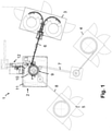
- the device 1 comprises a central area 2 in which the assembly of the cap and the connecting flange is carried out and also the making of one or more slits between a retaining ring and the lid of the cap.
- the retaining ring and cover of the closure cap are designed as a one-piece component that is fed to the central area 2 of the device 1 without a slit.
- the device 1 also includes feed sections 3, 4, 5, via which the various individual parts that are to be assembled are fed to the central region 2.
- the connecting flanges are fed in in the feed section 3
- the cutting rings are fed in in the feed section 4
- the closure caps are fed in in the feed section 5 .
- the feed sections 3 , 4 , 5 are connected to the central region 2 via feed tracks 6 , 7 , 8 .
- the cutting rings which are fed to the central region 2 via the feed section 4 and the feed track 7, are inserted into the central opening in the connecting flange, with a toothing of the cutting ring protruding from the opening in the connecting flange on the side opposite the closure cap.
- the structural unit comprising the closure cap, the connecting flange and the cutting ring, can be cut into the wall of a beverage container made of plastic or cardboard via the cutting ring.
- the central area 2 of the device 1 includes a carousel 9, in which the assembly takes place and also the slots between the retaining ring and the cover of the closure caps are made.
- the slots are created in one Slot section 10, which is located radially at a small distance from the carousel 9.
- the carousel 9 can rotate as a whole, or the central area 2 comprises a rotating ring, the axis of rotation of the carousel or rotating ring being designed as a vertical axis and in the representation according to FIG 1 perpendicular to the image plane.
- the caps mounted on the connecting flange including the cutting ring pass the slit section 10 and are scored by one or more slitting knives, so that one or more slits are created between the retaining ring and the lid of the cap.
- the central area 2 also includes a control panel 11 and an output section 12, via which the completely assembled and slotted structural units with sealing cap, connecting flange and cutting ring are output.
- the various actuators in the device are advantageously driven hydraulically, pneumatically or electrically.
- the rotary movement of the rotary ring or a carousel with the rotary ring can be carried out with the aid of an electric motor, as can the rotary movement of the carrier stamps about their longitudinal axis.
- the height adjustability of the support stamp and/or press stamp is preferably hydraulic or pneumatic.
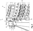
- the carousel 9 has a plurality of parallel turntables, of which the lower turntable is identified by reference number 13, the carousel 9 rotating about a central axis of rotation 14 ( 6 ), the at the same time represents a vertical axis, is rotatably mounted.
- the carousel 9 has a number of carrier stamps 15 distributed over its circumference on the outer circumference, which are each arranged to be height-adjustable and along their longitudinal axis—parallel to the axis of rotation 14 of the carousel 9—are height-adjustable.
- the height can be adjusted via drive units 16 in the floor area of the carousel 9, with the drive units 16 preferably being designed hydraulically, optionally pneumatically.
- the carrier stamps 15 each accommodate a closure cap 17, a connecting flange 18 and a cutting ring, which form a coherent structural unit when assembled.
- the connecting flange 18 has a collar, which can be provided with an external thread, onto which a cover 17a of the closure cap 17, which is provided with an internal thread, is screwed.
- a retaining ring 17b is formed integrally with the cover 17a and sits on the collar or collar below the external thread on the connecting flange 18 and advantageously sits on the connecting flange 18 in a latching position.
- the cutting ring For assembly, first the cutting ring, then the connecting flange 18 and finally the closure cap 17 are placed on the support stamp 15 .
- the connection is made by actuating the drive unit 16 and pushing the carrier stamp 15 upwards, as a result of which the components lying loosely on top of one another in the upper region of the carrier stamp 15 are pressed against a press stamp 19 fixedly arranged on the carousel.
- the closure cap 17 and the connecting flange 18 as well as the cutting ring are pressed onto one another axially.
- the height of the carrier stamp 15 is actively adjustable via the drive unit 16 , whereas the press stamp 19 is held stationary on the carousel 9 .
- a reversed embodiment is also possible with height-adjustable press dies 19 and carrier dies 15 held at a fixed height on the carousel 9.
- the assembly process takes place with a one-piece closure cap 17 with cover 17a and retaining ring 17b before the introduction of slots between the cover and retaining ring.
- a solid bond between the closure cap 17 and the connecting flange 18 including the cutting ring has been created, one or more slits are introduced between the cover 17a and the retaining ring 17b in a further step.
- the carousel 9 is rotated further about its axis of rotation 14 until the carrier stamp 15 with the closure cap 17 and connecting flange 18 and cutting ring arranged thereon reaches the area of the slot section 10 .
- the slitting section 10 is located radially outside of the carousel 9 and has two slitting knives 20a, 20b, one above the other in the vertical direction, which are curved or part-circular ( 3 , 5 ).
- the slitting knives 20a, 20b engage a portion of the cap 17 between the lid 17a and the retaining ring 17b, thereby making the desired slits in the cap 17.
- the slits extend in the circumferential direction of the closure cap 17.
- the carrier stamp 15 can perform a rotary movement about its longitudinal axis, which is parallel to the axis of rotation 14 of the carousel 9 runs. At this adjustable rotational movement, the slitting blades 20a, 20b come into contact over a desired large angular range with the peripheral side of the closure cap 17 in the section between the cover 17a and the retaining ring 17b.
- the start and end of the slit can be set via the angular velocity of the carrier stamp 15.
- the beginning and end of the slitting are also determined by the length of the slitting knives and any positioning that is offset in the circumferential direction, as well as a shorter or longer version of the slitting knives.
- the unit consisting of the closure cap 17, the connecting flange 18 and the cutting ring, can be dispensed via the dispensing section of the device.
Landscapes
- Life Sciences & Earth Sciences (AREA)
- Forests & Forestry (AREA)
- Engineering & Computer Science (AREA)
- Mechanical Engineering (AREA)
- Physics & Mathematics (AREA)
- Optics & Photonics (AREA)
- Closures For Containers (AREA)
- Making Paper Articles (AREA)
- Manufacturing Of Electrical Connectors (AREA)
Applications Claiming Priority (1)
| Application Number | Priority Date | Filing Date | Title |
|---|---|---|---|
| DE102020119383.1A DE102020119383A1 (de) | 2020-07-22 | 2020-07-22 | Vorrichtung zum Herstellen einer Verschlusskappe |
Publications (2)
| Publication Number | Publication Date |
|---|---|
| EP3943260A1 true EP3943260A1 (fr) | 2022-01-26 |
| EP3943260B1 EP3943260B1 (fr) | 2022-10-12 |
Family
ID=75904742
Family Applications (1)
| Application Number | Title | Priority Date | Filing Date |
|---|---|---|---|
| EP21020251.1A Active EP3943260B1 (fr) | 2020-07-22 | 2021-05-10 | Dispositif et procédé de fabrication d'un capuchon de fermeture |
Country Status (4)
| Country | Link |
|---|---|
| EP (1) | EP3943260B1 (fr) |
| DE (1) | DE102020119383A1 (fr) |
| ES (1) | ES2932513T3 (fr) |
| PT (1) | PT3943260T (fr) |
Cited By (2)
| Publication number | Priority date | Publication date | Assignee | Title |
|---|---|---|---|---|
| CN114905556A (zh) * | 2022-07-18 | 2022-08-16 | 利贝择(常州)软件科技有限公司 | 一种用于硅胶泥的智能自动上料机 |
| IT202200002165A1 (it) * | 2022-02-07 | 2023-08-07 | Sacmi | Apparato e metodo di taglio per capsule |
Families Citing this family (1)
| Publication number | Priority date | Publication date | Assignee | Title |
|---|---|---|---|---|
| DE102023109769B3 (de) | 2023-04-18 | 2024-09-26 | Contexo Gmbh | Vorrichtung zum Einbringen eines Schlitzes in ein Werkstück |
Citations (7)
| Publication number | Priority date | Publication date | Assignee | Title |
|---|---|---|---|---|
| EP0619168A1 (fr) | 1993-01-29 | 1994-10-12 | SACMI Cooperativa Meccanici Imola Soc. Coop. a Resp. Lim. | Dispositif pour former une ligne de fracture dans un anneau d'inviolubilité pour un bouchon à vis en matière plastique |
| EP1021282B1 (fr) | 1997-10-07 | 2004-01-07 | SACMI COOPERATIVA MECCANICI IMOLA S.c.r.l. | Dispositif permettant de constituer une ligne de rainurage dans la paroi cylindrique d'une coupelle en matiere plastique, notamment un bouchon en matiere plastique destine a fermer un contenant, et machine faisant intervenir ce dispositif |
| EP1902965A1 (fr) * | 2007-05-23 | 2008-03-26 | Ipi S.R.L. | Procédé pour l'assemblage d'un bouchon d'un conteneur et bouchon appartenant |
| DE102010048415A1 (de) * | 2010-10-15 | 2012-04-19 | Sig Technology Ag | Wiederverschließbares Ausgießelement mit Barrierefolie und Stützwand |
| EP3103603A1 (fr) * | 2015-06-08 | 2016-12-14 | Bortolin Kemo S.P.A. | Machine a découper des bouchons |
| DE102018108491A1 (de) * | 2018-04-10 | 2019-10-10 | Bericap Holding Gmbh | Fälschungssicherer Schraubverschluss |
| US20190344944A1 (en) * | 2015-04-02 | 2019-11-14 | ThisCap, Inc. | Cap for container |
-
2020
- 2020-07-22 DE DE102020119383.1A patent/DE102020119383A1/de not_active Ceased
-
2021
- 2021-05-10 ES ES21020251T patent/ES2932513T3/es active Active
- 2021-05-10 PT PT210202511T patent/PT3943260T/pt unknown
- 2021-05-10 EP EP21020251.1A patent/EP3943260B1/fr active Active
Patent Citations (7)
| Publication number | Priority date | Publication date | Assignee | Title |
|---|---|---|---|---|
| EP0619168A1 (fr) | 1993-01-29 | 1994-10-12 | SACMI Cooperativa Meccanici Imola Soc. Coop. a Resp. Lim. | Dispositif pour former une ligne de fracture dans un anneau d'inviolubilité pour un bouchon à vis en matière plastique |
| EP1021282B1 (fr) | 1997-10-07 | 2004-01-07 | SACMI COOPERATIVA MECCANICI IMOLA S.c.r.l. | Dispositif permettant de constituer une ligne de rainurage dans la paroi cylindrique d'une coupelle en matiere plastique, notamment un bouchon en matiere plastique destine a fermer un contenant, et machine faisant intervenir ce dispositif |
| EP1902965A1 (fr) * | 2007-05-23 | 2008-03-26 | Ipi S.R.L. | Procédé pour l'assemblage d'un bouchon d'un conteneur et bouchon appartenant |
| DE102010048415A1 (de) * | 2010-10-15 | 2012-04-19 | Sig Technology Ag | Wiederverschließbares Ausgießelement mit Barrierefolie und Stützwand |
| US20190344944A1 (en) * | 2015-04-02 | 2019-11-14 | ThisCap, Inc. | Cap for container |
| EP3103603A1 (fr) * | 2015-06-08 | 2016-12-14 | Bortolin Kemo S.P.A. | Machine a découper des bouchons |
| DE102018108491A1 (de) * | 2018-04-10 | 2019-10-10 | Bericap Holding Gmbh | Fälschungssicherer Schraubverschluss |
Cited By (3)
| Publication number | Priority date | Publication date | Assignee | Title |
|---|---|---|---|---|
| IT202200002165A1 (it) * | 2022-02-07 | 2023-08-07 | Sacmi | Apparato e metodo di taglio per capsule |
| CN114905556A (zh) * | 2022-07-18 | 2022-08-16 | 利贝择(常州)软件科技有限公司 | 一种用于硅胶泥的智能自动上料机 |
| CN114905556B (zh) * | 2022-07-18 | 2022-09-13 | 利贝择(常州)软件科技有限公司 | 一种用于硅胶泥的智能自动上料机 |
Also Published As
| Publication number | Publication date |
|---|---|
| EP3943260B1 (fr) | 2022-10-12 |
| ES2932513T3 (es) | 2023-01-20 |
| DE102020119383A1 (de) | 2022-01-27 |
| PT3943260T (pt) | 2022-12-06 |
Similar Documents
| Publication | Publication Date | Title |
|---|---|---|
| EP3943260B1 (fr) | Dispositif et procédé de fabrication d'un capuchon de fermeture | |
| DE69514114T2 (de) | Verfahren zum anbringen einer schwächungslinie in der wand eines behälterverschlusses | |
| EP2125542B1 (fr) | Dispositif de fermeture en plastique pourvu d'un tube coupant | |
| WO2021063776A1 (fr) | Appareil et procédé de production d'une bague de verrouillage sur un bouchon de fermeture pour un contenant | |
| DE60219109T2 (de) | Verfahren und Vorrichtung zum Thermoformen, Füllen und Verschließen von Behältern mit Hinterschnitt | |
| WO2007051328A1 (fr) | Systeme d'ouverture refermable realise a partir d'un produit semi-fini et procede pour son montage | |
| DE69214907T2 (de) | Vorrichtung und Verfahren zum Formen von Schwächungseinschnitten, insbesondere auf Behälterkappen | |
| DE60003301T2 (de) | Einheit zum Bearbeiten einer Verpackungsmaterialbahn für die Herstellung versiegelter Packungen mit fliessfähigen Nahrungsmitteln | |
| EP3400177B1 (fr) | Fermeture de récipient avec organe de perforation et bague d'inviolabilité imperdable | |
| EP0209031B1 (fr) | Boîte, ainsi que le procédé et la membrane pour sa fermeture | |
| DE2517837C2 (de) | Vorrichtung zum Verschließen eines Behälters | |
| DE202019104298U1 (de) | Verschlusskappenschneidvorrichtung | |
| DE102023109769B3 (de) | Vorrichtung zum Einbringen eines Schlitzes in ein Werkstück | |
| EP3444222B1 (fr) | Dispositif destiné à fermer une ouverture d'un récipient au moyen d'un capuchon de fermeture | |
| EP4436766A1 (fr) | Procédé et dispositif de pliage | |
| EP1568451B1 (fr) | Procédé et dispositif pour découper une matière filtrante | |
| DE3113279C2 (de) | Verfahren zur Herstellung einer Verschlusseinrichtung an einer Dose und Vorrichtung zur Ausführung des Verfahrens | |
| EP1776286B1 (fr) | Procédé d'emboutissage pour la production d'un couvercle et appareil à cet effet | |
| DE9314485U1 (de) | Vorrichtung zum Herstellen eines Kunststoff-Behälterverschlusses und Behälterverschluß | |
| EP1843893B1 (fr) | Procede et dispositif pour souder des fenetres dans des decoupes de boites pliantes | |
| AT389659B (de) | Verfahren zum herstellen eines mit einem eindrueckbaren oeffnungslappen versehenen dosendeckels aus blech | |
| DE10324012A1 (de) | Verpackungsbehälter und Verfahren zu dessen Herstellung | |
| DE4207841C2 (de) | Stopfen für einen Behälter und Verfahren zur Herstellung des Stopfens | |
| EP4563486A1 (fr) | Élément de fermeture fileté et procédé de fabrication d'un élément de fermeture | |
| EP4541552A1 (fr) | Dispositif et procédé pour plier une zone périphérique d'un bouchon pour un récépient |
Legal Events
| Date | Code | Title | Description |
|---|---|---|---|
| PUAI | Public reference made under article 153(3) epc to a published international application that has entered the european phase |
Free format text: ORIGINAL CODE: 0009012 |
|
| STAA | Information on the status of an ep patent application or granted ep patent |
Free format text: STATUS: REQUEST FOR EXAMINATION WAS MADE |
|
| 17P | Request for examination filed |
Effective date: 20211201 |
|
| AK | Designated contracting states |
Kind code of ref document: A1 Designated state(s): AL AT BE BG CH CY CZ DE DK EE ES FI FR GB GR HR HU IE IS IT LI LT LU LV MC MK MT NL NO PL PT RO RS SE SI SK SM TR |
|
| GRAP | Despatch of communication of intention to grant a patent |
Free format text: ORIGINAL CODE: EPIDOSNIGR1 |
|
| STAA | Information on the status of an ep patent application or granted ep patent |
Free format text: STATUS: GRANT OF PATENT IS INTENDED |
|
| INTG | Intention to grant announced |
Effective date: 20220302 |
|
| GRAS | Grant fee paid |
Free format text: ORIGINAL CODE: EPIDOSNIGR3 |
|
| GRAA | (expected) grant |
Free format text: ORIGINAL CODE: 0009210 |
|
| STAA | Information on the status of an ep patent application or granted ep patent |
Free format text: STATUS: THE PATENT HAS BEEN GRANTED |
|
| AK | Designated contracting states |
Kind code of ref document: B1 Designated state(s): AL AT BE BG CH CY CZ DE DK EE ES FI FR GB GR HR HU IE IS IT LI LT LU LV MC MK MT NL NO PL PT RO RS SE SI SK SM TR |
|
| REG | Reference to a national code |
Ref country code: GB Ref legal event code: FG4D Free format text: NOT ENGLISH |
|
| REG | Reference to a national code |
Ref country code: CH Ref legal event code: EP |
|
| REG | Reference to a national code |
Ref country code: DE Ref legal event code: R096 Ref document number: 502021000182 Country of ref document: DE |
|
| REG | Reference to a national code |
Ref country code: IE Ref legal event code: FG4D Free format text: LANGUAGE OF EP DOCUMENT: GERMAN |
|
| REG | Reference to a national code |
Ref country code: AT Ref legal event code: REF Ref document number: 1523882 Country of ref document: AT Kind code of ref document: T Effective date: 20221115 |
|
| REG | Reference to a national code |
Ref country code: PT Ref legal event code: SC4A Ref document number: 3943260 Country of ref document: PT Date of ref document: 20221206 Kind code of ref document: T Free format text: AVAILABILITY OF NATIONAL TRANSLATION Effective date: 20221128 |
|
| REG | Reference to a national code |
Ref country code: SE Ref legal event code: TRGR |
|
| REG | Reference to a national code |
Ref country code: ES Ref legal event code: FG2A Ref document number: 2932513 Country of ref document: ES Kind code of ref document: T3 Effective date: 20230120 |
|
| REG | Reference to a national code |
Ref country code: LT Ref legal event code: MG9D |
|
| REG | Reference to a national code |
Ref country code: NL Ref legal event code: MP Effective date: 20221012 |
|
| PG25 | Lapsed in a contracting state [announced via postgrant information from national office to epo] |
Ref country code: NL Free format text: LAPSE BECAUSE OF FAILURE TO SUBMIT A TRANSLATION OF THE DESCRIPTION OR TO PAY THE FEE WITHIN THE PRESCRIBED TIME-LIMIT Effective date: 20221012 |
|
| PG25 | Lapsed in a contracting state [announced via postgrant information from national office to epo] |
Ref country code: NO Free format text: LAPSE BECAUSE OF FAILURE TO SUBMIT A TRANSLATION OF THE DESCRIPTION OR TO PAY THE FEE WITHIN THE PRESCRIBED TIME-LIMIT Effective date: 20230112 Ref country code: LT Free format text: LAPSE BECAUSE OF FAILURE TO SUBMIT A TRANSLATION OF THE DESCRIPTION OR TO PAY THE FEE WITHIN THE PRESCRIBED TIME-LIMIT Effective date: 20221012 Ref country code: FI Free format text: LAPSE BECAUSE OF FAILURE TO SUBMIT A TRANSLATION OF THE DESCRIPTION OR TO PAY THE FEE WITHIN THE PRESCRIBED TIME-LIMIT Effective date: 20221012 |
|
| PG25 | Lapsed in a contracting state [announced via postgrant information from national office to epo] |
Ref country code: RS Free format text: LAPSE BECAUSE OF FAILURE TO SUBMIT A TRANSLATION OF THE DESCRIPTION OR TO PAY THE FEE WITHIN THE PRESCRIBED TIME-LIMIT Effective date: 20221012 Ref country code: PL Free format text: LAPSE BECAUSE OF FAILURE TO SUBMIT A TRANSLATION OF THE DESCRIPTION OR TO PAY THE FEE WITHIN THE PRESCRIBED TIME-LIMIT Effective date: 20221012 Ref country code: LV Free format text: LAPSE BECAUSE OF FAILURE TO SUBMIT A TRANSLATION OF THE DESCRIPTION OR TO PAY THE FEE WITHIN THE PRESCRIBED TIME-LIMIT Effective date: 20221012 Ref country code: IS Free format text: LAPSE BECAUSE OF FAILURE TO SUBMIT A TRANSLATION OF THE DESCRIPTION OR TO PAY THE FEE WITHIN THE PRESCRIBED TIME-LIMIT Effective date: 20230212 Ref country code: HR Free format text: LAPSE BECAUSE OF FAILURE TO SUBMIT A TRANSLATION OF THE DESCRIPTION OR TO PAY THE FEE WITHIN THE PRESCRIBED TIME-LIMIT Effective date: 20221012 Ref country code: GR Free format text: LAPSE BECAUSE OF FAILURE TO SUBMIT A TRANSLATION OF THE DESCRIPTION OR TO PAY THE FEE WITHIN THE PRESCRIBED TIME-LIMIT Effective date: 20230113 |
|
| REG | Reference to a national code |
Ref country code: DE Ref legal event code: R097 Ref document number: 502021000182 Country of ref document: DE |
|
| PG25 | Lapsed in a contracting state [announced via postgrant information from national office to epo] |
Ref country code: SM Free format text: LAPSE BECAUSE OF FAILURE TO SUBMIT A TRANSLATION OF THE DESCRIPTION OR TO PAY THE FEE WITHIN THE PRESCRIBED TIME-LIMIT Effective date: 20221012 Ref country code: RO Free format text: LAPSE BECAUSE OF FAILURE TO SUBMIT A TRANSLATION OF THE DESCRIPTION OR TO PAY THE FEE WITHIN THE PRESCRIBED TIME-LIMIT Effective date: 20221012 Ref country code: EE Free format text: LAPSE BECAUSE OF FAILURE TO SUBMIT A TRANSLATION OF THE DESCRIPTION OR TO PAY THE FEE WITHIN THE PRESCRIBED TIME-LIMIT Effective date: 20221012 Ref country code: DK Free format text: LAPSE BECAUSE OF FAILURE TO SUBMIT A TRANSLATION OF THE DESCRIPTION OR TO PAY THE FEE WITHIN THE PRESCRIBED TIME-LIMIT Effective date: 20221012 Ref country code: CZ Free format text: LAPSE BECAUSE OF FAILURE TO SUBMIT A TRANSLATION OF THE DESCRIPTION OR TO PAY THE FEE WITHIN THE PRESCRIBED TIME-LIMIT Effective date: 20221012 |
|
| PLBE | No opposition filed within time limit |
Free format text: ORIGINAL CODE: 0009261 |
|
| STAA | Information on the status of an ep patent application or granted ep patent |
Free format text: STATUS: NO OPPOSITION FILED WITHIN TIME LIMIT |
|
| PG25 | Lapsed in a contracting state [announced via postgrant information from national office to epo] |
Ref country code: SK Free format text: LAPSE BECAUSE OF FAILURE TO SUBMIT A TRANSLATION OF THE DESCRIPTION OR TO PAY THE FEE WITHIN THE PRESCRIBED TIME-LIMIT Effective date: 20221012 Ref country code: AL Free format text: LAPSE BECAUSE OF FAILURE TO SUBMIT A TRANSLATION OF THE DESCRIPTION OR TO PAY THE FEE WITHIN THE PRESCRIBED TIME-LIMIT Effective date: 20221012 |
|
| 26N | No opposition filed |
Effective date: 20230713 |
|
| PG25 | Lapsed in a contracting state [announced via postgrant information from national office to epo] |
Ref country code: SI Free format text: LAPSE BECAUSE OF FAILURE TO SUBMIT A TRANSLATION OF THE DESCRIPTION OR TO PAY THE FEE WITHIN THE PRESCRIBED TIME-LIMIT Effective date: 20221012 |
|
| PG25 | Lapsed in a contracting state [announced via postgrant information from national office to epo] |
Ref country code: MC Free format text: LAPSE BECAUSE OF FAILURE TO SUBMIT A TRANSLATION OF THE DESCRIPTION OR TO PAY THE FEE WITHIN THE PRESCRIBED TIME-LIMIT Effective date: 20221012 |
|
| PG25 | Lapsed in a contracting state [announced via postgrant information from national office to epo] |
Ref country code: MC Free format text: LAPSE BECAUSE OF FAILURE TO SUBMIT A TRANSLATION OF THE DESCRIPTION OR TO PAY THE FEE WITHIN THE PRESCRIBED TIME-LIMIT Effective date: 20221012 Ref country code: LU Free format text: LAPSE BECAUSE OF NON-PAYMENT OF DUE FEES Effective date: 20230510 |
|
| PG25 | Lapsed in a contracting state [announced via postgrant information from national office to epo] |
Ref country code: BG Free format text: LAPSE BECAUSE OF FAILURE TO SUBMIT A TRANSLATION OF THE DESCRIPTION OR TO PAY THE FEE WITHIN THE PRESCRIBED TIME-LIMIT Effective date: 20221012 |
|
| PG25 | Lapsed in a contracting state [announced via postgrant information from national office to epo] |
Ref country code: BG Free format text: LAPSE BECAUSE OF FAILURE TO SUBMIT A TRANSLATION OF THE DESCRIPTION OR TO PAY THE FEE WITHIN THE PRESCRIBED TIME-LIMIT Effective date: 20221012 |
|
| PGFP | Annual fee paid to national office [announced via postgrant information from national office to epo] |
Ref country code: DE Payment date: 20250602 Year of fee payment: 5 |
|
| PGFP | Annual fee paid to national office [announced via postgrant information from national office to epo] |
Ref country code: GB Payment date: 20250524 Year of fee payment: 5 Ref country code: ES Payment date: 20250602 Year of fee payment: 5 |
|
| PGFP | Annual fee paid to national office [announced via postgrant information from national office to epo] |
Ref country code: BE Payment date: 20250520 Year of fee payment: 5 Ref country code: IT Payment date: 20250529 Year of fee payment: 5 |
|
| PGFP | Annual fee paid to national office [announced via postgrant information from national office to epo] |
Ref country code: PT Payment date: 20250502 Year of fee payment: 5 |
|
| PGFP | Annual fee paid to national office [announced via postgrant information from national office to epo] |
Ref country code: FR Payment date: 20250520 Year of fee payment: 5 |
|
| PGFP | Annual fee paid to national office [announced via postgrant information from national office to epo] |
Ref country code: CH Payment date: 20250601 Year of fee payment: 5 |
|
| PGFP | Annual fee paid to national office [announced via postgrant information from national office to epo] |
Ref country code: AT Payment date: 20250721 Year of fee payment: 5 |
|
| PG25 | Lapsed in a contracting state [announced via postgrant information from national office to epo] |
Ref country code: CY Free format text: LAPSE BECAUSE OF FAILURE TO SUBMIT A TRANSLATION OF THE DESCRIPTION OR TO PAY THE FEE WITHIN THE PRESCRIBED TIME-LIMIT; INVALID AB INITIO Effective date: 20210510 |
|
| PGFP | Annual fee paid to national office [announced via postgrant information from national office to epo] |
Ref country code: TR Payment date: 20250505 Year of fee payment: 5 |
|
| PGFP | Annual fee paid to national office [announced via postgrant information from national office to epo] |
Ref country code: IE Payment date: 20250521 Year of fee payment: 5 |
|
| PGFP | Annual fee paid to national office [announced via postgrant information from national office to epo] |
Ref country code: SE Payment date: 20250524 Year of fee payment: 5 |
|
| PG25 | Lapsed in a contracting state [announced via postgrant information from national office to epo] |
Ref country code: HU Free format text: LAPSE BECAUSE OF FAILURE TO SUBMIT A TRANSLATION OF THE DESCRIPTION OR TO PAY THE FEE WITHIN THE PRESCRIBED TIME-LIMIT; INVALID AB INITIO Effective date: 20210510 |