EP3943306B1 - Système d'impression - Google Patents
Système d'impression Download PDFInfo
- Publication number
- EP3943306B1 EP3943306B1 EP20777299.7A EP20777299A EP3943306B1 EP 3943306 B1 EP3943306 B1 EP 3943306B1 EP 20777299 A EP20777299 A EP 20777299A EP 3943306 B1 EP3943306 B1 EP 3943306B1
- Authority
- EP
- European Patent Office
- Prior art keywords
- moving
- moving route
- route
- exemplary embodiment
- linear
- Prior art date
- Legal status (The legal status is an assumption and is not a legal conclusion. Google has not performed a legal analysis and makes no representation as to the accuracy of the status listed.)
- Active
Links
Images



Classifications
-
- B—PERFORMING OPERATIONS; TRANSPORTING
- B41—PRINTING; LINING MACHINES; TYPEWRITERS; STAMPS
- B41J—TYPEWRITERS; SELECTIVE PRINTING MECHANISMS, i.e. MECHANISMS PRINTING OTHERWISE THAN FROM A FORME; CORRECTION OF TYPOGRAPHICAL ERRORS
- B41J3/00—Typewriters or selective printing or marking mechanisms characterised by the purpose for which they are constructed
- B41J3/407—Typewriters or selective printing or marking mechanisms characterised by the purpose for which they are constructed for marking on special material
- B41J3/4073—Printing on three-dimensional objects not being in sheet or web form, e.g. spherical or cubic objects
- B41J3/40733—Printing on cylindrical or rotationally symmetrical objects, e. g. on bottles
-
- B—PERFORMING OPERATIONS; TRANSPORTING
- B41—PRINTING; LINING MACHINES; TYPEWRITERS; STAMPS
- B41F—PRINTING MACHINES OR PRESSES
- B41F17/00—Printing apparatus or machines of special types or for particular purposes, not otherwise provided for
- B41F17/08—Printing apparatus or machines of special types or for particular purposes, not otherwise provided for for printing on filamentary or elongated articles, or on articles with cylindrical surfaces
- B41F17/14—Printing apparatus or machines of special types or for particular purposes, not otherwise provided for for printing on filamentary or elongated articles, or on articles with cylindrical surfaces on articles of finite length
- B41F17/20—Printing apparatus or machines of special types or for particular purposes, not otherwise provided for for printing on filamentary or elongated articles, or on articles with cylindrical surfaces on articles of finite length on articles of uniform cross-section, e.g. pencils, rulers, resistors
- B41F17/22—Printing apparatus or machines of special types or for particular purposes, not otherwise provided for for printing on filamentary or elongated articles, or on articles with cylindrical surfaces on articles of finite length on articles of uniform cross-section, e.g. pencils, rulers, resistors by rolling contact
-
- B—PERFORMING OPERATIONS; TRANSPORTING
- B41—PRINTING; LINING MACHINES; TYPEWRITERS; STAMPS
- B41J—TYPEWRITERS; SELECTIVE PRINTING MECHANISMS, i.e. MECHANISMS PRINTING OTHERWISE THAN FROM A FORME; CORRECTION OF TYPOGRAPHICAL ERRORS
- B41J11/00—Devices or arrangements of selective printing mechanisms, e.g. ink-jet printers or thermal printers, for supporting or handling copy material in sheet or web form
- B41J11/0045—Guides for printing material
-
- B—PERFORMING OPERATIONS; TRANSPORTING
- B41—PRINTING; LINING MACHINES; TYPEWRITERS; STAMPS
- B41J—TYPEWRITERS; SELECTIVE PRINTING MECHANISMS, i.e. MECHANISMS PRINTING OTHERWISE THAN FROM A FORME; CORRECTION OF TYPOGRAPHICAL ERRORS
- B41J25/00—Actions or mechanisms not otherwise provided for
- B41J25/001—Mechanisms for bodily moving print heads or carriages parallel to the paper surface
-
- B—PERFORMING OPERATIONS; TRANSPORTING
- B41—PRINTING; LINING MACHINES; TYPEWRITERS; STAMPS
- B41J—TYPEWRITERS; SELECTIVE PRINTING MECHANISMS, i.e. MECHANISMS PRINTING OTHERWISE THAN FROM A FORME; CORRECTION OF TYPOGRAPHICAL ERRORS
- B41J11/00—Devices or arrangements of selective printing mechanisms, e.g. ink-jet printers or thermal printers, for supporting or handling copy material in sheet or web form
- B41J11/0015—Devices or arrangements of selective printing mechanisms, e.g. ink-jet printers or thermal printers, for supporting or handling copy material in sheet or web form for treating before, during or after printing or for uniform coating or laminating the copy material before or after printing
- B41J11/002—Curing or drying the ink on the copy materials, e.g. by heating or irradiating
- B41J11/0021—Curing or drying the ink on the copy materials, e.g. by heating or irradiating using irradiation
- B41J11/00214—Curing or drying the ink on the copy materials, e.g. by heating or irradiating using irradiation using UV radiation
Definitions
- the present invention relates to a print system.
- Patent Document 1 there is disclosed a printing device including a mandrel wheel, plural automatically-rotatable mandrels provided to the mandrel wheel, and an inkjet printing station for forming a print image at least on the body part of the outer surface of the seamless can mounted on the mandrel by inkjet printing.
- US 2016/136968 A1 discloses a print system comprising a moving body supporting a can body, an upper moving route, a lower moving route and an image forming unit performing image formation onto the can body supported by the moving body.
- Patent Document 1 Japanese Patent Application Laid-Open Publication No. 2012-232771
- Provision of an upper moving route, which is a moving route on an upper side, and a lower moving route, which is a moving route on a lower side, that are taken by a moving body supporting a can body makes it possible to perform processing on the can body at plural locations in the height direction.
- An object of the present invention is to make positional relation between an upper moving route, which a moving body moving while supporting a can body travels, and a processing unit performing processing on the can body, and positional relation between a lower moving route, which a moving body moving while supporting a can body travels, and a processing unit performing processing on the can body differ from each other.
- a print system to which the present invention is applied is disclosed in claim 1.
- the print system may further include a guidance part provided along the annular moving route and guiding the moving body, wherein the moving body may include a guided part to be guided by the guidance part and a can body support part to be inserted into the can body to support the can body, the can body support part may be positioned above the guided part while the moving body is located on the upper moving route, and the can body support part may be positioned below the guided part while the moving body is located on the lower moving route.
- the upper moving route and the lower moving route may be disposed in parallel with each other.
- the upper moving route and the lower moving route may overlap each other.
- the annular moving route may be disposed on a plane extending along a vertical direction.
- FIG. 1 is a side elevational view of a print system 500.
- the print system 500 is provided with a can body supply part 510 to which can bodies 10 are supplied.
- the can body 10 is supplied (attached) to a support member 20 supporting the can body 10.
- the support member 20 is formed into a cylindrical shape and the support member 20 is inserted into the cylindrically-shaped can body 10; thereby the can body 10 is supplied to the support member 20.
- the print system 500 is provided with plural moving units 550 as an example of moving bodies that move while supporting the can bodies 10.
- a support member 20, as an example of a can body support part supporting the can body 10, is attached to the moving unit 550.
- the can body 10 is supported by the support member 20 and moves with the moving unit 550.
- FIG. 1 shows a case in which the moving unit 550 supports a single can body 10; however, as will be described later, plural can bodies 10 may be placed on the moving unit 550, and thereby the single moving unit 550 may support the plural can bodies 10.
- the support member 20 is formed into a cylindrical shape and further, the support member 20 is provided rotatable state in the circumferential direction.
- the can body 10 is supported by the support member 20 that is rotatable in the circumferential direction, and thereby the can body 10 is supported in the state being rotatable in the circumferential direction.
- the can body 10 is formed into a cylindrical shape and an opening portion is provided at one end thereof. Moreover, the other end of the can body 10 is closed and the other end is provided with a bottom portion 10A.
- the support member 20 is inserted into the can body 10 from the opening portion.
- a moving mechanism 560 that functions as a mover unit that moves the moving units 550 is provided.
- the moving mechanism 560 is provided with an annular-shaped guidance member 561 that guides the moving units 550.
- Each of the moving units 550 is guided by the guidance member 561 and orbitally moves along an annular moving route 732, which is a predetermined annular-shaped moving route.
- the support member 20 provided to the moving unit 550 also moves along the annular moving route 732.
- the guidance member 561 that functions as a guidance part is provided along the annular moving route 732, to thereby guide the moving unit 550 moving along the annular moving route 732.
- the can body 10 supported by the support member 20 moves along a predetermined annular-shaped can body moving route 800.
- the annular moving route 732 (the same is true for the can body moving route 800) is disposed so that the axial center 800C thereof is arranged along the horizontal direction.
- the can body moving route 800 is disposed around the axial center 800C along the horizontal direction.
- the axial center 800C extends in the direction perpendicular to the page in FIG. 1 .
- the annular moving route 732 is disposed on a plane extending along the vertical direction. To put it another way, the annular moving route 732 is disposed on a plane extending along the page of FIG. 1 .
- the support member 20 and the can body 10 orbitally move around the axial center 800C extending in the direction perpendicular to the page in the figure.
- the annular moving route 732 is provided with a first linear moving route 910 formed linearly from the upper side to the lower side, and a second linear moving route 920 formed linearly from the lower side to the upper side.
- first linear moving route 910 and the second linear moving route 920 are disposed along the vertical direction.
- first linear moving route 910 and the second linear moving route 920 are disposed in parallel with each other.
- the exemplary embodiment is provided with both of the first linear moving route 910 and the second linear moving route 920, but either one of them may be provided.
- first linear moving route 910 and the second linear moving route 920 are disposed along the vertical direction; however, the first linear moving route 910 and the second linear moving route 920 may be provided in the state of being inclined to the vertical direction.
- the full lengths of the first linear moving route 910 and the second linear moving route 920 are equal.
- projection from the first linear moving route 910 side toward the second linear moving route 920 side in the horizontal direction makes the first linear moving route 910 and the second linear moving route 920 overlap each other.
- projection of the first linear moving route 910 and the second linear moving route 920 in the horizontal direction and the direction perpendicular to the direction in which the axial center 800C extends makes the first linear moving route 910 and the second linear moving route 920 overlap each other.
- the annular moving route 732 is provided with a lateral moving route that is a moving route extending along the lateral direction (horizontal direction).
- the lateral moving route is provided as a moving route constituting a part of the annular moving route 732.
- an upper moving route 930 and a lower moving route 940 are provided as the lateral moving route.
- the upper moving route 930 and the lower moving route 940 are provided to be displaced from each other in the up-and-down direction. Further, the upper moving route 930 and the lower moving route 940 extend along the lateral direction (horizontal direction, the direction intersecting the vertical direction) and are formed linearly.
- the full lengths of the upper moving route 930 and the lower moving route 940 are equal.
- the upper moving route 930 and the lower moving route 940 are disposed in parallel with each other.
- the upper moving route 930 is positioned directly above the lower moving route 940, and projection of the upper moving route 930 and the lower moving route 940 downward in the vertical direction makes the upper moving route 930 and the lower moving route 940 overlap each other.
- the upper moving route 930 is provided to the uppermost portion of the annular moving route 732, whereas the lower moving route 940 is provided to the lowermost portion of the annular moving route 732.
- the moving unit 550 moves in the right direction in the figure, whereas, in the lower moving route 940, the moving unit 550 moves in the left direction in the figure.
- the moving unit 550 moves in one direction, and in the lower moving route 940, the moving unit 550 moves in an opposite direction of the one direction.
- annular moving route 732 is provided with a first connecting route 950 that connects the upper moving route 930 and the first linear moving route 910 and a second connecting route 960 that connects the first linear moving route 910 and the lower moving route 940.
- the annular moving route 732 is also provided with a third connecting route 970 that connects the lower moving route 940 and the second linear moving route 920 and a fourth connecting route 980 that connects the second linear moving route 920 and the upper moving route 930.
- Any of the first connecting route 950 to the fourth connecting route 980 has a curvature and is formed to draw an arc of 1/4 of the circumference.
- first connecting route 950 and the second connecting route 960 are formed to go downward as the moving unit 550 moves to the downstream side in the moving direction.
- third connecting route 970 and the fourth connecting route 980 are formed to go upward as the moving unit 550 moves to the downstream side in the moving direction.
- the moving unit 550 moves along the first connecting route 950, the first linear moving route 910, and the second connecting route 960, the moving unit 550 moves downward.
- the moving unit 550 moves along the third connecting route 970, the second linear moving route 920, and the fourth connecting route 980, the moving unit 550 moves upward.
- the exemplary embodiment is provided with a first inspection device 92.
- the first inspection device 92 carries out inspection of the can body 10, which is an example of processing for the can body 10 supported by the moving unit 550 positioned on the second linear moving route 920.
- the first inspection device 92 inspects whether or not the can body 10 is deformed.
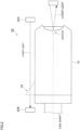
- the first inspection device 92 is provided with, as shown in FIG. 2 (the diagram illustrating the first inspection device 92), a light source 92A.
- the light source 92A is provided on one end portion side of the can body 10 and the light source 92A emits laser light that proceeds in an axial direction of the can body 10 along the outer circumferential surface of the can body 10. Further, on the other end portion side of the can body 10, a light receiving portion 92B that receives laser light from the light source 92A is provided.
- a first discharge mechanism 93 discharges the can body 10 to the outside of the print system 500.
- the first discharge mechanism 93 is provided on the lateral side of the fourth connecting route 980 (on the lateral side and outside of the annular moving route 732), and, when the moving unit 550 is positioned on the fourth connecting route 980, the first discharge mechanism 93 discharges the can body 10 supported by the moving unit 550.
- first discharge mechanism 93 compressed air is supplied to the inside of the cylindrically-formed support member 20, to move the can body 10 in the axial direction thereof (in the direction perpendicular to the page of FIG. 1 ).
- the bottom portion 10A (the closed end portion) of the can body 10 is sucked by a not-shown suction member. Then, by the suction member, the can body 10 is conveyed to the outside of the print system 500; thereby the can body 10 is discharged to the outside of the print system 500.
- an inkjet printing part 700 is provided on the downstream side of the first discharge mechanism 93.
- the inkjet printing part 700 forms an image onto an outer surface 10X of the can body 10 moved from the upstream side by use of the inkjet printing method.
- the inkjet printing part 700 performs image formation onto the can body 10 supported by the moving unit 550.
- the moving units 550 sequentially move from the upstream side of the inkjet printing part 700 toward the inkjet printing part 700 (refer to the arrow 1A).
- image formation by the inkjet printing part 700 is performed onto the can bodies 10 on the moving units 550.
- the image formation by the inkjet printing method refers to image formation performed by ejecting ink from inkjet heads 11 to attach the ink to the can body 10.
- a piezo system In the image formation by the inkjet printing method, known methods can be used. Specifically, for example, a piezo system, a thermal (bubble) system, a continuous system or the like can be used.
- a light irradiation part 750 is provided as an example of a curing unit.
- the light irradiation part 750 includes a light source (not shown) and irradiates the outer surface 10X of the can body 10, on which image formation by the inkjet printing part 700 has been performed, with light, to thereby cure the image formed on the outer surface 10X.
- the image is formed by use of ultraviolet cure ink.
- the image is formed by use of actinic radiation cure ink.
- the formed image is irradiated with light, such as ultraviolet light. This cures the image formed on the outer surface 10X of the can body 10.
- a second inspection device 300 On the downstream side of the light irradiation part 750, a second inspection device 300, as an example of an inspection unit, that carries out inspection of the image formed by the inkjet printing part 700 on the outer surface 10X of the can body 10 is provided.
- the second inspection device 300 carries out inspection of the can body 10, which is an example of processing for the can body 10 supported by the moving unit 550 positioned on the first linear moving route 910.
- both lateral sides of the first linear moving route 910 and the second linear moving route 920, the inspection devices (the first inspection device 92 and the second inspection device 300) carrying out the inspection of the can bodies 10 are provided.
- the processing units that carry out processing on the can bodies 10 are provided on both lateral sides of the first linear moving route 910 and the second linear moving route 920.
- the full length of the upper moving route 930 is increased, and, with this, the size of the print system 500 in the direction indicated by the reference sign 1E is also increased. Then, in this case, the occupation area of the print system 500 is increased.
- the second inspection device 300 is provided on the upstream side of a protection layer forming part 770 (to be described later) in the moving direction of the can body 10, and, in the exemplary embodiment, inspection of the image formed on the can body 10 is performed before application of paint onto the can body 10 by the protection layer forming part 770.
- the inkjet printing part 700 and the light irradiation part 750 are provided on the lateral side of the upper moving route 930.
- a second discharge mechanism 400 as an example of the discharge unit, that discharges the can body 10 positioned on the can body moving route 800 from the print system 500 (the can body moving route 800) is provided.
- the second discharge mechanism 400 discharges the can body 10, the result of inspection of which performed by the second discharge mechanism 300 satisfies predetermined conditions, from the print system 500. To put it another way, the second discharge mechanism 400 discharges the so-called defective can, in which the image formed thereon includes defects, from the print system 500.
- the second inspection device 300 is provided on the lateral side of the first linear moving route 910
- the second discharge mechanism 400 is provided on the lateral side of the lower moving route 940
- the second connecting route 960 is provided between the second inspection device 300 and the second discharge mechanism 400.
- the second discharge mechanism 400 similar to the first discharge mechanism 93, compressed air is supplied to the inside of the cylindrically-formed support member 20, to move the can body 10 in the axial direction thereof (in the direction perpendicular to the page of FIG. 1 ).
- the bottom portion 10A (the closed end portion) of the can body 10 is sucked by a not-shown suction member. Then, by the suction member, the can body 10 is conveyed to the outside of the print system 500; thereby the can body 10 is discharged to the outside of the print system 500.
- the can body 10 is conveyed to the outside of the can body moving route 800 to be discharged.
- the protection layer forming part 770 is provided on the downstream side of the second discharge mechanism 400.
- the protection layer forming part 770 applies transparent paint onto the outer surface 10X of the can body 10.
- the protection layer forming part 770 brings a roll-shaped member 701 with the paint on the outer circumferential surface thereof into contact with the outer surface 10X of the can body 10, to thereby apply the transparent paint to the outer surface 10X.
- the protection layer forming part 770 applies the transparent paint on the image formed by the inkjet printing part 700 to form a transparent layer covering the image. Consequently, a transparent protection layer is formed as the outermost layer of the can body 10.
- a detachment part 780 (can body discharge part) detaching the can body 10 from the support member 20 is provided.
- the can body 10 is detached from the support member 20 in the detachment part 780 to be discharged to the outside of the print system 500.
- the second discharge mechanism 400, the protection layer forming part 770, the detachment part 780, and the can body supply part 510 performing processing on the can body 10 are provided on the lateral side (lower side) of the lower moving route 940.
- the plural processing units performing processing on the can bodies 10 are provided below the lower moving route 940 to be arranged in line along the extending direction of the lower moving route 940.
- the inkjet printing part 700 and the light irradiation part 750 performing processing on the can body 10 are provided.
- the plural processing units performing processing on the can bodies 10 are provided above the upper moving route 930 to be arranged in line along the extending direction of the upper moving route 930.
- the processing units performing processing on the can body 10 are provided on both lateral sides of the upper moving route 930 and the lower moving route 940.
- the second inspection device 300 is provided on the upstream side of the protection layer forming part 770 to perform inspection of the image before the paint is applied onto the can body 10 by the protection layer forming part 770, the image defects are more likely to be detected.
- image formation onto the can body 10 is performed by use of the inkjet heads 11; however, the image formation onto the can body 10 may be performed by use of the plate printing method, such as relief printing.
- the inkjet printing part 700 shown in FIG. 1 is disposed above (on the lateral side of) the upper moving route 930 to perform image formation onto the can body 10 supported by the moving unit 550 positioned on the upper moving route 930.
- the inkjet printing part 700 is provided with plural inkjet heads 11 arranged in line in the left and right directions in the figure.
- the portion where the plural inkjet heads 11 are provided can be grasped as an image forming unit that performs image formation onto the can body 10.
- the inkjet printing part 700 is provided with a first inkjet head 11C ejecting cyan ink, a second inkjet head 11M ejecting magenta ink, a third inkjet head 11Y ejecting yellow ink and a fourth inkjet head 11K ejecting black ink.
- inkjet heads 11 when the first inkjet head 11C to the fourth inkjet head 11K are not particularly distinguished, the inkjet heads are simply referred to as “inkjet heads 11.”
- the four inkjet heads 11, namely, the first inkjet head 11C to the fourth inkjet head 11K perform image formation onto the can body 10 by use of the ultraviolet cure ink.
- the can body 10 is moved in a state of being laid (the can body 10 is moved in the state in which the axial direction of the can body 10 extends along the horizontal state), and a part of the outer surface 10X of the can body 10 faces upward in the vertical direction.
- ink is ejected downwardly from above the outer surface 10X, to thereby perform image formation onto the outer surface 10X of the can body 10.
- the moving unit 550 stops under each of the inkjet heads 11 and the ink is ejected to the can body 10 on the moving unit 550, and thereby the image formation onto the can body 10 is performed.
- the moving unit 550 moves to the next inkjet head 11 positioned on the downstream side, and the image formation onto the can body 10 is also performed by the inkjet head 11.
- the four inkjet heads 11 are arranged in line along the moving direction of the can body 10. Moreover, each of the four inkjet heads 11 is disposed along a direction perpendicular to (crossing) the moving direction of the can body 10.
- ink is ejected to the can body 10 from above, and thereby an image is formed on the can body 10.
- the moving unit 550 stops at the installation location of each of the plural inkjet heads 11 that have been provided.
- Each of the moving units 550 moves at a predetermined moving speed.
- each of the moving units 550 stops at each of the can body supply part 510, the first inspection device 92, the first discharge mechanism 93, each of the inkjet heads 11, the light irradiation part 750, the second inspection device 300, the second discharge mechanism 400, the protection layer forming part 770 and the detachment part 780.
- the can body 10 on the moving unit 550 rotates in the circumferential direction at the predetermined rotation speed.
- the moving units 550 are installed. Further, the moving units 550 move around the axial center 800C.
- the moving mechanism 560 is provided with an annular-shaped guidance member 561 that guides the moving units 550. Inside the guidance member 561, electromagnets (not shown) are provided.
- a permanent magnet (not shown) is installed.
- a linear motor mechanism is used to move the moving units 550.
- the print system 500 of the exemplary embodiment is provided with a control part 900 that controls energization to the above-described electromagnets to generate magnetic fields for moving each of the moving units 550.
- the control part 900 is composed of a program-controlled CPU (Central Processing Unit).
- the moving unit 550 is provided with a pedestal part 551, as an example of a guided part guided by the guidance member 561.
- the pedestal part 551 contacts the guidance member 561, and the moving direction thereof is determined by the guidance member 561.
- a permanent magnet (not shown) is installed in the pedestal part 551.
- a propulsive force occurs in the moving unit 550 by magnetic fields generated by electromagnets provided to the guidance member 561 and the permanent magnet provided to the pedestal part 551 of the moving unit 550, and thereby the moving unit 550 moves along the annular moving route 732.
- the moving unit 550 of the exemplary embodiment is provided with the cylindrical support member 20 supporting the can body 10 and a fixing member (not shown) for fixing the support member 20 to the pedestal part 551.
- the support member 20 is formed into the cylindrical shape, and inserted into the can body 10 through the opening portion formed in the can body 10 to support the can body 10.
- the support member 20 is disposed in the state of being laid (along the horizontal direction). Consequently, in the exemplary embodiment, the can body 10 is also disposed in the state of being laid.
- the light irradiation part 750 is disposed on the downstream side of the inkjet printing part 700 and irradiates the can body 10 with the ultraviolet light being an example of light. Consequently, the image formed on the outer surface (outer circumferential surface) 10X of the can body 10 (the image formed by the inkjet printing part 700) is cured.
- thermosetting ink may also be used; in this case, for example, a heat source, not a light source, is installed at the location where the light irradiation part 750 is provided.
- the moving unit 550 stops every time the moving unit 550 reaches below each of the inkjet heads 11. In other words, the moving unit 550 stops at each of predetermined stop locations.
- an image is formed by the inkjet heads 11 as an example of the image forming unit.
- ejection of ink from the inkjet head 11 is performed in the state in which the support member 20 (the can body 10) rotates in the circumferential direction, to thereby form an image onto the outer surface 10X of the can body 10.
- the support member 20 shown in FIG. 1 is disposed along the direction perpendicular to the page of FIG. 1 . To put it another way, the support member 20 is disposed to extend along the horizontal direction.
- the support member 20 is disposed along the direction perpendicular to (crossing) the moving direction of the moving unit 550.
- the inkjet heads 11 are positioned above the can body 10, and the ink is ejected to the can body 10 from above.
- the inkjet printing part 700 (the plural inkjet heads 11) is provided on the lateral side of (above) the upper moving route 930 (horizontal moving route).
- the inkjet printing part 700 (the plural inkjet heads 11) is provided on the lateral side of the curved part (the route having the curvature as, for example, the first connecting route 950 to the fourth connecting route 980), quality of the image to be formed on the can body 10 is likely to be improved.
- the attitudes of the inkjet heads 11 are different in each of the inkjet heads 11.
- the quality of the image to be formed is likely to be degraded due to occurrence of misregistration among images formed by the respective inkjet heads 11.
- the inkjet printing part 700 is provided on the lateral side of the linear part (the upper moving route 930 (horizontal moving route)) as in the exemplary embodiment, the attitudes of the plural inkjet heads 11 are easily aligned, and thereby degradation of quality of the image to be formed can be suppressed.
- the exemplary embodiment has the configuration in which the inkjet printing part 700, which is the image forming unit, performs image formation onto the can body 10 when the moving unit 550 is positioned on the horizontal moving route; in this case, degradation of quality of the image to be formed is suppressed with ease.
- the description was given by taking the case in which the inkjet printing part 700 is provided on the lateral side of the upper moving route 930 as an example; however, it does not mean to exclude the possibility of providing the inkjet printing part 700 on the lateral side of the lower moving route 940.
- the inkjet printing part 700 is provided on the lateral side of the lower moving route 940, in a similar way, the attitudes of the plural inkjet heads 11 are easily aligned, and thereby degradation of quality of the image to be formed can be suppressed.
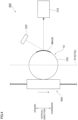
- FIG. 4 is a diagram illustrating the second inspection device 300.
- the second inspection device 300 of the exemplary embodiment is provided with a photographing device 310, as an example of a photographing unit that takes a photograph of the image formed on the outer surface 10X of the can body 10.
- the photographing device 310 is configured to include a photographing element, such as a CCD (Charge Coupled Device). Further, the second inspection device 300 is provided with a light source 320 emitting light with which the can body 10 is irradiated.
- a photographing element such as a CCD (Charge Coupled Device).
- the second inspection device 300 is provided with a light source 320 emitting light with which the can body 10 is irradiated.
- the second inspection device 300 analyzes the image obtained by the photographing device 310, and thereby performs inspection of the image formed on the outer surface 10X of the can body 10.
- the second inspection device 300 compares, for example, the image obtained by the photographing device 310 and a reference image registered in advance; thereby the inspection to determine whether or not the image formed on the outer surface 10X of the can body 10 has defects is carried out.
- the moving unit 550 when the moving unit 550 is positioned on the first linear moving route 910 that is linearly formed, the image formed on the outer surface 10X of the can body 10 on the moving unit 550 is photographed by use of the photographing device 310.
- inspection of the image formed on the outer surface 10X of the can body 10 is performed by the second inspection device 300.
- accuracy of inspection of the image on the can body 10 can be increased, as compared to the case in which the inspection of the can body 10 (photo shooting of the can body 10) is performed when the can body 10 is positioned on the first connecting route 950 or the like having the curvature.
- the accuracy of the stop position of the moving unit 550 is likely to be degraded.
- the position of the can body 10 in photographing the can body 10 by using the photographing device 310 is liable to vary, and the inspection accuracy of the image is likely to be degraded due to the variation.
- the second discharge mechanism 400 as an example of the discharge unit, is provided on the upstream side of the protection layer forming part 770, as an example of the paint application unit.
- the defective can is discharged from the print system 500 before the paint is applied.
- the amount of paint to be used can be reduced, as compared to the case in which even the defective can is subjected to application of the paint.
- the second inspection device 300 performs inspection of the image after being cured by the light irradiation part 750 and before application of the paint.
- the second inspection device 300 is provided on the downstream side of the light irradiation part 750 and on the upstream side of the protection layer forming part 770, to thereby perform inspection of the image that is cured by the light irradiation part 750 prior to application of the paint on the surface thereof.
- the inspection of the image is performed before the image is cured, there is a risk that a change occurs in the image after the inspection and the state of the image is changed. Moreover, if the inspection of the image is performed after the paint is applied onto the surface of the image, the image defects generated in forming the image become less noticeable, and thereby the defects are less likely to be detected, as described above.
- the first linear moving route 910 and the second linear moving route 920 are disposed along the up-and-down direction; accordingly, in the exemplary embodiment, compatibility between improvement in processing accuracy for the can body 10 and reduction of the occupation area of the print system 500 is sought after.
- the processing on the can body 10 is to be performed when the moving unit 550 is positioned on a linear-shaped moving route, such as the first linear moving route 910 or the second linear moving route 920, degradation of processing accuracy arising from the positional accuracy of the moving unit 550 can be suppressed, as compared to the case in which the processing on the can body 10 is to be performed when the moving unit 550 is positioned on the moving route having a curvature.
- the processing on the can body 10 is performed when the moving unit 550 is positioned on the linear-shaped moving route.
- the upper moving route 930 and the lower moving route 940 are also provided as the linear-shaped moving route; therefore, it is possible to consider a mode in which the first inspection device 92 and the second inspection device 300 are provided on the lateral sides of the upper moving route 930 and the lower moving route 940.
- the size of the print system 500 in the direction indicated by the reference sign 1E is increased, and accordingly, the occupation area of the print system 500 tends to be increased.
- first inspection device 92 and the second inspection device 300 are provided on the lateral sides of the first linear moving route 910 and the second linear moving route 920 extending in the up-and-down direction, as in the exemplary embodiment, it becomes possible to reduce the size of the print system 500 in the direction indicated by the reference sign 1E (it becomes possible to reduce the occupation area of the print system 500) while suppressing degradation of the inspection accuracy.
- the processing units that carry out processing on the can bodies 10 are provided on both lateral sides of the first linear moving route 910 and the second linear moving route 920 as described above.
- the second inspection device 300 is provided on the lateral side of the first linear moving route 910, and the first inspection device 92 is provided on the lateral side of the second linear moving route 920.
- the processing unit such as the first inspection device 92
- the processing unit is provided only on the lateral side of the first linear moving route 910
- the processing unit is not provided on the lateral side of the second linear moving route 920.
- the processing units are provided only on one of the lateral sides of the two linear moving routes.
- the processing unit which was planned to be provided on the other lateral side, is to be provided, for example, on the lateral side of the upper moving route 930; in this case, the full length of the upper moving route 930 is increased, and, with this, the occupation area of the print system 500 is apt to be increased.
- the processing units are provided on both lateral sides of the first linear moving route 910 and the second linear moving route 920, it is possible to reduce the occupation area of the print system 500, as compared to the case where the processing units are provided only on one lateral side.
- the processing units performing processing on the can bodies 10 are provided on both lateral sides of the upper moving route 930 and the lower moving route 940; accordingly, the occupation area of the print system 500 can also be reduced.
- the moving unit 550 is turned upside down. To additionally describe, the top and the bottom of the moving unit 550 are inverted.
- the support member 20 is located above the pedestal part 551, which is the guided part, while the moving unit 550 is positioned on the upper moving route 930, and the support member 20 is located below the pedestal part 551 while the moving unit 550 is positioned on the lower moving route 940.
- the processing units can be provided with ease on both lateral sides of the upper moving route 930 and the lower moving route 940.
- FIG. 6 a diagram showing a comparative example of the print system 500
- the support member 20 is located above the pedestal part 551 while the moving unit 550 is positioned on the lower moving route 940, it becomes difficult to provide the processing unit on the lateral side (lower side) of the lower moving route 940.
- the comparative example has a configuration in which the moving unit 550 circularly moves while keeping the orientation thereof; however, with the configuration, it is difficult to provide the processing unit below the lower moving route 940.
- the processing unit can be provided below the lower moving route 940; thereby the processing units can be provided with ease on both lateral sides of the upper moving route 930 and the lower moving route 940.
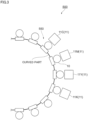
- FIG. 5 is a diagram showing a case in which the first inkjet head 11C, the second inkjet head 11M, and the moving unit 550 are viewed from a direction of the arrow V in FIG. 1 .
- each of the stop locations P, where the moving unit 550 stops is provided with a servomotor M, as an example of a driving source that rotates the can body 10.
- the servomotors M for rotating the can bodies 10 supported by the moving units 550 are provided beside the annular moving route 732 of the moving units 550.
- the driving sources (servomotors M) for rotating the can bodies 10 are not provided to the moving units 550, but are provided to the main body side of the print system 500.
- the driving sources for rotating the can bodies 10 are not provided to the moving units 550, but are provided to locations different from the moving units 550.
- the moving units 550 can be made light, and therefore, vibrations of the print system 500 caused by movement of the moving units 550 are reduced.
- the moving unit 550 is provided with the driving source, and thereby the moving unit 550 has a large weight, vibrations of the print system 500 when the moving units 550 are stopped are likely to be increased. Then, in this case, the inkjet heads 11 and the like vibrate, to thereby lead to degradation of image quality.
- the moving unit 550 in the configuration in which the driving sources are provided to the main body side of the print system 500, the moving unit 550 is made lighter in weight, and thereby vibrations of the print system 500 when the moving units 550 are stopped are reduced.
- the moving unit 550 is provided with the pedestal part 551.
- two can bodies 10 are provided on the pedestal part 551.
- the support member 20 is inserted into each of the can bodies 10; accordingly, the can body 10 is supported by the support member 20.
- the description is given by taking the case in which the two can bodies 10 are provided on the single moving unit 550 as an example; however, three or more can bodies 10 may be provided on the single moving unit 550.
- the moving unit 550 is provided with a transmission shaft 555 for transmitting the rotational driving force to the can body 10; in the exemplary embodiment, the rotational driving force from the servomotor M is transmitted to the can body 10 via the transmission shaft 555.
- a rotation gear 556 to be in contact with each of the support members 20 to rotate the support member 20 is provided.
- the rotation gear 556 is rotated by the transmission shaft 555, and thereby the can body 10 is rotated in the circumferential direction. Note that, in the exemplary embodiment, the two can bodies 10 provided on each moving unit 550 are rotated in the same direction.
- transmitting of the driving force from the servomotor M, which is the driving source, to the moving unit 550 is carried out by the so-called magnet coupling.
- a driving-source-side rotation body 581 rotated by the servomotor M is provided on the servomotor M side (main body side of the print system 500).
- a moving-body-side rotation body 582 is provided on the moving unit 550 side, the moving-body-side rotation body 582 being provided coaxially with the transmission shaft 555.
- the can body 10 is rotated by the driving force transmitted from the driving-source-side rotation body 581 to the moving-body-side rotation body 582.
- the moving-body-side rotation body 582 rotates in synchronization with the driving-source-side rotation body 581 by use of the magnetic force, and thereby the driving force is transmitted from the driving-source-side rotation body 581 to the moving-body-side rotation body 582.
- the magnet is provided to at least one of the driving-source-side rotation body 581 and the moving-body-side rotation body 582, and an attracted body attracted by the magnet is provided to the other one.
- the magnetic force generated in the magnet is used to rotate the moving-body-side rotation body 582 in synchronization with the driving-source-side rotation body 581.
- the transmission shaft 555 is rotated in response thereto; with this, the can body 10 rotates in the circumferential direction.
- the driving-source-side rotation body 581 and the moving-body-side rotation body 582 are disposed to face each other as shown in FIG. 5 .
- the driving-source-side rotation body 581 and the moving-body-side rotation body 582 are disposed in the non-contact state at this time.
- the moving unit 550 is moved by using a so-called linear motor mechanism, but movement of the moving unit 550 is not limited to the linear motor mechanism; for example, the movement may be performed by attaching the moving unit 550 to an endless member (a member such as a belt or a chain) and orbitally moving the endless member.
- an endless member a member such as a belt or a chain
- a driving source such as a motor
- a driving source for moving the moving unit 550 to each of the moving units 550, to thereby move the moving unit 550 autonomously.
- the driving source (servomotor M) was provided to the installation location of the inkjet head 11 ; however, the driving sources are provided to other locations, such as the first inspection device 92 (refer to FIG. 1 ), the light irradiation part 750, the second inspection device 300, and the protection layer forming part 770.
- the can body 10 is rotated by the driving source provided separately from the moving unit 550.
- the description was given by taking the case in which the driving-source-side rotation body 581 and the moving-body-side rotation body 582 were disposed in the non-contact state as an example; however, the driving-source-side rotation body 581 and the moving-body-side rotation body 582 may be disposed in the contact state, to thereby supply the driving force to the can body 10 through the driving-source-side rotation body 581 and the moving-body-side rotation body 582 that are in contact with each other.
- the driving source (servomotor M) for rotating the can body 10 was provided to the location other than the moving unit 550; however, the driving source for rotating the can body 10 may be provided to the moving unit 550.
- the moving unit 550 when the moving unit 550 is turned upside down, it is necessary to rotate the moving unit 550 around a predetermined rotation axis; there are plural modes of rotation around the rotation axis.
- the moving unit 550 was rotated around the rotation axis that was in parallel with the transmission shaft 555 shown in FIG. 5 .
- the moving unit 550 was rotated around the rotation axis that was in parallel with the axial direction of the can body 10.
- the rotation modes of the moving unit 550 are not limited thereto; for example, the moving unit 550 may be rotated around a rotation axis (not shown) extending along the direction indicated by the reference sign 5X in FIG. 5 . To put it another way, the moving unit 550 may be rotated around a rotation axis extending along the direction perpendicular to the axial direction of the can body 10. More specifically, the moving unit 550 may be rotated in the direction indicated by the reference sign 5Y in FIG. 5 .
Landscapes
- Engineering & Computer Science (AREA)
- Manufacturing & Machinery (AREA)
- Ink Jet (AREA)
- Coating Apparatus (AREA)
- Printing Methods (AREA)
Claims (5)
- Système d'impression (500) comprenant :un corps mobile (550) soutenant un corps (10) de canette et se déplaçant ;un trajet de déplacement supérieur (930) qui est prévu sous la forme d'un trajet de déplacement de forme linéaire, qui s'étend dans une direction latérale, et que le corps mobile (550) parcourt lorsque le corps mobile (550) se déplace dans une direction ;un trajet de déplacement inférieur (940) qui est prévu sous la forme d'un trajet de déplacement de forme linéaire, qui est positionné en dessous du trajet de déplacement supérieur (930), qui s'étend dans la direction latérale et que le corps mobile (550) parcourt lorsque le corps mobile (550) se déplace dans une direction opposée à la direction ;un premier trajet de déplacement linéaire (910) formé linéairement du côté supérieur au côté inférieur et prévoyant un premier dispositif d'inspection (92) au niveau de son côté latéral ;un second trajet de déplacement linéaire (920) formé linéairement du côté inférieur au côté supérieur et prévoyant un second dispositif d'inspection (300) au niveau de son côté latéral ; etune unité (700) de formation d'image effectuant une formation d'image sur le corps (10) de canette soutenu par le corps mobile (550), la formation d'image étant effectuée tandis que le corps (10) de canette soutenu par le corps mobile (550) est situé sur le trajet de déplacement supérieur (930) ou le trajet de déplacement inférieur (940), dans lequel,lorsque l'orientation du corps mobile (550) tandis que le corps mobile (550) est situé sur le trajet de déplacement supérieur (930) et l'orientation du corps mobile (550) tandis que le corps mobile (550) est situé sur le trajet de déplacement inférieur (940) sont comparées, le haut et le bas du corps mobile (550) sont inversés, etdans lequel le trajet de déplacement supérieur (930), le premier trajet de déplacement linéaire (910), le trajet de déplacement inférieur (940), et le second trajet de déplacement linéaire (920) sont prévus sur un trajet de déplacement annulaire (732).
- Système d'impression selon la revendication 1, comprenant en outre :une partie de guidage prévue le long du trajet de déplacement annulaire et guidant le corps mobile, dans lequel le corps mobile comprend une partie guidée devant être guidée par la partie de guidage et une partie de soutien de corps de canette devant être insérée dans le corps de canette pour soutenir le corps de canette,la partie de soutien de corps de canette est positionnée au-dessus de la partie guidée tandis que le corps mobile est situé sur le trajet de déplacement supérieur, etla partie de soutien de corps de canette est positionnée en dessous de la partie guidée tandis que le corps mobile est situé sur le trajet de déplacement inférieur.
- Système d'impression selon la revendication 1, dans lequel le trajet de déplacement supérieur et le trajet de déplacement inférieur sont disposés parallèlement l'un à l'autre.
- Système d'impression selon la revendication 3, dans lequel, lorsque le trajet de déplacement supérieur et le trajet de déplacement inférieur sont projetés vers le bas dans une direction verticale, le trajet de déplacement supérieur et le trajet de déplacement inférieur se chevauchent.
- Système d'impression selon la revendication 1, dans lequel le trajet de déplacement annulaire est disposé sur un plan s'étendant le long d'une direction verticale.
Applications Claiming Priority (2)
| Application Number | Priority Date | Filing Date | Title |
|---|---|---|---|
| JP2019055646A JP7573360B2 (ja) | 2019-03-22 | 2019-03-22 | 印刷システム |
| PCT/JP2020/000447 WO2020194998A1 (fr) | 2019-03-22 | 2020-01-09 | Système d'impression |
Publications (3)
| Publication Number | Publication Date |
|---|---|
| EP3943306A1 EP3943306A1 (fr) | 2022-01-26 |
| EP3943306A4 EP3943306A4 (fr) | 2022-05-11 |
| EP3943306B1 true EP3943306B1 (fr) | 2024-06-26 |
Family
ID=72557367
Family Applications (1)
| Application Number | Title | Priority Date | Filing Date |
|---|---|---|---|
| EP20777299.7A Active EP3943306B1 (fr) | 2019-03-22 | 2020-01-09 | Système d'impression |
Country Status (5)
| Country | Link |
|---|---|
| US (1) | US20220126600A1 (fr) |
| EP (1) | EP3943306B1 (fr) |
| JP (1) | JP7573360B2 (fr) |
| CN (1) | CN113302061B (fr) |
| WO (1) | WO2020194998A1 (fr) |
Families Citing this family (2)
| Publication number | Priority date | Publication date | Assignee | Title |
|---|---|---|---|---|
| JP7517938B2 (ja) * | 2020-10-02 | 2024-07-17 | アルテミラ株式会社 | 印刷装置 |
| JP7470612B2 (ja) * | 2020-10-12 | 2024-04-18 | アルテミラ株式会社 | 印刷装置 |
Family Cites Families (16)
| Publication number | Priority date | Publication date | Assignee | Title |
|---|---|---|---|---|
| US6769357B1 (en) * | 2003-06-05 | 2004-08-03 | Sequa Can Machinery, Inc. | Digital can decorating apparatus |
| DE102006034060B4 (de) * | 2006-07-20 | 2009-01-15 | Ball Packaging Europe Gmbh | Verfahren und Vorrichtung zum Dekorieren einer unebenen Fläche an einem formstabilen Objekt |
| CN103502100B (zh) * | 2011-04-25 | 2015-10-14 | 昭和铝罐株式会社 | 图像形成装置及形成有图像的罐体的制造方法 |
| JP5891602B2 (ja) | 2011-04-28 | 2016-03-23 | 東洋製罐株式会社 | インクジェット印刷装置及びこれを用いたシームレス缶の印刷方法 |
| FR2985683B1 (fr) * | 2012-01-16 | 2014-02-28 | Jean Luc Perret | Machine d'impression sur articles en trois dimensions et procede d'impression |
| DE102013218403A1 (de) * | 2013-09-13 | 2015-03-19 | Krones Ag | Vorrichtung und Verfahren zum Transport von Behältern in einer Behälterbehandlungsanlage |
| JP6255212B2 (ja) * | 2013-10-25 | 2017-12-27 | 昭和アルミニウム缶株式会社 | 缶体の製造方法、印刷装置、および、飲料用缶 |
| CA2966768A1 (fr) * | 2014-11-13 | 2016-05-19 | The Procter & Gamble Company | Procede de decoration d'un article |
| CN107848295B (zh) * | 2015-08-05 | 2020-04-21 | 昭和铝罐株式会社 | 印刷装置 |
| CN108778750B (zh) * | 2016-04-28 | 2020-09-08 | 昭和铝罐株式会社 | 印刷装置 |
| WO2017187863A1 (fr) * | 2016-04-28 | 2017-11-02 | 昭和アルミニウム缶株式会社 | Dispositif d'impression |
| JP6745229B2 (ja) * | 2016-07-08 | 2020-08-26 | 昭和アルミニウム缶株式会社 | 印刷装置 |
| EP3535129B1 (fr) * | 2016-11-02 | 2021-12-22 | Tonejet Limited | Machine d'impression |
| JP7075212B2 (ja) * | 2017-12-27 | 2022-05-25 | 昭和アルミニウム缶株式会社 | 印刷装置 |
| JP7123556B2 (ja) * | 2017-12-27 | 2022-08-23 | アルテミラ株式会社 | 印刷装置 |
| JP7257232B2 (ja) * | 2019-04-17 | 2023-04-13 | コニカミノルタ株式会社 | 画像検査装置、画像検査方法、画像検査プログラム、および、画像形成システム |
-
2019
- 2019-03-22 JP JP2019055646A patent/JP7573360B2/ja active Active
-
2020
- 2020-01-09 EP EP20777299.7A patent/EP3943306B1/fr active Active
- 2020-01-09 WO PCT/JP2020/000447 patent/WO2020194998A1/fr not_active Ceased
- 2020-01-09 US US17/427,660 patent/US20220126600A1/en not_active Abandoned
- 2020-01-09 CN CN202080009829.1A patent/CN113302061B/zh not_active Expired - Fee Related
Also Published As
| Publication number | Publication date |
|---|---|
| JP2020152086A (ja) | 2020-09-24 |
| WO2020194998A1 (fr) | 2020-10-01 |
| CN113302061A (zh) | 2021-08-24 |
| EP3943306A4 (fr) | 2022-05-11 |
| US20220126600A1 (en) | 2022-04-28 |
| EP3943306A1 (fr) | 2022-01-26 |
| CN113302061B (zh) | 2023-05-23 |
| JP7573360B2 (ja) | 2024-10-25 |
Similar Documents
| Publication | Publication Date | Title |
|---|---|---|
| EP3733412B1 (fr) | Appareil d'impression | |
| EP3901048B1 (fr) | Système d'impression | |
| CN108778750A (zh) | 印刷装置 | |
| EP3943306B1 (fr) | Système d'impression | |
| US11186097B2 (en) | Printing apparatus | |
| JP2023101785A (ja) | 印刷システムおよび缶体の製造方法 | |
| EP4227101B1 (fr) | Dispositif d'impression | |
| JP7270805B2 (ja) | 印刷装置 | |
| EP3851288A1 (fr) | Dispositif d'impression |
Legal Events
| Date | Code | Title | Description |
|---|---|---|---|
| STAA | Information on the status of an ep patent application or granted ep patent |
Free format text: STATUS: THE INTERNATIONAL PUBLICATION HAS BEEN MADE |
|
| PUAI | Public reference made under article 153(3) epc to a published international application that has entered the european phase |
Free format text: ORIGINAL CODE: 0009012 |
|
| STAA | Information on the status of an ep patent application or granted ep patent |
Free format text: STATUS: REQUEST FOR EXAMINATION WAS MADE |
|
| 17P | Request for examination filed |
Effective date: 20210809 |
|
| AK | Designated contracting states |
Kind code of ref document: A1 Designated state(s): AL AT BE BG CH CY CZ DE DK EE ES FI FR GB GR HR HU IE IS IT LI LT LU LV MC MK MT NL NO PL PT RO RS SE SI SK SM TR |
|
| RAP3 | Party data changed (applicant data changed or rights of an application transferred) |
Owner name: SHOWA ALUMINIUM CAN GLOBAL CORPORATION |
|
| RAP1 | Party data changed (applicant data changed or rights of an application transferred) |
Owner name: SHOWA ALUMINUM CAN CORPORATION |
|
| A4 | Supplementary search report drawn up and despatched |
Effective date: 20220408 |
|
| RIC1 | Information provided on ipc code assigned before grant |
Ipc: B41J 11/00 20060101ALI20220404BHEP Ipc: B41J 3/407 20060101ALI20220404BHEP Ipc: B65D 25/20 20060101ALI20220404BHEP Ipc: B65D 8/00 20060101ALI20220404BHEP Ipc: B41F 17/22 20060101ALI20220404BHEP Ipc: B05C 13/02 20060101ALI20220404BHEP Ipc: B05C 5/00 20060101ALI20220404BHEP Ipc: B41J 2/01 20060101AFI20220404BHEP |
|
| DAV | Request for validation of the european patent (deleted) | ||
| DAX | Request for extension of the european patent (deleted) | ||
| RAP3 | Party data changed (applicant data changed or rights of an application transferred) |
Owner name: ALTEMIRA CO., LTD. |
|
| RAP3 | Party data changed (applicant data changed or rights of an application transferred) |
Owner name: ALTEMIRA CO., LTD. |
|
| GRAP | Despatch of communication of intention to grant a patent |
Free format text: ORIGINAL CODE: EPIDOSNIGR1 |
|
| STAA | Information on the status of an ep patent application or granted ep patent |
Free format text: STATUS: GRANT OF PATENT IS INTENDED |
|
| INTG | Intention to grant announced |
Effective date: 20240220 |
|
| P01 | Opt-out of the competence of the unified patent court (upc) registered |
Effective date: 20240328 |
|
| GRAS | Grant fee paid |
Free format text: ORIGINAL CODE: EPIDOSNIGR3 |
|
| GRAA | (expected) grant |
Free format text: ORIGINAL CODE: 0009210 |
|
| STAA | Information on the status of an ep patent application or granted ep patent |
Free format text: STATUS: THE PATENT HAS BEEN GRANTED |
|
| RIN1 | Information on inventor provided before grant (corrected) |
Inventor name: TAKADA, HIROKI Inventor name: IKEDA, KAZUNORI Inventor name: OJIMA, SHINICHI |
|
| AK | Designated contracting states |
Kind code of ref document: B1 Designated state(s): AL AT BE BG CH CY CZ DE DK EE ES FI FR GB GR HR HU IE IS IT LI LT LU LV MC MK MT NL NO PL PT RO RS SE SI SK SM TR |
|
| REG | Reference to a national code |
Ref country code: GB Ref legal event code: FG4D |
|
| REG | Reference to a national code |
Ref country code: CH Ref legal event code: EP |
|
| REG | Reference to a national code |
Ref country code: DE Ref legal event code: R096 Ref document number: 602020033043 Country of ref document: DE |
|
| PG25 | Lapsed in a contracting state [announced via postgrant information from national office to epo] |
Ref country code: BG Free format text: LAPSE BECAUSE OF FAILURE TO SUBMIT A TRANSLATION OF THE DESCRIPTION OR TO PAY THE FEE WITHIN THE PRESCRIBED TIME-LIMIT Effective date: 20240626 |
|
| PG25 | Lapsed in a contracting state [announced via postgrant information from national office to epo] |
Ref country code: FI Free format text: LAPSE BECAUSE OF FAILURE TO SUBMIT A TRANSLATION OF THE DESCRIPTION OR TO PAY THE FEE WITHIN THE PRESCRIBED TIME-LIMIT Effective date: 20240626 Ref country code: HR Free format text: LAPSE BECAUSE OF FAILURE TO SUBMIT A TRANSLATION OF THE DESCRIPTION OR TO PAY THE FEE WITHIN THE PRESCRIBED TIME-LIMIT Effective date: 20240626 |
|
| REG | Reference to a national code |
Ref country code: LT Ref legal event code: MG9D |
|
| PG25 | Lapsed in a contracting state [announced via postgrant information from national office to epo] |
Ref country code: GR Free format text: LAPSE BECAUSE OF FAILURE TO SUBMIT A TRANSLATION OF THE DESCRIPTION OR TO PAY THE FEE WITHIN THE PRESCRIBED TIME-LIMIT Effective date: 20240927 |
|
| PG25 | Lapsed in a contracting state [announced via postgrant information from national office to epo] |
Ref country code: LV Free format text: LAPSE BECAUSE OF FAILURE TO SUBMIT A TRANSLATION OF THE DESCRIPTION OR TO PAY THE FEE WITHIN THE PRESCRIBED TIME-LIMIT Effective date: 20240626 |
|
| REG | Reference to a national code |
Ref country code: NL Ref legal event code: MP Effective date: 20240626 |
|
| PG25 | Lapsed in a contracting state [announced via postgrant information from national office to epo] |
Ref country code: NO Free format text: LAPSE BECAUSE OF FAILURE TO SUBMIT A TRANSLATION OF THE DESCRIPTION OR TO PAY THE FEE WITHIN THE PRESCRIBED TIME-LIMIT Effective date: 20240926 Ref country code: LV Free format text: LAPSE BECAUSE OF FAILURE TO SUBMIT A TRANSLATION OF THE DESCRIPTION OR TO PAY THE FEE WITHIN THE PRESCRIBED TIME-LIMIT Effective date: 20240626 Ref country code: HR Free format text: LAPSE BECAUSE OF FAILURE TO SUBMIT A TRANSLATION OF THE DESCRIPTION OR TO PAY THE FEE WITHIN THE PRESCRIBED TIME-LIMIT Effective date: 20240626 Ref country code: GR Free format text: LAPSE BECAUSE OF FAILURE TO SUBMIT A TRANSLATION OF THE DESCRIPTION OR TO PAY THE FEE WITHIN THE PRESCRIBED TIME-LIMIT Effective date: 20240927 Ref country code: FI Free format text: LAPSE BECAUSE OF FAILURE TO SUBMIT A TRANSLATION OF THE DESCRIPTION OR TO PAY THE FEE WITHIN THE PRESCRIBED TIME-LIMIT Effective date: 20240626 Ref country code: BG Free format text: LAPSE BECAUSE OF FAILURE TO SUBMIT A TRANSLATION OF THE DESCRIPTION OR TO PAY THE FEE WITHIN THE PRESCRIBED TIME-LIMIT Effective date: 20240626 Ref country code: RS Free format text: LAPSE BECAUSE OF FAILURE TO SUBMIT A TRANSLATION OF THE DESCRIPTION OR TO PAY THE FEE WITHIN THE PRESCRIBED TIME-LIMIT Effective date: 20240926 |
|
| PG25 | Lapsed in a contracting state [announced via postgrant information from national office to epo] |
Ref country code: NL Free format text: LAPSE BECAUSE OF FAILURE TO SUBMIT A TRANSLATION OF THE DESCRIPTION OR TO PAY THE FEE WITHIN THE PRESCRIBED TIME-LIMIT Effective date: 20240626 |
|
| REG | Reference to a national code |
Ref country code: AT Ref legal event code: MK05 Ref document number: 1697395 Country of ref document: AT Kind code of ref document: T Effective date: 20240626 |
|
| PG25 | Lapsed in a contracting state [announced via postgrant information from national office to epo] |
Ref country code: NL Free format text: LAPSE BECAUSE OF FAILURE TO SUBMIT A TRANSLATION OF THE DESCRIPTION OR TO PAY THE FEE WITHIN THE PRESCRIBED TIME-LIMIT Effective date: 20240626 |
|
| PG25 | Lapsed in a contracting state [announced via postgrant information from national office to epo] |
Ref country code: PT Free format text: LAPSE BECAUSE OF FAILURE TO SUBMIT A TRANSLATION OF THE DESCRIPTION OR TO PAY THE FEE WITHIN THE PRESCRIBED TIME-LIMIT Effective date: 20241028 |
|
| PG25 | Lapsed in a contracting state [announced via postgrant information from national office to epo] |
Ref country code: PT Free format text: LAPSE BECAUSE OF FAILURE TO SUBMIT A TRANSLATION OF THE DESCRIPTION OR TO PAY THE FEE WITHIN THE PRESCRIBED TIME-LIMIT Effective date: 20241028 |
|
| PG25 | Lapsed in a contracting state [announced via postgrant information from national office to epo] |
Ref country code: PL Free format text: LAPSE BECAUSE OF FAILURE TO SUBMIT A TRANSLATION OF THE DESCRIPTION OR TO PAY THE FEE WITHIN THE PRESCRIBED TIME-LIMIT Effective date: 20240626 |
|
| PG25 | Lapsed in a contracting state [announced via postgrant information from national office to epo] |
Ref country code: EE Free format text: LAPSE BECAUSE OF FAILURE TO SUBMIT A TRANSLATION OF THE DESCRIPTION OR TO PAY THE FEE WITHIN THE PRESCRIBED TIME-LIMIT Effective date: 20240626 |
|
| PG25 | Lapsed in a contracting state [announced via postgrant information from national office to epo] |
Ref country code: AT Free format text: LAPSE BECAUSE OF FAILURE TO SUBMIT A TRANSLATION OF THE DESCRIPTION OR TO PAY THE FEE WITHIN THE PRESCRIBED TIME-LIMIT Effective date: 20240626 Ref country code: IS Free format text: LAPSE BECAUSE OF FAILURE TO SUBMIT A TRANSLATION OF THE DESCRIPTION OR TO PAY THE FEE WITHIN THE PRESCRIBED TIME-LIMIT Effective date: 20241026 |
|
| PG25 | Lapsed in a contracting state [announced via postgrant information from national office to epo] |
Ref country code: CZ Free format text: LAPSE BECAUSE OF FAILURE TO SUBMIT A TRANSLATION OF THE DESCRIPTION OR TO PAY THE FEE WITHIN THE PRESCRIBED TIME-LIMIT Effective date: 20240626 |
|
| PG25 | Lapsed in a contracting state [announced via postgrant information from national office to epo] |
Ref country code: RO Free format text: LAPSE BECAUSE OF FAILURE TO SUBMIT A TRANSLATION OF THE DESCRIPTION OR TO PAY THE FEE WITHIN THE PRESCRIBED TIME-LIMIT Effective date: 20240626 Ref country code: SK Free format text: LAPSE BECAUSE OF FAILURE TO SUBMIT A TRANSLATION OF THE DESCRIPTION OR TO PAY THE FEE WITHIN THE PRESCRIBED TIME-LIMIT Effective date: 20240626 |
|
| PG25 | Lapsed in a contracting state [announced via postgrant information from national office to epo] |
Ref country code: ES Free format text: LAPSE BECAUSE OF FAILURE TO SUBMIT A TRANSLATION OF THE DESCRIPTION OR TO PAY THE FEE WITHIN THE PRESCRIBED TIME-LIMIT Effective date: 20240626 Ref country code: SM Free format text: LAPSE BECAUSE OF FAILURE TO SUBMIT A TRANSLATION OF THE DESCRIPTION OR TO PAY THE FEE WITHIN THE PRESCRIBED TIME-LIMIT Effective date: 20240626 |
|
| PG25 | Lapsed in a contracting state [announced via postgrant information from national office to epo] |
Ref country code: SM Free format text: LAPSE BECAUSE OF FAILURE TO SUBMIT A TRANSLATION OF THE DESCRIPTION OR TO PAY THE FEE WITHIN THE PRESCRIBED TIME-LIMIT Effective date: 20240626 Ref country code: SK Free format text: LAPSE BECAUSE OF FAILURE TO SUBMIT A TRANSLATION OF THE DESCRIPTION OR TO PAY THE FEE WITHIN THE PRESCRIBED TIME-LIMIT Effective date: 20240626 Ref country code: RO Free format text: LAPSE BECAUSE OF FAILURE TO SUBMIT A TRANSLATION OF THE DESCRIPTION OR TO PAY THE FEE WITHIN THE PRESCRIBED TIME-LIMIT Effective date: 20240626 Ref country code: PL Free format text: LAPSE BECAUSE OF FAILURE TO SUBMIT A TRANSLATION OF THE DESCRIPTION OR TO PAY THE FEE WITHIN THE PRESCRIBED TIME-LIMIT Effective date: 20240626 Ref country code: IS Free format text: LAPSE BECAUSE OF FAILURE TO SUBMIT A TRANSLATION OF THE DESCRIPTION OR TO PAY THE FEE WITHIN THE PRESCRIBED TIME-LIMIT Effective date: 20241026 Ref country code: ES Free format text: LAPSE BECAUSE OF FAILURE TO SUBMIT A TRANSLATION OF THE DESCRIPTION OR TO PAY THE FEE WITHIN THE PRESCRIBED TIME-LIMIT Effective date: 20240626 Ref country code: EE Free format text: LAPSE BECAUSE OF FAILURE TO SUBMIT A TRANSLATION OF THE DESCRIPTION OR TO PAY THE FEE WITHIN THE PRESCRIBED TIME-LIMIT Effective date: 20240626 Ref country code: CZ Free format text: LAPSE BECAUSE OF FAILURE TO SUBMIT A TRANSLATION OF THE DESCRIPTION OR TO PAY THE FEE WITHIN THE PRESCRIBED TIME-LIMIT Effective date: 20240626 Ref country code: AT Free format text: LAPSE BECAUSE OF FAILURE TO SUBMIT A TRANSLATION OF THE DESCRIPTION OR TO PAY THE FEE WITHIN THE PRESCRIBED TIME-LIMIT Effective date: 20240626 |
|
| PG25 | Lapsed in a contracting state [announced via postgrant information from national office to epo] |
Ref country code: IT Free format text: LAPSE BECAUSE OF FAILURE TO SUBMIT A TRANSLATION OF THE DESCRIPTION OR TO PAY THE FEE WITHIN THE PRESCRIBED TIME-LIMIT Effective date: 20240626 |
|
| REG | Reference to a national code |
Ref country code: DE Ref legal event code: R097 Ref document number: 602020033043 Country of ref document: DE |
|
| PG25 | Lapsed in a contracting state [announced via postgrant information from national office to epo] |
Ref country code: DK Free format text: LAPSE BECAUSE OF FAILURE TO SUBMIT A TRANSLATION OF THE DESCRIPTION OR TO PAY THE FEE WITHIN THE PRESCRIBED TIME-LIMIT Effective date: 20240626 |
|
| PLBE | No opposition filed within time limit |
Free format text: ORIGINAL CODE: 0009261 |
|
| STAA | Information on the status of an ep patent application or granted ep patent |
Free format text: STATUS: NO OPPOSITION FILED WITHIN TIME LIMIT |
|
| 26N | No opposition filed |
Effective date: 20250327 |
|
| REG | Reference to a national code |
Ref country code: DE Ref legal event code: R119 Ref document number: 602020033043 Country of ref document: DE |
|
| REG | Reference to a national code |
Ref country code: CH Ref legal event code: PL |
|
| PG25 | Lapsed in a contracting state [announced via postgrant information from national office to epo] |
Ref country code: SE Free format text: LAPSE BECAUSE OF FAILURE TO SUBMIT A TRANSLATION OF THE DESCRIPTION OR TO PAY THE FEE WITHIN THE PRESCRIBED TIME-LIMIT Effective date: 20240626 |
|
| PG25 | Lapsed in a contracting state [announced via postgrant information from national office to epo] |
Ref country code: LU Free format text: LAPSE BECAUSE OF NON-PAYMENT OF DUE FEES Effective date: 20250109 Ref country code: MC Free format text: LAPSE BECAUSE OF FAILURE TO SUBMIT A TRANSLATION OF THE DESCRIPTION OR TO PAY THE FEE WITHIN THE PRESCRIBED TIME-LIMIT Effective date: 20240626 |
|
| PG25 | Lapsed in a contracting state [announced via postgrant information from national office to epo] |
Ref country code: DE Free format text: LAPSE BECAUSE OF NON-PAYMENT OF DUE FEES Effective date: 20250801 |
|
| PG25 | Lapsed in a contracting state [announced via postgrant information from national office to epo] |
Ref country code: BE Free format text: LAPSE BECAUSE OF NON-PAYMENT OF DUE FEES Effective date: 20250131 |
|
| PG25 | Lapsed in a contracting state [announced via postgrant information from national office to epo] |
Ref country code: FR Free format text: LAPSE BECAUSE OF NON-PAYMENT OF DUE FEES Effective date: 20250131 |
|
| PG25 | Lapsed in a contracting state [announced via postgrant information from national office to epo] |
Ref country code: CH Free format text: LAPSE BECAUSE OF NON-PAYMENT OF DUE FEES Effective date: 20250131 |
|
| REG | Reference to a national code |
Ref country code: BE Ref legal event code: MM Effective date: 20250131 |
|
| PG25 | Lapsed in a contracting state [announced via postgrant information from national office to epo] |
Ref country code: IE Free format text: LAPSE BECAUSE OF NON-PAYMENT OF DUE FEES Effective date: 20250109 |
|
| PGFP | Annual fee paid to national office [announced via postgrant information from national office to epo] |
Ref country code: GB Payment date: 20260123 Year of fee payment: 7 |