EP3943323B1 - Luftauslassvorrichtung und luftauslassverfahren für eine klimaanlage eines fahrzeugs - Google Patents
Luftauslassvorrichtung und luftauslassverfahren für eine klimaanlage eines fahrzeugs Download PDFInfo
- Publication number
- EP3943323B1 EP3943323B1 EP20773938.4A EP20773938A EP3943323B1 EP 3943323 B1 EP3943323 B1 EP 3943323B1 EP 20773938 A EP20773938 A EP 20773938A EP 3943323 B1 EP3943323 B1 EP 3943323B1
- Authority
- EP
- European Patent Office
- Prior art keywords
- air
- air outlet
- doors
- vehicle
- vehicle display
- Prior art date
- Legal status (The legal status is an assumption and is not a legal conclusion. Google has not performed a legal analysis and makes no representation as to the accuracy of the status listed.)
- Active
Links
Images



Classifications
-
- B—PERFORMING OPERATIONS; TRANSPORTING
- B60—VEHICLES IN GENERAL
- B60H—ARRANGEMENTS OF HEATING, COOLING, VENTILATING OR OTHER AIR-TREATING DEVICES SPECIALLY ADAPTED FOR PASSENGER OR GOODS SPACES OF VEHICLES
- B60H1/00—Heating, cooling or ventilating devices
- B60H1/34—Nozzles; Air-diffusers
- B60H1/3414—Nozzles; Air-diffusers with means for adjusting the air stream direction
-
- B—PERFORMING OPERATIONS; TRANSPORTING
- B60—VEHICLES IN GENERAL
- B60H—ARRANGEMENTS OF HEATING, COOLING, VENTILATING OR OTHER AIR-TREATING DEVICES SPECIALLY ADAPTED FOR PASSENGER OR GOODS SPACES OF VEHICLES
- B60H1/00—Heating, cooling or ventilating devices
- B60H1/00642—Control systems or circuits; Control members or indication devices for heating, cooling or ventilating devices
- B60H1/00814—Control systems or circuits characterised by their output, for controlling particular components of the heating, cooling or ventilating installation
- B60H1/00821—Control systems or circuits characterised by their output, for controlling particular components of the heating, cooling or ventilating installation the components being ventilating, air admitting or air distributing devices
- B60H1/00835—Damper doors, e.g. position control
- B60H1/00842—Damper doors, e.g. position control the system comprising a plurality of damper doors; Air distribution between several outlets
-
- B—PERFORMING OPERATIONS; TRANSPORTING
- B60—VEHICLES IN GENERAL
- B60H—ARRANGEMENTS OF HEATING, COOLING, VENTILATING OR OTHER AIR-TREATING DEVICES SPECIALLY ADAPTED FOR PASSENGER OR GOODS SPACES OF VEHICLES
- B60H1/00—Heating, cooling or ventilating devices
- B60H1/24—Ventilating devices where the heating or cooling is irrelevant
- B60H1/241—Ventilating devices where the heating or cooling is irrelevant characterised by the location of ventilation devices in the vehicle
- B60H1/242—Ventilating devices where the heating or cooling is irrelevant characterised by the location of ventilation devices in the vehicle located in the front area
-
- B—PERFORMING OPERATIONS; TRANSPORTING
- B60—VEHICLES IN GENERAL
- B60H—ARRANGEMENTS OF HEATING, COOLING, VENTILATING OR OTHER AIR-TREATING DEVICES SPECIALLY ADAPTED FOR PASSENGER OR GOODS SPACES OF VEHICLES
- B60H1/00—Heating, cooling or ventilating devices
- B60H1/00642—Control systems or circuits; Control members or indication devices for heating, cooling or ventilating devices
- B60H1/00814—Control systems or circuits characterised by their output, for controlling particular components of the heating, cooling or ventilating installation
- B60H1/00821—Control systems or circuits characterised by their output, for controlling particular components of the heating, cooling or ventilating installation the components being ventilating, air admitting or air distributing devices
- B60H1/00871—Air directing means, e.g. blades in an air outlet
-
- B—PERFORMING OPERATIONS; TRANSPORTING
- B60—VEHICLES IN GENERAL
- B60H—ARRANGEMENTS OF HEATING, COOLING, VENTILATING OR OTHER AIR-TREATING DEVICES SPECIALLY ADAPTED FOR PASSENGER OR GOODS SPACES OF VEHICLES
- B60H1/00—Heating, cooling or ventilating devices
- B60H1/34—Nozzles; Air-diffusers
- B60H1/3414—Nozzles; Air-diffusers with means for adjusting the air stream direction
- B60H1/3421—Nozzles; Air-diffusers with means for adjusting the air stream direction using only pivoting shutters
-
- B—PERFORMING OPERATIONS; TRANSPORTING
- B60—VEHICLES IN GENERAL
- B60K—ARRANGEMENT OR MOUNTING OF PROPULSION UNITS OR OF TRANSMISSIONS IN VEHICLES; ARRANGEMENT OR MOUNTING OF PLURAL DIVERSE PRIME-MOVERS IN VEHICLES; AUXILIARY DRIVES FOR VEHICLES; INSTRUMENTATION OR DASHBOARDS FOR VEHICLES; ARRANGEMENTS IN CONNECTION WITH COOLING, AIR INTAKE, GAS EXHAUST OR FUEL SUPPLY OF PROPULSION UNITS IN VEHICLES
- B60K35/00—Instruments specially adapted for vehicles; Arrangement of instruments in or on vehicles
- B60K35/20—Output arrangements, i.e. from vehicle to user, associated with vehicle functions or specially adapted therefor
- B60K35/21—Output arrangements, i.e. from vehicle to user, associated with vehicle functions or specially adapted therefor using visual output, e.g. blinking lights or matrix displays
- B60K35/22—Display screens
-
- B—PERFORMING OPERATIONS; TRANSPORTING
- B60—VEHICLES IN GENERAL
- B60K—ARRANGEMENT OR MOUNTING OF PROPULSION UNITS OR OF TRANSMISSIONS IN VEHICLES; ARRANGEMENT OR MOUNTING OF PLURAL DIVERSE PRIME-MOVERS IN VEHICLES; AUXILIARY DRIVES FOR VEHICLES; INSTRUMENTATION OR DASHBOARDS FOR VEHICLES; ARRANGEMENTS IN CONNECTION WITH COOLING, AIR INTAKE, GAS EXHAUST OR FUEL SUPPLY OF PROPULSION UNITS IN VEHICLES
- B60K35/00—Instruments specially adapted for vehicles; Arrangement of instruments in or on vehicles
- B60K35/50—Instruments characterised by their means of attachment to or integration in the vehicle
- B60K35/53—Movable instruments, e.g. slidable
-
- B—PERFORMING OPERATIONS; TRANSPORTING
- B60—VEHICLES IN GENERAL
- B60K—ARRANGEMENT OR MOUNTING OF PROPULSION UNITS OR OF TRANSMISSIONS IN VEHICLES; ARRANGEMENT OR MOUNTING OF PLURAL DIVERSE PRIME-MOVERS IN VEHICLES; AUXILIARY DRIVES FOR VEHICLES; INSTRUMENTATION OR DASHBOARDS FOR VEHICLES; ARRANGEMENTS IN CONNECTION WITH COOLING, AIR INTAKE, GAS EXHAUST OR FUEL SUPPLY OF PROPULSION UNITS IN VEHICLES
- B60K35/00—Instruments specially adapted for vehicles; Arrangement of instruments in or on vehicles
- B60K35/60—Instruments characterised by their location or relative disposition in or on vehicles
-
- B—PERFORMING OPERATIONS; TRANSPORTING
- B60—VEHICLES IN GENERAL
- B60H—ARRANGEMENTS OF HEATING, COOLING, VENTILATING OR OTHER AIR-TREATING DEVICES SPECIALLY ADAPTED FOR PASSENGER OR GOODS SPACES OF VEHICLES
- B60H1/00—Heating, cooling or ventilating devices
- B60H1/00007—Combined heating, ventilating, or cooling devices
- B60H1/00021—Air flow details of HVAC devices
- B60H2001/00078—Assembling, manufacturing or layout details
- B60H2001/00092—Assembling, manufacturing or layout details of air deflecting or air directing means inside the device
-
- B—PERFORMING OPERATIONS; TRANSPORTING
- B60—VEHICLES IN GENERAL
- B60H—ARRANGEMENTS OF HEATING, COOLING, VENTILATING OR OTHER AIR-TREATING DEVICES SPECIALLY ADAPTED FOR PASSENGER OR GOODS SPACES OF VEHICLES
- B60H1/00—Heating, cooling or ventilating devices
- B60H1/34—Nozzles; Air-diffusers
- B60H2001/3471—Details of actuators
-
- B—PERFORMING OPERATIONS; TRANSPORTING
- B60—VEHICLES IN GENERAL
- B60H—ARRANGEMENTS OF HEATING, COOLING, VENTILATING OR OTHER AIR-TREATING DEVICES SPECIALLY ADAPTED FOR PASSENGER OR GOODS SPACES OF VEHICLES
- B60H1/00—Heating, cooling or ventilating devices
- B60H1/34—Nozzles; Air-diffusers
- B60H2001/3471—Details of actuators
- B60H2001/3478—Details of actuators acting on additional damper doors
-
- B—PERFORMING OPERATIONS; TRANSPORTING
- B60—VEHICLES IN GENERAL
- B60H—ARRANGEMENTS OF HEATING, COOLING, VENTILATING OR OTHER AIR-TREATING DEVICES SPECIALLY ADAPTED FOR PASSENGER OR GOODS SPACES OF VEHICLES
- B60H1/00—Heating, cooling or ventilating devices
- B60H1/34—Nozzles; Air-diffusers
- B60H2001/3485—Air temperature regulation
-
- B—PERFORMING OPERATIONS; TRANSPORTING
- B60—VEHICLES IN GENERAL
- B60K—ARRANGEMENT OR MOUNTING OF PROPULSION UNITS OR OF TRANSMISSIONS IN VEHICLES; ARRANGEMENT OR MOUNTING OF PLURAL DIVERSE PRIME-MOVERS IN VEHICLES; AUXILIARY DRIVES FOR VEHICLES; INSTRUMENTATION OR DASHBOARDS FOR VEHICLES; ARRANGEMENTS IN CONNECTION WITH COOLING, AIR INTAKE, GAS EXHAUST OR FUEL SUPPLY OF PROPULSION UNITS IN VEHICLES
- B60K2360/00—Indexing scheme associated with groups B60K35/00 or B60K37/00 relating to details of instruments or dashboards
- B60K2360/60—Structural details of dashboards or instruments
- B60K2360/65—Features of dashboards
- B60K2360/658—Dashboard parts used as air ducts
Definitions
- the present invention relates to an air outlet device for an air-conditioning system of a vehicle, a vehicle, and an air outlet method for an air-conditioning system of a vehicle.
- a technology of controlling air outlet states of air vents by rotating an in-vehicle display screen is provided.
- this technology is only applicable to a single display screen.
- Air vents need to be disposed around an in-vehicle display terminal, and the air outlet effect cannot be achieved in a case that there are a plurality of screens.
- the in-vehicle display screen has a development trend of large-screen and multi-screen. When air vents of an air outlet assembly are blocked, flow direction transmission of airflow cannot be implemented.
- US 2017/0291469 A1 discloses a ventilation register control system provided for a motor vehicle. That ventilation register control system includes four ventilation registers and a control module configured to independently open and close each ventilation register.
- US 2018/0141405 A1 discloses an air handling system for a vehicle comprising a conditioning section for controlling a temperature of a flow of air, a mixing section disposed downstream of the conditioning section with respect to a direction of the flow of the air, and a delivery section disposed downstream of the mixing section with respect to the direction of the flow of the air.
- the present invention is to at least resolve one of the technical problems in the related art to some extent.
- a first objective of the present invention is to provide an air outlet device for an air-conditioning system of a vehicle, to control an airflow direction by controlling opening and closing states of an air outlet assembly, thereby preventing airflow from being blocked, and satisfying the comfort of passengers.
- a second objective of the present invention is to provide a vehicle including the foregoing air outlet device.
- a third objective of the present invention is to provide an air outlet method for an air-conditioning system of a vehicle.
- a first aspect of the present invention provides an air outlet device for an air-conditioning system of a vehicle, as defined in independent claim 1.
- the control unit is connected to the plurality of driving components.
- the opening and closing states of the air outlet assembly can be controlled, so as to control an airflow direction, thereby preventing airflow from being blocked, and satisfying the comfort of passengers.
- the air outlet device for an air-conditioning system of a vehicle may further include the following additional technical features:
- the control unit is further configured to control first air doors among the plurality of first air doors in the blocked region and first air doors among the plurality of first air doors in the unblocked region to open, and control a corresponding in-vehicle display terminal in the blocked region to rotate, to change an air outlet direction.
- control unit is further configured to receive a user instruction, and control at least one of the first air doors in the blocked region to open according to the user instruction.
- the air outlet device further includes: a baffle configured to be disposed in an air duct of the air-conditioning system and to be disposed along a flow direction of air in the air duct, to divide the air duct into a plurality of partitioned air ducts; and a plurality of second air doors configured to be disposed between an evaporator and a warm box of the air-conditioning system, the evaporator is configured to generate cold air, and the warm box is configured to generate warm air, the plurality of second air doors being configured to be respectively disposed in the plurality of partitioned air ducts, and each of the second air doors being configured to control a flow rate of cold air in the corresponding partitioned air duct.
- the control unit is configured to control opening degrees of the plurality of second air doors.
- each partitioned air duct is configured to correspond to first air doors in a certain region.
- the control unit is further configured to obtain a target air outlet temperature of each of the unblocked regions, and control the opening degree of the second air door in the partitioned air duct corresponding to each of the unblocked regions according to the target air outlet temperature of each of the unblocked regions.
- the driving component includes: a gear, the gear being connected to the first air door to drive the first air door to move; a rack, the rack cooperating with the gear to drive the gear to rotate; and a motor, the motor being connected to the rack, and being configured to drive the rack under the control of the control unit.
- a second aspect of the present invention provides a vehicle, including the foregoing air outlet device for an air-conditioning system of a vehicle.
- the vehicle according to an embodiment of the present invention can control the airflow direction by using the foregoing air outlet device for an air-conditioning system of a vehicle, thereby preventing the airflow from being blocked, and satisfying the comfort of passengers.
- a third aspect of the present invention provides an air outlet method for an air-conditioning system of a vehicle, as defined in independent claim 7.
- the plurality of driving components are controlled to drive the plurality of first air doors to open or close independently, so as to control the airflow direction, thereby preventing the airflow from being blocked, and satisfying the comfort of passengers.
- the air outlet method for an air-conditioning system of a vehicle may further include the following additional technical features:
- the controlling the plurality of driving components according to the positions of the plurality of in-vehicle display terminals and rotation states of the plurality of in-vehicle display terminals includes: controlling first air doors among the plurality of first air doors in the blocked region and first air doors among the plurality of first air doors in the unblocked region to open, and controlling a corresponding in-vehicle display terminal in the blocked region to rotate, to change an air outlet direction.
- the foregoing air outlet method for an air-conditioning system of a vehicle further includes: receiving a user instruction, and controlling at least one of the first air doors in the blocked region to open according to the user instruction.
- the air-conditioning system includes an air duct, an evaporator, and a warm box.
- the evaporator is configured to generate cold air.
- the warm box is configured to generate warm air.
- a baffle is disposed in the air duct, and is disposed along a flow direction of air in the air duct, to divide the air duct into a plurality of partitioned air ducts.
- a plurality of second air doors are disposed between the evaporator and the warm box. The plurality of second air doors are respectively disposed in the plurality of partitioned air ducts. Each of the second air doors is configured to control a flow rate of cold air in the corresponding partitioned air duct.
- the air outlet method further includes: controlling opening degrees of the plurality of second air doors.
- each partitioned air duct corresponds to first air doors in a certain region.
- the controlling opening degrees of the plurality of second air doors includes: obtaining a target air outlet temperature of each of the unblocked regions; and controlling the opening degree of the second air door in the partitioned air duct corresponding to each of the unblocked regions according to the target air outlet temperature of each of the unblocked regions.
- FIG. 1 is a schematic block diagram of an air outlet device for an air-conditioning system of a vehicle according to some embodiments of the present invention.
- the air outlet device for an air-conditioning system of a vehicle includes: an air outlet assembly 10 disposed at air vents of the air-conditioning system and a control unit 20.
- the air outlet assembly 10 includes a plurality of first air doors 11 and a plurality of driving components 12.
- the plurality of driving components 12 are respectively connected to the plurality of first air doors 11.
- Each driving component 12 is configured to drive the corresponding first air door 11.
- the control unit 20 is connected to the plurality of driving components 12.
- the control unit 20 is configured to control the plurality of driving components 12 to drive the plurality of first air doors 11 to open or close independently.
- each driving component 12 may include: a gear 121, a rack 122, and a motor (not specifically shown in the figure).
- the gear 121 is connected to the corresponding first air door 11, to drive the first air door 11 to move.
- the rack 122 cooperates with the gear 121 to drive the gear 121 to rotate.
- the motor is connected to the rack 122, and is configured to drive the rack 122 under the control of the control unit 20.
- the air outlet assembly 10 is installed behind in-vehicle display terminals, such as being installed on a dashboard.
- the air outlet assembly 10 may have a structure extending left and right, and may be adaptively extended and contracted according to a quantity of the in-vehicle display terminals.
- the foregoing air outlet device for an air-conditioning system of a vehicle further includes: a position detection unit 30, configured to detect positions of a plurality of in-vehicle display terminals of the vehicle.
- the plurality of in-vehicle display terminals are disposed in front of the air outlet assembly 10.
- the control unit 20 controls the plurality of driving components 12 according to the positions of the plurality of in-vehicle display terminals and/or rotation states of the plurality of in-vehicle display terminals.
- the plurality of driving components 12 drive the plurality of first air doors 11 to open or close independently.
- a plurality of driving components drive a plurality of first air doors in a region blocked by the in-vehicle display terminal to close.
- the plurality of driving components 12 drive the plurality of first air doors to open or close independently. For example, as shown in FIG. 5
- rotation states of the in-vehicle display terminal A, an in-vehicle display terminal B, and an in-vehicle display terminal C are different, and quantities of first air doors that are blocked by the in-vehicle display terminals A, B, and C are also different.
- the control unit 20 controls a plurality of driving components in regions blocked by the in-vehicle display terminals A, B, and C to drive a plurality of corresponding first air doors to close, and controls a plurality of driving components outside the regions blocked by the in-vehicle display terminals A, B, and C to drive a plurality of corresponding first air doors to open, thereby achieving the air outlet effect and saving energy.
- the plurality of driving components are further controlled according to the positions of the plurality of in-vehicle display terminals and the rotation states of plurality of in-vehicle display terminals, to realize more precise control.
- control unit 20 is further configured to determine a blocked region and an unblocked region of the air outlet assembly 10 according to the positions of the plurality of in-vehicle display terminals and the rotation states of the plurality of in-vehicle display terminals, and control first air doors 11 in the blocked region to close and first air doors 11 in the unblocked region to open.
- the blocked region is an air outlet region of the air outlet assembly that is blocked by the in-vehicle display terminal, that is, a region from which the air outlet assembly cannot let out air.
- the unblocked region is an air outlet region of the air outlet assembly that is not blocked by the in-vehicle display terminal, that is, a region from which the air outlet assembly can normally let out air.
- all the first air doors 11 in the blocked region are controlled to be closed, which can save energy; and all the first air doors in the unblocked region are controlled to be open, which can satisfy a requirement for temperature adjustment of a driver.
- closing all the first air doors 11 in the blocked region can effectively avoid the continuous temperature rise in the blocked region, and equipment aging or safety hazards due to the temperature rise for a long time.
- an air outlet region where the certain first air door is located also belongs to the blocked region.
- the first air door is controlled to be closed.
- the in-vehicle display terminals are connected to universal ball heads for rotation, so as to change display directions of the in-vehicle display terminals.
- the in-vehicle display terminals slide left and right on a guide rail driven by drive motors of the in-vehicle display terminals, to change the positions of the in-vehicle display terminals.
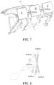
- the in-vehicle display terminals may be spliced together to form a large display screen, or may be combined into different forms. For example, as shown in FIG. 5 and FIG.
- A, B, and C represent the in-vehicle display terminals, and arrow directions represent movement directions and rotation directions of the in-vehicle display terminals. It is assumed that sizes of the in-vehicle display terminals A, B, and C are all 20 cm * 15 cm (length * width), a large display screen of 60 cm * 15 cm may be obtained by splicing as shown in FIG. 5 , and a large display screen of 45 cm * 20 cm may be obtained by splicing as shown in FIG. 6 .
- FIG. 5 FIG. 6 merely illustrate some embodiments of the present invention.
- the present invention includes but is not limited to three in-vehicle display terminals, and may alternatively include two or four in-vehicle display terminals, or the like.
- a laser sensor is disposed in the air outlet assembly 10.
- the laser sensor is configured to detect position information of the in-vehicle display terminals according to a distance setting, and transmit the position information to the control unit 20 through a controller area network (CAN) signal.
- the control unit 20 (for example, the control unit 20 may be a micro controller unit (MCU)) drives, according to received position information, the motors to control the first air doors 11 to open or close. For example, in a case that the position of the in-vehicle display terminal A blocks the corresponding first air doors 11, the control unit 20 controls the air doors corresponding to the position to close and the first air doors 11 corresponding to the unblocked regions to open.
- MCU micro controller unit
- the position detection unit 30 acquires the position of the in-vehicle display terminal.
- the control unit 20 controls the opening and closing states of the air vents at different positions.
- the quantities of the air vents that are blocked are different when the in-vehicle display terminal is in a landscape state and a portrait state.
- the quantities of the opening and closing states of the plurality of first air doors may also change correspondingly.
- the air doors that are blocked by the positions of the in-vehicle display terminals can be closed, and the air doors in the regions that are not blocked by the in-vehicle display terminals can be opened, so as to prevent airflow from being blocked by the in-vehicle display terminals.
- air can flow out from the unblocked regions, to maximize the energy of the airflow, thereby realizing energy conservation and environmental protection.
- control unit 20 is further configured to determine a blocked region and an unblocked region of the air outlet assembly 10 according to the positions of the plurality of in-vehicle display terminals and the rotation states of the plurality of in-vehicle display terminals, control all first air doors 11 in the blocked region and the unblocked region to open, and control the corresponding in-vehicle display terminal in the blocked region to rotate, so as to change an air outlet direction.
- control unit 20 is further configured to receive a user instruction, and control at least one of the first air doors 11 in the blocked region to open according to the user instruction.
- a temperature sensor (not shown in the figure) may be disposed on the in-vehicle display terminal to detect a temperature of the in-vehicle display terminal, and feed back a high-temperature region of the in-vehicle display terminal to the control unit 20.
- the control unit 20 may further control at least one of first air doors 11 corresponding to the high-temperature region of the in-vehicle display terminal in the blocked region to open, so as to dissipate heat from the in-vehicle display terminal; and control the universal ball head to rotate the in-vehicle display terminal, so as to change the air outlet direction of the first air door 11, thereby blowing air into the vehicle while dissipating heat from the in-vehicle display terminal. Blowing cold air can dissipate heat from the plurality of in-vehicle display terminals.
- the air-conditioning system may include an air duct 40, an evaporator 50, and a warm box 60.
- the evaporator 50 is configured to generate cold air.
- the warm box 60 is configured to generate warm air.
- the air outlet device 110 may further include: a baffle 70 disposed in the air duct 40, the baffle 70 being disposed along a flow direction of air in the air duct 40, to separate the air duct 40 into a plurality of partitioned air ducts (the plurality of partitioned air duct divide the air duct into a plurality of regions); and a plurality of second air doors 80 disposed between the evaporator and the warm box, the plurality of second air doors 80 being correspondingly disposed in the plurality of partitioned air ducts respectively, and each second air door being configured to control a flow rate of cold air in the corresponding partitioned air duct.
- the control unit 20 is configured to control opening degrees of the plurality of second air doors.
- Each partitioned air duct corresponds to first air doors in a certain region.
- the partitioned air duct in the upper part of the figure corresponds to controlling a plurality of first air doors in the unblocked region to open, to blow out warm airflow; and the partitioned air duct in the lower part of the figure corresponds to controlling a plurality of first air doors in the unblocked region to open, to blow out cold airflow.
- the upper part shown in FIG. 9 may also blow out cold airflow, and the lower part may also blow out warm airflow, which may be defined according to actual requirements.
- the second air doors are rotatable or movable.
- control unit 20 is further configured to obtain a target air outlet temperature of each unblocked region, and control the opening degree of the second air door in the partitioned air duct corresponding to each unblocked region according to the target air outlet temperature of each unblocked region.
- the present invention can further implement different air outlet temperatures in different air outlet regions.
- the airflow enters the partitioned air ducts through the isolated evaporator and the warm box with the baffle, and then flows out of the air outlet assembly.
- the second air doors air vent open-and-close units
- An opening and closing amount of each second air door is controlled to implement cooling and heating control.
- the control unit 20 may increase an opening degree of a corresponding second air door to increase a flow rate of cold airflow flowing through, so as to increase a flow rate of cold airflow entering the warm box and reduce a temperature of warm airflow flowing out of the warm box, thereby reducing the target air outlet temperature.
- the control unit 20 may increase an opening degree of a corresponding second air door to increase a flow rate of cold airflow flowing through, so as to increase a flow rate of cold airflow entering the warm box and reduce a temperature of warm airflow flowing out of the warm box, thereby reducing the target air outlet temperature.
- the opening degree of the second air door may be adjusted to satisfy the requirement of the driver.
- the opening and closing states of the air outlet assembly can be controlled through movement of the in-vehicle display terminals, to control the airflow direction, thereby preventing the airflow from being blocked.
- the airflow is controlled to dissipate heat from the in-vehicle display terminals.
- the direction of the airflow is guided through the in-vehicle display terminals, to satisfy the comfort of passengers.
- the control unit is connected to the plurality of driving components.
- the opening and closing states of the air outlet assembly can be controlled, so as to control an airflow direction, thereby preventing airflow from being blocked, and satisfying the comfort of passengers.
- FIG. 10 is a schematic block diagram of a vehicle according to an embodiment of the present invention.
- the vehicle 100 includes: the foregoing air outlet device 110 of an air-conditioning system of a vehicle.
- the vehicle according to an embodiment of the present invention can control the airflow direction by using the foregoing air outlet device for an air-conditioning system of a vehicle, thereby preventing the airflow from being blocked, and satisfying the comfort of passengers.
- the present invention further provides an air outlet method for an air-conditioning system of a vehicle.
- an air outlet assembly is disposed at air vents of the air-conditioning system.
- the air outlet assembly includes a plurality of first air doors and a plurality of driving components.
- the plurality of driving components are respectively connected to the plurality of first air doors.
- Each driving component is configured to drive the corresponding first air door.
- FIG. 11 is a flowchart of an air outlet method for an air-conditioning system of a vehicle according to an embodiment of the present invention.
- the air outlet method for an air-conditioning system of a vehicle includes the following step: S1. Control a plurality of driving components to drive a plurality of first air doors to open or close independently.
- the plurality of driving components are controlled to drive the plurality of first air doors to open or close independently, so as to control the airflow direction, thereby preventing the airflow from being blocked, and satisfying the comfort of passengers.
- first and second are used merely for the purpose of description, and shall not be construed as indicating or implying relative importance or implying a quantity of indicated technical features. Therefore, features defining “first” and “second” can explicitly or implicitly include at least one of the features. In the descriptions of the present invention, unless explicitly specified, “multiple” means at least two, for example, two or three.
- a sequenced list that may be considered as executable instructions used for implementing logical functions, may be specifically implemented in any computer readable medium to be used by an instruction execution system, apparatus, or device (for example, a computer-based system, a system including a processor, or another system that can obtain an instruction from the instruction execution system, apparatus, or device and execute the instruction) or to be used by combining such instruction execution systems, apparatuses, or devices.
- a "computer-readable medium" may be any apparatus that can include, store, communicate, propagate, or transmit the program for use by the instruction execution system, apparatus, or device or in combination with the instruction execution system, apparatus, or device.
- the computer-readable medium includes the following: an electrical connection (electronic device) having one or more wires, a portable computer diskette (magnetic apparatus), a random access memory (RAM), a read-only memory (ROM), an erasable programmable read-only memory (EPROM or flash memory), an optical fiber apparatus, and a portable compact disk read-only memory (CDROM).
- the computer-readable medium can even be paper or other suitable media on which the program can be printed, because the program can be obtained electronically by, for example, optically scanning paper or other media, then editing, interpreting, or processing in other suitable ways if necessary, and then storing it in a computer memory.
- parts of the present invention can be implemented by using hardware, software, firmware, or a combination thereof.
- a plurality of steps or methods may be implemented by using software or firmware that are stored in a memory and are executed by a proper instruction execution system.
- implementation may be performed by any one of the following technologies well known in the art or a combination thereof: a discrete logic circuit of a logic gate circuit for realizing a logic function for a data signal, an application-specific integrated circuit having a suitable combined logic gate circuit, a programmable gate array (PGA), and a field programmable gate array (FPGA).
- PGA programmable gate array
- FPGA field programmable gate array
- a person of ordinary skill in the art may understand that all or some of the steps of the methods in the foregoing embodiments may be implemented by a program instructing relevant hardware.
- the program may be stored in a computer-readable storage medium. When the program is executed, one or a combination of the steps of the method embodiments are performed.
- the functional modules in the embodiments of the present invention may be integrated into one processing module, or each of the units may exist alone physically, or two or more units may be integrated into one module.
- the integrated module may be implemented in the form of hardware, or may be implemented in a form of a software functional module. If implemented in the form of software functional modules and sold or used as an independent product, the integrated module may also be stored in a computer-readable storage medium.
- the storage medium mentioned above may be a read-only memory, a magnetic disk, an optical disc, or the like.
Landscapes
- Engineering & Computer Science (AREA)
- Mechanical Engineering (AREA)
- Physics & Mathematics (AREA)
- Thermal Sciences (AREA)
- Chemical & Material Sciences (AREA)
- Combustion & Propulsion (AREA)
- Transportation (AREA)
- Air-Conditioning For Vehicles (AREA)
Claims (11)
- Luftauslassvorrichtung (110) für eine Klimaanlage eines Fahrzeugs (100), umfassend:eine Luftauslassbaugruppe (10), die so konfiguriert ist, dass sie an Lüftungsöffnungen der Klimaanlage angeordnet werden kann, wobei die Luftauslassbaugruppe (10) eine Vielzahl von ersten Lufttüren (11) und eine Vielzahl von Antriebskomponenten (12) umfasst, wobei die Vielzahl von Antriebskomponenten (12) jeweils mit der Vielzahl von ersten Lufttüren (11) verbunden ist und jede der Antriebskomponenten (12) so konfiguriert ist, dass sie die entsprechende erste Lufttür (11) antreibt;eine Steuereinheit (20), wobei die Steuereinheit (20) mit der Vielzahl von Antriebskomponenten (12) verbunden ist und so konfiguriert ist, dass sie die Vielzahl von Antriebskomponenten (12) dazu steuert, die Vielzahl von ersten Lufttüren (11) so anzutreiben, dass sie sich unabhängig öffnen oder schließen;dadurch gekennzeichnet, dass die Luftauslassvorrichtung (110) ferner Folgendes umfasst:eine Positionserfassungseinheit (30), wobei die Positionserfassungseinheit (30) dazu konfiguriert ist, Positionen einer Vielzahl von fahrzeuginternen Anzeigeterminals (A, B, C) des Fahrzeugs (100) zu erfassen, wobei die Vielzahl von fahrzeuginternen Anzeigeterminals (A, B, C) so konfiguriert ist, dass sie vor der Luftauslassbaugruppe (10) angeordnet werden kann,dadurch, dass die Steuereinheit (20) so konfiguriert ist, dass sie die Vielzahl von Antriebskomponenten (12) gemäß den Positionen der Vielzahl von fahrzeuginternen Anzeigeterminals (A, B, C) und gemäß den Drehzuständen der Vielzahl von fahrzeuginternen Anzeigeterminals (A, B, C) steuert; unddadurch, dass die Steuereinheit (20) ferner so konfiguriert ist, dass sie einen blockierten Bereich der Luftauslassbaugruppe (10) bestimmt, wobei der blockierte Bereich ein Luftauslassbereich der Luftauslassbaugruppe (10) ist, der durch ein fahrzeuginternes Anzeigeterminal (A, B, C) blockiert ist, aus dem die Luftauslassbaugruppe (10) keine Luft ablassen kann, und einen nicht blockierten Bereich der Luftauslassbaugruppe (10), wobei der nicht blockierte Bereich ein Luftauslassbereich der Luftauslassbaugruppe (10) ist, der nicht durch ein fahrzeuginternes Anzeigeterminal (A, B, C) blockiert ist, aus dem die Luftauslassbaugruppe (10) Luft ablassen kann gemäß den Positionen der Vielzahl von fahrzeuginternen Anzeigeterminals (A, B, C) und gemäß den Drehzuständen der Vielzahl von fahrzeuginternen Anzeigeterminals (A, B, C), und dass sie erste Lufttüren aus der Vielzahl von ersten Lufttüren (11) in dem blockierten Bereich zum Schließen und erste Lufttüren aus der Vielzahl von ersten Lufttüren (11) in dem nicht blockierten Bereich zum Öffnen steuert.
- Luftauslassvorrichtung (110) für eine Klimaanlage eines Fahrzeugs (100) nach Anspruch 1, wobei die Steuereinheit (20) ferner so konfiguriert ist, dass sie erste Lufttüren aus der Vielzahl von ersten Lufttüren (11) in dem blockierten Bereich und erste Lufttüren aus der Vielzahl von ersten Lufttüren (11) in dem nicht blockierten Bereich zum Öffnen steuert, und dass sie ein entsprechendes fahrzeuginternes Anzeigeterminal unter der Vielzahl von fahrzeuginternen Anzeigeterminals (A, B, C) in dem blockierten Bereich zum Drehen steuert, um eine Luftauslassrichtung zu ändern.
- Luftauslassvorrichtung (110) für eine Klimaanlage eines Fahrzeugs (100) nach Anspruch 1 oder 2, wobei die Steuereinheit (20) ferner so konfiguriert ist, dass sie eine Benutzeranweisung empfängt und mindestens eine der ersten Lufttüren (11) in dem blockierten Bereich so steuert, dass sie sich gemäß der Benutzeranweisung öffnet.
- Luftauslassvorrichtung (110) für eine Klimaanlage eines Fahrzeugs (100) nach einem der vorherigen Ansprüche, ferner umfassend:ein Leitblech (70), das dazu konfiguriert ist, in einem Luftkanal (40) der Klimaanlage angeordnet zu werden, wobei das Leitblech (70) so konfiguriert ist, dass es entlang einer Strömungsrichtung der Luft in dem Luftkanal (40) angeordnet ist, um den Luftkanal (40) in eine Vielzahl von unterteilten Luftkanälen zu unterteilen; undeine Vielzahl zweiter Lufttüren (80), die so konfiguriert sind, dass sie zwischen einem Verdampfer (50) und einer Heizeinrichtung (60) der Klimaanlage angeordnet werden können, wobei der Verdampfer (50) zur Erzeugung kalter Luft konfiguriert ist und die Heizeinrichtung (60) zur Erzeugung warmer Luft konfiguriert ist, wobei die Vielzahl von zweiten Lufttüren (80) so konfiguriert ist, dass sie jeweils in der Vielzahl von unterteilten Luftkanälen angeordnet werden können, und jede der zweiten Lufttüren (80) so konfiguriert ist, dass sie eine Kaltluftströmungsrate in dem entsprechenden unterteilten Luftkanal steuert,wobei die Steuereinheit (20) so konfiguriert ist, dass sie die Öffnungsgrade der Vielzahl von zweiten Lufttüren (80) steuert.
- Luftauslassvorrichtung (110) für eine Klimaanlage eines Fahrzeugs (100) nach Anspruch 4, wobei jeder unterteilte Luftkanal so konfiguriert ist, dass er ersten Lufttüren (11) in einem bestimmten Bereich entspricht, wobei, wenn der nicht blockierte Bereich einer von einer Vielzahl von nicht blockierten Bereichen der Luftauslassanordnung (10) ist, die Steuereinheit (20) ferner so konfiguriert ist, dass sie eine Soll-Luftauslasstemperatur für jeden der nicht blockierten Bereiche erhält und den Öffnungsgrad der zweiten Lufttür (80) in dem unterteilten Luftkanal entsprechend jedem der nicht blockierten Bereiche gemäß der Zielluftauslasstemperatur jedes der nicht blockierten Bereiche steuert.
- Fahrzeug (100) mit der Luftauslassvorrichtung (110) für eine Klimaanlage eines Fahrzeugs (100) nach einem der Ansprüche 1 bis 5.
- Luftauslassverfahren für eine Klimaanlage eines Fahrzeugs (100), wobei eine Luftauslassbaugruppe (10) an Lüftungsöffnungen der Klimaanlage angeordnet ist, wobei die Luftauslassbaugruppe (10) eine Vielzahl von ersten Lufttüren (11) und eine Vielzahl von Antriebskomponenten (12) umfasst, wobei die Vielzahl von Antriebskomponenten (12) jeweils mit der Vielzahl von ersten Lufttüren (11) verbunden ist und jede der Antriebskomponenten (12) so konfiguriert ist, dass sie eine entsprechende erste Lufttür (11) antreibt, und wobei das Luftauslassverfahren den folgenden Schritt umfasst:Steuern (S1) der Vielzahl von Antriebskomponenten (12) dazu, die Vielzahl von ersten Lufttüren (11) so anzutreiben, dass sie sich unabhängig öffnen oder schließen;dadurch gekennzeichnet, dass das Steuern (S1) der Vielzahl von Antriebskomponenten (12) Folgendes umfasst:Erfassen von Positionen einer Vielzahl von fahrzeuginternen Anzeigeterminals (A, B, C) des Fahrzeugs (100), wobei die Vielzahl von fahrzeuginternen Anzeigeterminals (A, B, C) vor der Luftauslassbaugruppe (10) angeordnet ist; undSteuern der Vielzahl von Antriebskomponenten (12) gemäß den Positionen der Vielzahl von fahrzeuginternen Anzeigeterminals (A, B, C) und gemäß den Drehzuständen der Vielzahl von fahrzeuginternen Anzeigeterminals (A, B, C); unddadurch, dass das Steuern der Vielzahl von Antriebskomponenten (12) gemäß den Positionen der Vielzahl von fahrzeuginternen Anzeigeterminals (A, B, C) und gemäß den Drehzuständen der Vielzahl von fahrzeuginternen Anzeigeterminals (A, B, C) Folgendes umfasst:Bestimmen eines blockierten Bereichs der Luftauslassbaugruppe (10), wobei der blockierte Bereich ein Luftauslassbereich der Luftauslassbaugruppe (10) ist, der durch ein fahrzeuginternes Anzeigeterminal (A, B, C) blockiert ist, aus dem die Luftauslassbaugruppe (10) keine Luft ablassen kann, und eines nicht blockierten Bereichs der Luftauslassbaugruppe (10), wobei der nicht blockierte Bereich ein Luftauslassbereich der Luftauslassbaugruppe (10) ist, der nicht durch ein fahrzeuginternes Anzeigeterminal (A, B, C) blockiert ist, aus dem die Luftauslassbaugruppe (10) Luft ablassen kann gemäß den Positionen der Vielzahl von fahrzeuginternen Anzeigeterminals (A, B, C) und gemäß den Drehzuständen der Vielzahl von fahrzeuginternen Anzeigeterminals (A, B, C); undSteuern erster Lufttüren aus der Vielzahl von ersten Lufttüren (11) in dem blockierten Bereich zum Schließen und Steuern erster Lufttüren aus der Vielzahl von ersten Lufttüren (11) in dem nicht blockierten Bereich zum Öffnen.
- Luftauslassverfahren für eine Klimaanlage eines Fahrzeugs (100) nach Anspruch 7, wobei das Steuern der Vielzahl von Antriebskomponenten (12) gemäß den Positionen der Vielzahl von fahrzeuginternen Anzeigeterminals (A, B, C) und gemäß den Drehzuständen der Vielzahl von fahrzeuginternen Anzeigeterminals (A, B, C) Folgendes umfasst:
Steuern von ersten Lufttüren aus der Vielzahl von ersten Lufttüren (11) in dem blockierten Bereich zum Schließen und von ersten Lufttüren aus der Vielzahl von ersten Lufttüren (11) in dem nicht blockierten Bereich zum Öffnen, und Steuern eines entsprechenden fahrzeuginternen Anzeigeterminals unter der Vielzahl von fahrzeuginternen Anzeigeterminals (A, B, C) in dem blockierten Bereich zum Drehen, um eine Luftauslassrichtung zu ändern. - Luftauslassverfahren für eine Klimaanlage eines Fahrzeugs (100) nach Anspruch 7 oder 8, das ferner Folgendes umfasst:
Empfangen einer Benutzeranweisung und Steuern mindestens einer der ersten Lufttüren (11) in dem blockierten Bereich, um sich gemäß der Benutzeranweisung zu öffnen. - Luftauslassverfahren für eine Klimaanlage eines Fahrzeugs (100) nach einem der Ansprüche 7 bis 9, wobei die Klimaanlage einen Luftkanal (40), einen Verdampfer (50) und eine Heizeinrichtung (60) umfasst, wobei der Verdampfer (50) zur Erzeugung kalter Luft konfiguriert ist und die Heizeinrichtung (60) zur Erzeugung warmer Luft konfiguriert ist; wobei ein Leitblech (70) in einem Luftkanal (40) angeordnet ist und entlang einer Strömungsrichtung der Luft in dem Luftkanal (40) angeordnet ist, um den Luftkanal (40) in eine Vielzahl von unterteilten Luftkanälen zu unterteilen; und wobei eine Vielzahl von zweiten Lufttüren (80) zwischen dem Verdampfer (50) und der Heizeinrichtung (60) angeordnet ist, wobei die Vielzahl von zweiten Lufttüren (80) jeweils in der Vielzahl von unterteilten Luftkanälen angeordnet ist, und wobei jede der zweiten Lufttüren (80) so konfiguriert ist, dass sie eine Kaltluftströmungsrate in dem entsprechenden unterteilten Luftkanal steuert; und das Luftauslassverfahren ferner Folgendes umfasst:
Steuern der Öffnungsgrade der Vielzahl von zweiten Lufttüren (80). - Luftauslassverfahren für eine Klimaanlage eines Fahrzeugs (100) nach Anspruch 10, wobei jeder unterteilte Luftkanal ersten Lufttüren (11) in einem bestimmten Bereich entspricht, wobei, wenn der nicht blockierte Bereich einer von einer Vielzahl von nicht blockierten Bereichen der Luftauslassanordnung (10) ist, das Steuern der Öffnungsgrade der Vielzahl von zweiten Lufttüren (80) Folgendes umfasst:
Erhalten einer Soll-Luftauslasstemperatur für jeden der nicht blockierten Bereiche und Steuern des Öffnungsgrads der zweiten Lufttür (80) in dem unterteilten Luftkanal entsprechend jedem der nicht blockierten Bereiche gemäß der Zielluftauslasstemperatur jedes der nicht blockierten Bereiche.
Applications Claiming Priority (2)
| Application Number | Priority Date | Filing Date | Title |
|---|---|---|---|
| CN201910213924.2A CN111716998B (zh) | 2019-03-20 | 2019-03-20 | 车辆及其空调系统的出风装置和出风方法 |
| PCT/CN2020/079043 WO2020187130A1 (zh) | 2019-03-20 | 2020-03-12 | 车辆及其空调系统的出风装置和出风方法 |
Publications (3)
| Publication Number | Publication Date |
|---|---|
| EP3943323A1 EP3943323A1 (de) | 2022-01-26 |
| EP3943323A4 EP3943323A4 (de) | 2022-04-20 |
| EP3943323B1 true EP3943323B1 (de) | 2023-07-12 |
Family
ID=72519188
Family Applications (1)
| Application Number | Title | Priority Date | Filing Date |
|---|---|---|---|
| EP20773938.4A Active EP3943323B1 (de) | 2019-03-20 | 2020-03-12 | Luftauslassvorrichtung und luftauslassverfahren für eine klimaanlage eines fahrzeugs |
Country Status (4)
| Country | Link |
|---|---|
| US (1) | US20220144041A1 (de) |
| EP (1) | EP3943323B1 (de) |
| CN (1) | CN111716998B (de) |
| WO (1) | WO2020187130A1 (de) |
Families Citing this family (8)
| Publication number | Priority date | Publication date | Assignee | Title |
|---|---|---|---|---|
| CN116867664A (zh) * | 2021-02-19 | 2023-10-10 | 华为技术有限公司 | 车辆信息娱乐系统 |
| CN112706587B (zh) * | 2021-03-26 | 2021-06-18 | 宁波均胜群英汽车系统股份有限公司 | 汽车空调出风口 |
| US20250187438A1 (en) * | 2022-03-08 | 2025-06-12 | Lg Electronics Inc. | Display device for vehicle |
| DE102023103055A1 (de) * | 2023-02-08 | 2024-08-08 | Audi Aktiengesellschaft | Thermomanagementsystem für ein Kraftfahrzeug und Verfahren zur bedarfsweisen Kühlung von elektronischen Vorrichtungen in einer Fahrgastzelle |
| FR3147970B1 (fr) * | 2023-04-19 | 2025-03-07 | Psa Automobiles Sa | Dispositif de support d’un objet dans une ouverture d’aération. |
| CN116619982B (zh) * | 2023-06-29 | 2025-12-16 | 赛力斯汽车有限公司 | 一种出风口电机控制方法、装置、电子设备及存储介质 |
| WO2025126511A1 (ja) * | 2023-12-13 | 2025-06-19 | 株式会社デンソーテン | ディスプレイ装置及び情報処理装置 |
| EP4717480A1 (de) * | 2024-09-27 | 2026-04-01 | Nxp B.V. | Kraftfahrzeugsteuerung |
Family Cites Families (15)
| Publication number | Priority date | Publication date | Assignee | Title |
|---|---|---|---|---|
| US4844120A (en) * | 1988-04-27 | 1989-07-04 | Myers Melvin J | Motorized control damper |
| JP2915097B2 (ja) * | 1990-06-26 | 1999-07-05 | マツダ株式会社 | 自動車の空気調和装置 |
| JP4281179B2 (ja) * | 1998-11-25 | 2009-06-17 | 株式会社デンソー | 車両用空調装置 |
| US8561738B2 (en) * | 2010-11-30 | 2013-10-22 | GM Global Technology Operations LLC | Compound shutter system with independent and non-sequential operation |
| KR20140026928A (ko) * | 2012-08-24 | 2014-03-06 | 오수건 | 차량의 에어 덕트용 그릴 시스템 |
| US10449828B2 (en) * | 2014-05-15 | 2019-10-22 | ValTec, LLC | System for controlling air flow into the passenger compartment of a vehicle |
| DE202014007673U1 (de) * | 2014-09-20 | 2016-01-14 | GM Global Technology Operations LLC (n. d. Ges. d. Staates Delaware) | Vorrichtung zur Anordnung an einer Instrumententafel eines Kraftfahrzeugs |
| US20160123621A1 (en) * | 2014-11-05 | 2016-05-05 | Thesmartvent Llc | Fully Close Vent Device for Heating and Air Conditioning System |
| CN107074063B (zh) * | 2014-12-02 | 2019-07-26 | 翰昂汽车零部件有限公司 | 车用左/右独立的空调装置 |
| DE102015218309B4 (de) * | 2015-09-23 | 2026-01-29 | Volkswagen Aktiengesellschaft | Belüftungsdüse zur Belüftung eines Fahrzeuginnenraums |
| US20170291469A1 (en) * | 2016-04-08 | 2017-10-12 | Ford Global Technologies, Llc | Electronic ventilation register control system for a motor vehicle |
| US10384510B2 (en) * | 2016-11-23 | 2019-08-20 | Hanon Systems | HVAC variant for autonomous vehicle |
| CN108099803B (zh) * | 2016-11-24 | 2020-02-21 | 比亚迪股份有限公司 | 车载显示屏及出风组件和车辆 |
| CN206510720U (zh) * | 2017-01-04 | 2017-09-22 | 浙江大学 | 一种带可控风门的多风扇冷却模块 |
| CN111306767B (zh) * | 2017-11-23 | 2021-10-01 | Tcl空调器(中山)有限公司 | 一种扫风机构及其空调器 |
-
2019
- 2019-03-20 CN CN201910213924.2A patent/CN111716998B/zh active Active
-
2020
- 2020-03-12 US US17/440,324 patent/US20220144041A1/en not_active Abandoned
- 2020-03-12 EP EP20773938.4A patent/EP3943323B1/de active Active
- 2020-03-12 WO PCT/CN2020/079043 patent/WO2020187130A1/zh not_active Ceased
Also Published As
| Publication number | Publication date |
|---|---|
| EP3943323A1 (de) | 2022-01-26 |
| EP3943323A4 (de) | 2022-04-20 |
| CN111716998A (zh) | 2020-09-29 |
| WO2020187130A1 (zh) | 2020-09-24 |
| US20220144041A1 (en) | 2022-05-12 |
| CN111716998B (zh) | 2022-03-18 |
Similar Documents
| Publication | Publication Date | Title |
|---|---|---|
| EP3943323B1 (de) | Luftauslassvorrichtung und luftauslassverfahren für eine klimaanlage eines fahrzeugs | |
| JP6185161B2 (ja) | 空調導風板の制御方法 | |
| CN103358890B (zh) | 具有双驱动促动机构的有角度活动百叶窗 | |
| JP6031891B2 (ja) | 風量調整機構付きグリル及び風量調整システム | |
| EP2332757B1 (de) | Klimaanlagenvorrichtung für ein fahrzeug sowie verfahren und programm zur steuerung der klimaanlagenvorrichtung für ein fahrzeug | |
| US20200043263A1 (en) | Data storage library with service mode | |
| EP2982912A1 (de) | Innenraumeinheit für klimaanlage | |
| US10436472B2 (en) | Air conditioner and method of controlling the same | |
| JPS6258929B2 (de) | ||
| CN111414062A (zh) | 电子设备和控制方法 | |
| CN115570929A (zh) | 独立散热器和冷凝器控制 | |
| CN114413335A (zh) | 出风机构、空调器及送风控制方法 | |
| CN103419594A (zh) | 空气分配门和具有该空气分配门的通风系统 | |
| JP2011196617A (ja) | 空調システム及び空調方法 | |
| CN113251565A (zh) | 空调出风控制方法、装置、存储介质、处理器及空调 | |
| CN103019195A (zh) | 散热控制系统、方法和装置 | |
| CN110749069B (zh) | 空调的控制方法、系统及空调 | |
| CA3055363A1 (en) | Hvac-less enclosure with temperature range augmenting recirculation system | |
| CN110822673B (zh) | 空调器的控制方法、装置及空调器 | |
| US20240066950A1 (en) | Multidirectional vent for vehicle hvac system | |
| CN115900006B (zh) | 用于控制空调器的方法、装置、空调器以及存储介质 | |
| JP2011052879A (ja) | 空調システム及びその制御方法 | |
| US10823185B2 (en) | Motor interface assembly and a method of using the same | |
| KR102335385B1 (ko) | 슬라이딩 개폐식 도어를 갖는 차량의 공기조화장치 | |
| CN110779179A (zh) | 空调器及其控制方法和控制装置 |
Legal Events
| Date | Code | Title | Description |
|---|---|---|---|
| STAA | Information on the status of an ep patent application or granted ep patent |
Free format text: STATUS: THE INTERNATIONAL PUBLICATION HAS BEEN MADE |
|
| PUAI | Public reference made under article 153(3) epc to a published international application that has entered the european phase |
Free format text: ORIGINAL CODE: 0009012 |
|
| STAA | Information on the status of an ep patent application or granted ep patent |
Free format text: STATUS: REQUEST FOR EXAMINATION WAS MADE |
|
| 17P | Request for examination filed |
Effective date: 20211014 |
|
| AK | Designated contracting states |
Kind code of ref document: A1 Designated state(s): AL AT BE BG CH CY CZ DE DK EE ES FI FR GB GR HR HU IE IS IT LI LT LU LV MC MK MT NL NO PL PT RO RS SE SI SK SM TR |
|
| REG | Reference to a national code |
Ref country code: DE Ref legal event code: R079 Free format text: PREVIOUS MAIN CLASS: B60H0001340000 Ipc: B60H0001000000 Ref document number: 602020013810 Country of ref document: DE |
|
| A4 | Supplementary search report drawn up and despatched |
Effective date: 20220321 |
|
| RIC1 | Information provided on ipc code assigned before grant |
Ipc: B60K 37/02 20060101ALI20220315BHEP Ipc: B60H 1/34 20060101ALI20220315BHEP Ipc: B60H 1/24 20060101ALI20220315BHEP Ipc: B60H 1/00 20060101AFI20220315BHEP |
|
| DAV | Request for validation of the european patent (deleted) | ||
| DAX | Request for extension of the european patent (deleted) | ||
| GRAP | Despatch of communication of intention to grant a patent |
Free format text: ORIGINAL CODE: EPIDOSNIGR1 |
|
| STAA | Information on the status of an ep patent application or granted ep patent |
Free format text: STATUS: GRANT OF PATENT IS INTENDED |
|
| INTG | Intention to grant announced |
Effective date: 20230131 |
|
| GRAS | Grant fee paid |
Free format text: ORIGINAL CODE: EPIDOSNIGR3 |
|
| GRAA | (expected) grant |
Free format text: ORIGINAL CODE: 0009210 |
|
| STAA | Information on the status of an ep patent application or granted ep patent |
Free format text: STATUS: THE PATENT HAS BEEN GRANTED |
|
| AK | Designated contracting states |
Kind code of ref document: B1 Designated state(s): AL AT BE BG CH CY CZ DE DK EE ES FI FR GB GR HR HU IE IS IT LI LT LU LV MC MK MT NL NO PL PT RO RS SE SI SK SM TR |
|
| P01 | Opt-out of the competence of the unified patent court (upc) registered |
Effective date: 20230527 |
|
| REG | Reference to a national code |
Ref country code: CH Ref legal event code: EP |
|
| REG | Reference to a national code |
Ref country code: IE Ref legal event code: FG4D |
|
| REG | Reference to a national code |
Ref country code: DE Ref legal event code: R096 Ref document number: 602020013810 Country of ref document: DE |
|
| REG | Reference to a national code |
Ref country code: LT Ref legal event code: MG9D |
|
| REG | Reference to a national code |
Ref country code: NL Ref legal event code: MP Effective date: 20230712 |
|
| REG | Reference to a national code |
Ref country code: AT Ref legal event code: MK05 Ref document number: 1586772 Country of ref document: AT Kind code of ref document: T Effective date: 20230712 |
|
| PG25 | Lapsed in a contracting state [announced via postgrant information from national office to epo] |
Ref country code: NL Free format text: LAPSE BECAUSE OF FAILURE TO SUBMIT A TRANSLATION OF THE DESCRIPTION OR TO PAY THE FEE WITHIN THE PRESCRIBED TIME-LIMIT Effective date: 20230712 |
|
| PG25 | Lapsed in a contracting state [announced via postgrant information from national office to epo] |
Ref country code: GR Free format text: LAPSE BECAUSE OF FAILURE TO SUBMIT A TRANSLATION OF THE DESCRIPTION OR TO PAY THE FEE WITHIN THE PRESCRIBED TIME-LIMIT Effective date: 20231013 |
|
| PG25 | Lapsed in a contracting state [announced via postgrant information from national office to epo] |
Ref country code: ES Free format text: LAPSE BECAUSE OF FAILURE TO SUBMIT A TRANSLATION OF THE DESCRIPTION OR TO PAY THE FEE WITHIN THE PRESCRIBED TIME-LIMIT Effective date: 20230712 |
|
| PG25 | Lapsed in a contracting state [announced via postgrant information from national office to epo] |
Ref country code: IS Free format text: LAPSE BECAUSE OF FAILURE TO SUBMIT A TRANSLATION OF THE DESCRIPTION OR TO PAY THE FEE WITHIN THE PRESCRIBED TIME-LIMIT Effective date: 20231112 |
|
| PG25 | Lapsed in a contracting state [announced via postgrant information from national office to epo] |
Ref country code: SE Free format text: LAPSE BECAUSE OF FAILURE TO SUBMIT A TRANSLATION OF THE DESCRIPTION OR TO PAY THE FEE WITHIN THE PRESCRIBED TIME-LIMIT Effective date: 20230712 Ref country code: RS Free format text: LAPSE BECAUSE OF FAILURE TO SUBMIT A TRANSLATION OF THE DESCRIPTION OR TO PAY THE FEE WITHIN THE PRESCRIBED TIME-LIMIT Effective date: 20230712 Ref country code: PT Free format text: LAPSE BECAUSE OF FAILURE TO SUBMIT A TRANSLATION OF THE DESCRIPTION OR TO PAY THE FEE WITHIN THE PRESCRIBED TIME-LIMIT Effective date: 20231113 Ref country code: NO Free format text: LAPSE BECAUSE OF FAILURE TO SUBMIT A TRANSLATION OF THE DESCRIPTION OR TO PAY THE FEE WITHIN THE PRESCRIBED TIME-LIMIT Effective date: 20231012 Ref country code: LV Free format text: LAPSE BECAUSE OF FAILURE TO SUBMIT A TRANSLATION OF THE DESCRIPTION OR TO PAY THE FEE WITHIN THE PRESCRIBED TIME-LIMIT Effective date: 20230712 Ref country code: LT Free format text: LAPSE BECAUSE OF FAILURE TO SUBMIT A TRANSLATION OF THE DESCRIPTION OR TO PAY THE FEE WITHIN THE PRESCRIBED TIME-LIMIT Effective date: 20230712 Ref country code: IS Free format text: LAPSE BECAUSE OF FAILURE TO SUBMIT A TRANSLATION OF THE DESCRIPTION OR TO PAY THE FEE WITHIN THE PRESCRIBED TIME-LIMIT Effective date: 20231112 Ref country code: HR Free format text: LAPSE BECAUSE OF FAILURE TO SUBMIT A TRANSLATION OF THE DESCRIPTION OR TO PAY THE FEE WITHIN THE PRESCRIBED TIME-LIMIT Effective date: 20230712 Ref country code: GR Free format text: LAPSE BECAUSE OF FAILURE TO SUBMIT A TRANSLATION OF THE DESCRIPTION OR TO PAY THE FEE WITHIN THE PRESCRIBED TIME-LIMIT Effective date: 20231013 Ref country code: FI Free format text: LAPSE BECAUSE OF FAILURE TO SUBMIT A TRANSLATION OF THE DESCRIPTION OR TO PAY THE FEE WITHIN THE PRESCRIBED TIME-LIMIT Effective date: 20230712 Ref country code: ES Free format text: LAPSE BECAUSE OF FAILURE TO SUBMIT A TRANSLATION OF THE DESCRIPTION OR TO PAY THE FEE WITHIN THE PRESCRIBED TIME-LIMIT Effective date: 20230712 Ref country code: AT Free format text: LAPSE BECAUSE OF FAILURE TO SUBMIT A TRANSLATION OF THE DESCRIPTION OR TO PAY THE FEE WITHIN THE PRESCRIBED TIME-LIMIT Effective date: 20230712 |
|
| PG25 | Lapsed in a contracting state [announced via postgrant information from national office to epo] |
Ref country code: PL Free format text: LAPSE BECAUSE OF FAILURE TO SUBMIT A TRANSLATION OF THE DESCRIPTION OR TO PAY THE FEE WITHIN THE PRESCRIBED TIME-LIMIT Effective date: 20230712 |
|
| REG | Reference to a national code |
Ref country code: DE Ref legal event code: R097 Ref document number: 602020013810 Country of ref document: DE |
|
| PG25 | Lapsed in a contracting state [announced via postgrant information from national office to epo] |
Ref country code: SM Free format text: LAPSE BECAUSE OF FAILURE TO SUBMIT A TRANSLATION OF THE DESCRIPTION OR TO PAY THE FEE WITHIN THE PRESCRIBED TIME-LIMIT Effective date: 20230712 Ref country code: RO Free format text: LAPSE BECAUSE OF FAILURE TO SUBMIT A TRANSLATION OF THE DESCRIPTION OR TO PAY THE FEE WITHIN THE PRESCRIBED TIME-LIMIT Effective date: 20230712 Ref country code: EE Free format text: LAPSE BECAUSE OF FAILURE TO SUBMIT A TRANSLATION OF THE DESCRIPTION OR TO PAY THE FEE WITHIN THE PRESCRIBED TIME-LIMIT Effective date: 20230712 Ref country code: DK Free format text: LAPSE BECAUSE OF FAILURE TO SUBMIT A TRANSLATION OF THE DESCRIPTION OR TO PAY THE FEE WITHIN THE PRESCRIBED TIME-LIMIT Effective date: 20230712 Ref country code: CZ Free format text: LAPSE BECAUSE OF FAILURE TO SUBMIT A TRANSLATION OF THE DESCRIPTION OR TO PAY THE FEE WITHIN THE PRESCRIBED TIME-LIMIT Effective date: 20230712 Ref country code: SK Free format text: LAPSE BECAUSE OF FAILURE TO SUBMIT A TRANSLATION OF THE DESCRIPTION OR TO PAY THE FEE WITHIN THE PRESCRIBED TIME-LIMIT Effective date: 20230712 |
|
| PLBE | No opposition filed within time limit |
Free format text: ORIGINAL CODE: 0009261 |
|
| STAA | Information on the status of an ep patent application or granted ep patent |
Free format text: STATUS: NO OPPOSITION FILED WITHIN TIME LIMIT |
|
| PG25 | Lapsed in a contracting state [announced via postgrant information from national office to epo] |
Ref country code: IT Free format text: LAPSE BECAUSE OF FAILURE TO SUBMIT A TRANSLATION OF THE DESCRIPTION OR TO PAY THE FEE WITHIN THE PRESCRIBED TIME-LIMIT Effective date: 20230712 |
|
| 26N | No opposition filed |
Effective date: 20240415 |
|
| PG25 | Lapsed in a contracting state [announced via postgrant information from national office to epo] |
Ref country code: SI Free format text: LAPSE BECAUSE OF FAILURE TO SUBMIT A TRANSLATION OF THE DESCRIPTION OR TO PAY THE FEE WITHIN THE PRESCRIBED TIME-LIMIT Effective date: 20230712 |
|
| REG | Reference to a national code |
Ref country code: CH Ref legal event code: PL |
|
| PG25 | Lapsed in a contracting state [announced via postgrant information from national office to epo] |
Ref country code: BG Free format text: LAPSE BECAUSE OF FAILURE TO SUBMIT A TRANSLATION OF THE DESCRIPTION OR TO PAY THE FEE WITHIN THE PRESCRIBED TIME-LIMIT Effective date: 20230712 |
|
| PG25 | Lapsed in a contracting state [announced via postgrant information from national office to epo] |
Ref country code: LU Free format text: LAPSE BECAUSE OF NON-PAYMENT OF DUE FEES Effective date: 20240312 |
|
| PG25 | Lapsed in a contracting state [announced via postgrant information from national office to epo] |
Ref country code: MC Free format text: LAPSE BECAUSE OF FAILURE TO SUBMIT A TRANSLATION OF THE DESCRIPTION OR TO PAY THE FEE WITHIN THE PRESCRIBED TIME-LIMIT Effective date: 20230712 |
|
| PG25 | Lapsed in a contracting state [announced via postgrant information from national office to epo] |
Ref country code: MC Free format text: LAPSE BECAUSE OF FAILURE TO SUBMIT A TRANSLATION OF THE DESCRIPTION OR TO PAY THE FEE WITHIN THE PRESCRIBED TIME-LIMIT Effective date: 20230712 Ref country code: LU Free format text: LAPSE BECAUSE OF NON-PAYMENT OF DUE FEES Effective date: 20240312 Ref country code: BG Free format text: LAPSE BECAUSE OF FAILURE TO SUBMIT A TRANSLATION OF THE DESCRIPTION OR TO PAY THE FEE WITHIN THE PRESCRIBED TIME-LIMIT Effective date: 20230712 |
|
| REG | Reference to a national code |
Ref country code: BE Ref legal event code: MM Effective date: 20240331 |
|
| PG25 | Lapsed in a contracting state [announced via postgrant information from national office to epo] |
Ref country code: BE Free format text: LAPSE BECAUSE OF NON-PAYMENT OF DUE FEES Effective date: 20240331 |
|
| PG25 | Lapsed in a contracting state [announced via postgrant information from national office to epo] |
Ref country code: IE Free format text: LAPSE BECAUSE OF NON-PAYMENT OF DUE FEES Effective date: 20240312 |
|
| PG25 | Lapsed in a contracting state [announced via postgrant information from national office to epo] |
Ref country code: IE Free format text: LAPSE BECAUSE OF NON-PAYMENT OF DUE FEES Effective date: 20240312 Ref country code: BE Free format text: LAPSE BECAUSE OF NON-PAYMENT OF DUE FEES Effective date: 20240331 Ref country code: CH Free format text: LAPSE BECAUSE OF NON-PAYMENT OF DUE FEES Effective date: 20240331 |
|
| PG25 | Lapsed in a contracting state [announced via postgrant information from national office to epo] |
Ref country code: CY Free format text: LAPSE BECAUSE OF FAILURE TO SUBMIT A TRANSLATION OF THE DESCRIPTION OR TO PAY THE FEE WITHIN THE PRESCRIBED TIME-LIMIT; INVALID AB INITIO Effective date: 20200312 |
|
| PG25 | Lapsed in a contracting state [announced via postgrant information from national office to epo] |
Ref country code: HU Free format text: LAPSE BECAUSE OF FAILURE TO SUBMIT A TRANSLATION OF THE DESCRIPTION OR TO PAY THE FEE WITHIN THE PRESCRIBED TIME-LIMIT; INVALID AB INITIO Effective date: 20200312 |
|
| PG25 | Lapsed in a contracting state [announced via postgrant information from national office to epo] |
Ref country code: TR Free format text: LAPSE BECAUSE OF FAILURE TO SUBMIT A TRANSLATION OF THE DESCRIPTION OR TO PAY THE FEE WITHIN THE PRESCRIBED TIME-LIMIT Effective date: 20230712 |
|
| PGFP | Annual fee paid to national office [announced via postgrant information from national office to epo] |
Ref country code: GB Payment date: 20260324 Year of fee payment: 7 |
|
| PGFP | Annual fee paid to national office [announced via postgrant information from national office to epo] |
Ref country code: DE Payment date: 20260320 Year of fee payment: 7 |
|
| PGFP | Annual fee paid to national office [announced via postgrant information from national office to epo] |
Ref country code: FR Payment date: 20260324 Year of fee payment: 7 |