EP3943330A1 - Syst?me de véhicule frigorifique et dispositif de fonctionnement d'un générateur - Google Patents
Syst?me de véhicule frigorifique et dispositif de fonctionnement d'un générateur Download PDFInfo
- Publication number
- EP3943330A1 EP3943330A1 EP21186029.1A EP21186029A EP3943330A1 EP 3943330 A1 EP3943330 A1 EP 3943330A1 EP 21186029 A EP21186029 A EP 21186029A EP 3943330 A1 EP3943330 A1 EP 3943330A1
- Authority
- EP
- European Patent Office
- Prior art keywords
- generator
- refrigerated
- belt
- vehicle frame
- trailer
- Prior art date
- Legal status (The legal status is an assumption and is not a legal conclusion. Google has not performed a legal analysis and makes no representation as to the accuracy of the status listed.)
- Granted
Links
Images


Classifications
-
- B—PERFORMING OPERATIONS; TRANSPORTING
- B60—VEHICLES IN GENERAL
- B60H—ARRANGEMENTS OF HEATING, COOLING, VENTILATING OR OTHER AIR-TREATING DEVICES SPECIALLY ADAPTED FOR PASSENGER OR GOODS SPACES OF VEHICLES
- B60H1/00—Heating, cooling or ventilating devices
- B60H1/32—Cooling devices
- B60H1/3204—Cooling devices using compression
- B60H1/3232—Cooling devices using compression particularly adapted for load transporting vehicles
-
- B—PERFORMING OPERATIONS; TRANSPORTING
- B60—VEHICLES IN GENERAL
- B60H—ARRANGEMENTS OF HEATING, COOLING, VENTILATING OR OTHER AIR-TREATING DEVICES SPECIALLY ADAPTED FOR PASSENGER OR GOODS SPACES OF VEHICLES
- B60H1/00—Heating, cooling or ventilating devices
- B60H1/00421—Driving arrangements for parts of a vehicle air-conditioning
- B60H1/00428—Driving arrangements for parts of a vehicle air-conditioning electric
-
- B—PERFORMING OPERATIONS; TRANSPORTING
- B60—VEHICLES IN GENERAL
- B60K—ARRANGEMENT OR MOUNTING OF PROPULSION UNITS OR OF TRANSMISSIONS IN VEHICLES; ARRANGEMENT OR MOUNTING OF PLURAL DIVERSE PRIME-MOVERS IN VEHICLES; AUXILIARY DRIVES FOR VEHICLES; INSTRUMENTATION OR DASHBOARDS FOR VEHICLES; ARRANGEMENTS IN CONNECTION WITH COOLING, AIR INTAKE, GAS EXHAUST OR FUEL SUPPLY OF PROPULSION UNITS IN VEHICLES
- B60K25/00—Auxiliary drives
- B60K25/08—Auxiliary drives from a ground wheel, e.g. engaging the wheel tread or rim
-
- B—PERFORMING OPERATIONS; TRANSPORTING
- B60—VEHICLES IN GENERAL
- B60P—VEHICLES ADAPTED FOR LOAD TRANSPORTATION OR TO TRANSPORT, TO CARRY, OR TO COMPRISE SPECIAL LOADS OR OBJECTS
- B60P3/00—Vehicles adapted to transport, to carry or to comprise special loads or objects
- B60P3/20—Refrigerated goods vehicles
-
- B—PERFORMING OPERATIONS; TRANSPORTING
- B60—VEHICLES IN GENERAL
- B60Y—INDEXING SCHEME RELATING TO ASPECTS CROSS-CUTTING VEHICLE TECHNOLOGY
- B60Y2200/00—Type of vehicle
- B60Y2200/10—Road Vehicles
- B60Y2200/14—Trucks; Load vehicles, Busses
- B60Y2200/147—Trailers, e.g. full trailers or caravans
-
- Y—GENERAL TAGGING OF NEW TECHNOLOGICAL DEVELOPMENTS; GENERAL TAGGING OF CROSS-SECTIONAL TECHNOLOGIES SPANNING OVER SEVERAL SECTIONS OF THE IPC; TECHNICAL SUBJECTS COVERED BY FORMER USPC CROSS-REFERENCE ART COLLECTIONS [XRACs] AND DIGESTS
- Y02—TECHNOLOGIES OR APPLICATIONS FOR MITIGATION OR ADAPTATION AGAINST CLIMATE CHANGE
- Y02T—CLIMATE CHANGE MITIGATION TECHNOLOGIES RELATED TO TRANSPORTATION
- Y02T10/00—Road transport of goods or passengers
- Y02T10/80—Technologies aiming to reduce greenhouse gasses emissions common to all road transportation technologies
- Y02T10/88—Optimized components or subsystems, e.g. lighting, actively controlled glasses
Definitions
- the invention relates to a refrigerated vehicle arrangement, in particular a trailer or semi-trailer provided with a refrigerated space, and a device for operating a generator.
- Refrigerated vehicles which are designed as trucks or vans, often have a connection between the refrigeration machine and the vehicle engine, so that it does not require an independent drive when driving.
- the vehicle When the vehicle is stationary, it can also be supplied with a diesel unit or a battery.
- An independent drive for the refrigeration machine is particularly advantageous for towed units such as trailers or semi-trailers.
- the diesel units provided for this purpose which usually drive the cooling machine, are not subject to the current emission standards for vehicles within the European Union, so that they emit significantly higher amounts of pollutants without appropriate exhaust gas aftertreatment.
- the reason for this is that the EU regulation for small engines does not yet regulate exhaust gases and noise as much as has already been the case for vehicle engines. This is why the noise level of these diesel units is very high due to the almost or almost uninsulated diesel engine. Therefore, with most cooling units with a diesel unit, there is also the option of operating the cooling unit with an electric motor when stationary.
- a power generation system which has a shorter axle with two wheels compared to the vehicle width, a shaft, a generator and a suspension.
- the wheels are connected through the shaft to the generator, which in turn is placed on the suspension.
- the suspension is located on the underside of a refrigerated vehicle body so that the wheel of the power generation system is driven during the journey.
- a power generation system in which rotational power is tapped from a main wire via an auxiliary wheel.
- the auxiliary wheel touches the main wheel of the vehicle body.
- the rotational energy is then transmitted via a belt drive to a generator, in which electrical energy is generated.
- WO 2006/045 124 A1 describes a refrigerated vehicle trailer that includes a belt assembly connected to the vehicle axle of the trailer to generate electrical energy while driving or to operate a refrigeration compressor while driving.
- the belt arrangement is stretched over a gear and guide wheels as well as tensioners between a generator and the vehicle axle.
- WO 2010/133863 A2 is a power generation system for mounting below a vehicle body is known, which includes a driven wheel while driving, whose rotational energy, for example, via a Chain drive is transmitted to a generator to generate electrical energy.
- the U.S. 2017/144,552 A1 describes an energy recovery device for an electric vehicle, which comprises a chain which engages with a sprocket on the rear axle of a motor vehicle and transmits rotational energy to a generator.
- a refrigerated vehicle arrangement in particular a towed unit provided with a refrigerated space, such as a trailer or a semi-trailer, is specified, which has a semi-axle provided with a running wheel, which is connected to the vehicle frame via a pivoting lever and a bracket arranged on the underside of a vehicle frame whereby the pivoting lever is pivotable about a pivot axis at the end facing the holder and is provided with a belt pulley which is rotatable about the pivot axis and which is driven by the running wheel via a first belt and which drives a generator which is fastened to the vehicle frame via a second belt and is provided for delivering electrical energy to a battery for supplying a cooling unit, wherein the running wheel is arranged in relation to a longitudinal axis of the vehicle frame in a central area and at or adjacent to a slip-free position of the towed unit.
- the generator is arranged on the vehicle frame of the trailer or semi-trailer, so that it is no longer part of the axle of the towed unit and thus no longer acts as an unsprung mass.
- the solution according to the invention enables easy adaptability to the battery system to be supplied in each case, since only the power output of the generator has to be selected accordingly.
- the running wheel works independently of the other running axles of the towed unit and is subject to only little wear due to its advantageous positioning on or adjacent to the non-slip position. For a tandem axle trailer, the no-slip position would be between the two axles.
- the no-slip position is close to the middle axle.
- the impeller is mounted approximately in the middle of the vehicle so that any restoring torques caused by starting the generator are distributed evenly with respect to the left and right wheels of the vehicle axles.
- the last-mentioned property of the solution according to the invention proves to be particularly advantageous, since the generator can now be operated in such a way that it can be switched on or off independently of the driving situation and the load as well as the road conditions, without sensor signals being sent via the restoring torques are generated by the assistance systems, which could trigger reactions that have a negative impact on driving, for example in the anti-lock braking system or the electronic stability program.
- the generator can therefore only be used from a certain speed while driving, for example, or it can be switched on when requested by the on-board electronics.
- the generator can operate the refrigeration unit directly or be connected to a battery, via which the refrigeration unit is supplied with electrical energy.
- the invention can be used both for direct operation of the refrigeration unit and for buffering the electrical energy by means of a battery.
- the generator is controlled in such a way that electrical energy is released during overrun operation of the refrigerated vehicle arrangement.
- the information that the semi-trailer or the trailer is being operated in recuperation mode can be determined in different ways.
- a simple inclination sensor which may be coupled with a speedometer
- the use of information from a navigation device which can link the current position of the vehicle with the profile of the route, is also an option.
- the generator can be displaced relative to the pulley for length adjustment to the second belt.
- the pivot point of the belt pulley is chosen to be identical to the axis of rotation of the pivoting lever, there is no additional one-sided tension on the first belt when pivoting the pivoting lever, so that the first belt is tight while driving.
- Both the first belt and the second belt can be fitted with a belt tensioner to keep the belts in the work area.
- the running wheel can be transferred from or into a rest position without contacting the road surface.
- the impeller is moved from or into the rest position by means of a control device, so that the generator delivers electrical energy depending on the power requirement of the cooling unit or the charging requirement of the battery.
- the impeller can remain in its rest position, so that no additional wear occurs on the tires of the impeller.
- a working cylinder rotates the pivot lever about the pivot axis, or a lifting device moves the mount relative to the vehicle frame.
- the pivoting lever can be transferred in different ways, with the working cylinder being able to be implemented pneumatically or hydraulically or by means of an electric motor. It is also conceivable instead of a Movement about the pivot axis to displace the bracket vertically relative to the vehicle frame by means of a lifting device.
- the belt pulley has different outer diameters on the running surfaces of the first belt and the second belt.
- the pulley can provide a desired transmission ratio by choosing the outer diameter for the belts, so that the use of a gearbox is not necessary.
- the impeller has a smaller diameter compared to the wheels of the towed unit.
- the wheel can be equipped with a smaller diameter, but the wheel should not fall below a certain minimum diameter in order to prevent road obstacles from damaging the wheel.
- the refrigerated vehicle arrangement is attached to the vehicle frame as part of a retrofit, in particular via cross members that are attached later.
- a further advantage is that the solution according to the invention can be installed and removed quickly as a retrofit.
- the pivoting lever is provided in the form of a rocker with a spring element or a torsion spring is arranged in the region of the pivot axis.
- the swivel lever can be spring-loaded in different ways. It is also important that the wheel is attached to the pivot lever using the shortest possible axle tube in order to keep the distance to the pivot lever as small as possible, so that tire wear when cornering due to horizontal bending of the frame is minimized.
- a device for operating a generator which provides an energy supply for a towed unit, such as a trailer or a semi-trailer, the device having a semi-axle provided with a running wheel, which is connected via a pivoted lever and a lever on the underside of a vehicle frame arranged bracket is connected to the vehicle frame, wherein the pivot lever at the end facing the bracket is pivotable about a pivot axis and is provided with a pulley rotatable about the pivot axis, which is driven by the running wheel via a first belt and which drives a generator via a second belt , which is attached to the vehicle frame and is intended to deliver electrical energy, wherein the running wheel is arranged in relation to a longitudinal axis of the vehicle frame in a central area and at or adjacent to a slip-free position of the towed unit.
- the generator can, if necessary, be connected to a battery system, as has already been described above in connection with the supply of a cooling system on a trailer or semi-trailer.
- the device can also have other aggregates supply energy to a trailer or semi-trailer.
- Other applications would be, for example, the supply of pumps or agitators in a tank trailer, or an electric or hydraulic drive for a rotating and tilting mixing drum in a concrete mixer via an electric motor.
- only the application is described based on a room to be cooled, without however limiting the invention to this case.
- FIG 1 an embodiment of a refrigerated vehicle arrangement 2 according to the invention is shown, in which a towed unit in the form of a semi-trailer is used.
- a trailer could also be used instead of a semi-trailer.
- the refrigerated vehicle arrangement 2 has a refrigerated space 4, on the front of which a refrigeration unit 6 is located.
- the refrigeration unit 6 can be supplied with electrical energy via a battery 8 in order to cool the interior of the refrigerated space 4 .
- the battery 8 can also be arranged in a different position, for example below a vehicle frame 10, which is only shown in simplified form as two parallel longitudinal members which carry the cooling compartment 4.
- a front axle 12, a middle axle 14 and a rear axle 16 are shown schematically below the vehicle frame 10, by means of which the refrigerated vehicle arrangement 2 can be pulled over a roadway 18 by a tractor, not shown.
- Other components which are not relevant to the actual invention, have been left out for the sake of clarity. This relates, for example, to the coupling to the tractor or the chassis for the front axle 12, the middle axle 14 and the rear axle 16. However, such components are known to a person skilled in the art.
- an impeller 20 can be seen, which can be lowered onto the roadway 18 during operation of the refrigerated vehicle arrangement and can charge the battery 8 via a generator.
- figure 2 a perspective view is shown, in which the cooling chamber 4 and the cooling unit 6 and the battery 8 have been removed. It can be seen that between the longitudinal members of the vehicle frame 10 a plurality of cross members 22 are attached to the vehicle frame 10, which rest, for example, on lower flanges 24 of the longitudinal members of the vehicle frame 10 and via corresponding connecting means with the longitudinal members of the vehicle frame 10 are connected.
- the cooling unit 6 can also be operated without a battery 8 .
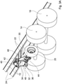
- the invention is shown again from a perspective from the underside of the refrigerated vehicle assembly 2 with the front axle 12 removed. It can be seen that the impeller 20 ends via a semi-axle 26, which is designed as a short stub axle, in a pivoting lever 28 which is pivotable about a pivot axis 30.
- the pivot axis 30 is rotatably mounted in a bracket 32 held by the cross members 22 .
- the holder 32 can be formed from two plates 34 which are arranged parallel to one another in the longitudinal direction and which have 2 receptacles 36 on their underside which accommodate the pivot axis 30 .
- Pivot axis 30 is also connected to a working cylinder 38 which, by changing the length, enables a rotary movement of pivot axis 30, so that impeller 20 can be moved from a resting position in the direction of roadway 18 or back into the resting position.
- Working cylinder 38 can be pneumatic or pneumatic, for example be actuated hydraulically, the use of an electric motor is also conceivable.
- a generator 40 can be seen, which can be connected via a support 42 to the cross members 22 or in other parts of the vehicle frame 10.
- the belt pulley 46 causes the generator 40 to rotate via a second belt 48 . Due to the different diameters on the running surfaces of the first belt 44 and the second belt 48 on the pulley 46, a translation of the rotation of the impeller 20 to the rotation of the generator hub 50 can be achieved.
- FIG figures 4 and 5 now also the central axle 14 and the rear axle 16 are shown removed.
- the figure 5 a side view in the plane AA', which is shown in figure 4 shown by the dashed line.
- the generator 40 can be displaced via the support 42 via a swivel joint 52 and a fuse in a slot 54 with respect to the distance from the pivot axis 30, so that a length compensation can be created, for example, when the refrigerated vehicle arrangement 2 is retrofitted.
- This procedure also allows the generator 40 to be replaced with a more powerful model, for example, which does not necessarily have to have the same external dimensions.
- a belt tensioner 56 can be provided, but this is shown in FIG figure 5 is only drawn in for the first belt 44 .
- the generation of electrical energy can thus be controlled according to the needs of the battery 8. It is particularly advantageous to only use the generator 40 when the refrigerated vehicle is in overrun mode, for example when driving downhill, so that the energy otherwise lost in the braking process can be recuperated.
- the generator 40 can also supply the cooling unit 6 directly with electrical energy without a battery 8 .
- the electrical power output of the generator 40 can also be changed later by replacing the generator 40, with a power output of up to approximately 30 kW typically being able to take place.
Landscapes
- Engineering & Computer Science (AREA)
- Mechanical Engineering (AREA)
- Physics & Mathematics (AREA)
- Thermal Sciences (AREA)
- Transportation (AREA)
- Chemical & Material Sciences (AREA)
- Combustion & Propulsion (AREA)
- Health & Medical Sciences (AREA)
- Public Health (AREA)
- Connection Of Motors, Electrical Generators, Mechanical Devices, And The Like (AREA)
Applications Claiming Priority (1)
| Application Number | Priority Date | Filing Date | Title |
|---|---|---|---|
| DE202020104269.6U DE202020104269U1 (de) | 2020-07-24 | 2020-07-24 | Kühlfahrzeuganordnung und Vorrichtung zum Betrieb eines Generators |
Publications (3)
| Publication Number | Publication Date |
|---|---|
| EP3943330A1 true EP3943330A1 (fr) | 2022-01-26 |
| EP3943330C0 EP3943330C0 (fr) | 2025-03-12 |
| EP3943330B1 EP3943330B1 (fr) | 2025-03-12 |
Family
ID=72660219
Family Applications (1)
| Application Number | Title | Priority Date | Filing Date |
|---|---|---|---|
| EP21186029.1A Active EP3943330B1 (fr) | 2020-07-24 | 2021-07-16 | Système de véhicule frigorifique et dispositif de fonctionnement d'un générateur |
Country Status (2)
| Country | Link |
|---|---|
| EP (1) | EP3943330B1 (fr) |
| DE (1) | DE202020104269U1 (fr) |
Families Citing this family (1)
| Publication number | Priority date | Publication date | Assignee | Title |
|---|---|---|---|---|
| EP4206019A1 (fr) * | 2022-01-04 | 2023-07-05 | Carrier Corporation | Système de réfrigération de transport |
Citations (15)
| Publication number | Priority date | Publication date | Assignee | Title |
|---|---|---|---|---|
| US2584242A (en) * | 1948-01-07 | 1952-02-05 | Tiffany Daniel Warren | Refrigerating system for trailers |
| GB2156291A (en) * | 1984-03-30 | 1985-10-09 | Hubert Ferrier | Regeneration for electrically driven vehicle |
| US5680907A (en) * | 1995-02-17 | 1997-10-28 | Weihe; Clyde R. | Auxiliary solar-power automobile drive system |
| US5921334A (en) * | 1996-12-20 | 1999-07-13 | Al-Dokhi; Mansour Bandar | Highway generator |
| WO2006045124A1 (fr) | 2004-10-21 | 2006-04-27 | Morne Inus Van Rooyen | Vehicule tracte |
| WO2010133863A2 (fr) | 2009-05-18 | 2010-11-25 | Ingineered Limited | Système de génération d'énergie |
| EP2266831A2 (fr) | 2009-06-26 | 2010-12-29 | Green Alternative Solar LLC | Unité de génération d'électricité pour une unité réfrigérateur de véhicule |
| US20120152634A1 (en) | 2010-12-20 | 2012-06-21 | Matthew Skis | Electricity generating in a vehicle by way of a fifth wheel |
| US8439140B1 (en) | 2010-09-01 | 2013-05-14 | Carlos Amortegui | Energy converter assembly |
| US8723344B1 (en) | 2010-06-24 | 2014-05-13 | James Dierickx | Energy harvesting system |
| US20160129753A1 (en) * | 2014-11-06 | 2016-05-12 | Ronald Koelsch | Backup Power Generator For Battery Powered Transport Refrigeration Units |
| US20160347173A1 (en) * | 2015-05-26 | 2016-12-01 | Ronald L. Schafer | Wheel Powered Alternator Charging System |
| US20170144552A1 (en) | 2011-10-20 | 2017-05-25 | Newberry Francis | Range Extending Charging System for an Electric Vehicle |
| EP3205564A2 (fr) * | 2016-01-21 | 2017-08-16 | Herbert Weber | Vélo cargo |
| EP3427992A1 (fr) * | 2017-07-13 | 2019-01-16 | Kiesling Fahrzeugbau GmbH | Véhicule frigorifique |
-
2020
- 2020-07-24 DE DE202020104269.6U patent/DE202020104269U1/de active Active
-
2021
- 2021-07-16 EP EP21186029.1A patent/EP3943330B1/fr active Active
Patent Citations (16)
| Publication number | Priority date | Publication date | Assignee | Title |
|---|---|---|---|---|
| US2584242A (en) * | 1948-01-07 | 1952-02-05 | Tiffany Daniel Warren | Refrigerating system for trailers |
| GB2156291A (en) * | 1984-03-30 | 1985-10-09 | Hubert Ferrier | Regeneration for electrically driven vehicle |
| US5680907A (en) * | 1995-02-17 | 1997-10-28 | Weihe; Clyde R. | Auxiliary solar-power automobile drive system |
| US5921334A (en) * | 1996-12-20 | 1999-07-13 | Al-Dokhi; Mansour Bandar | Highway generator |
| WO2006045124A1 (fr) | 2004-10-21 | 2006-04-27 | Morne Inus Van Rooyen | Vehicule tracte |
| WO2010133863A2 (fr) | 2009-05-18 | 2010-11-25 | Ingineered Limited | Système de génération d'énergie |
| EP2266831A2 (fr) | 2009-06-26 | 2010-12-29 | Green Alternative Solar LLC | Unité de génération d'électricité pour une unité réfrigérateur de véhicule |
| US8723344B1 (en) | 2010-06-24 | 2014-05-13 | James Dierickx | Energy harvesting system |
| US8439140B1 (en) | 2010-09-01 | 2013-05-14 | Carlos Amortegui | Energy converter assembly |
| US20120152634A1 (en) | 2010-12-20 | 2012-06-21 | Matthew Skis | Electricity generating in a vehicle by way of a fifth wheel |
| US20170144552A1 (en) | 2011-10-20 | 2017-05-25 | Newberry Francis | Range Extending Charging System for an Electric Vehicle |
| US20160129753A1 (en) * | 2014-11-06 | 2016-05-12 | Ronald Koelsch | Backup Power Generator For Battery Powered Transport Refrigeration Units |
| US20160347173A1 (en) * | 2015-05-26 | 2016-12-01 | Ronald L. Schafer | Wheel Powered Alternator Charging System |
| EP3205564A2 (fr) * | 2016-01-21 | 2017-08-16 | Herbert Weber | Vélo cargo |
| EP3427992A1 (fr) * | 2017-07-13 | 2019-01-16 | Kiesling Fahrzeugbau GmbH | Véhicule frigorifique |
| DE102017115764A1 (de) | 2017-07-13 | 2019-01-17 | Kiesling Fahrzeugbau Gmbh | Kühlfahrzeug |
Also Published As
| Publication number | Publication date |
|---|---|
| EP3943330C0 (fr) | 2025-03-12 |
| DE202020104269U1 (de) | 2020-09-10 |
| EP3943330B1 (fr) | 2025-03-12 |
Similar Documents
| Publication | Publication Date | Title |
|---|---|---|
| DE102017211314B4 (de) | Betriebsverfahren, Gespann, Kraftfahrzeug und Zugfahrzeug | |
| EP3652002B1 (fr) | Sous-ensemble essieu pour poids-lourd, poids-lourd équipé d'au moins un tel sous-ensemble essieu et arrangement hydraulique, notamment destiné à positionner une unité positionnable réalisée sous la forme d'un arrangement de piston et cylindre | |
| DE102018007825A1 (de) | Verfahren zur Steuerung einer Bodenverdichtungsmaschine und Bodenverdichtungsmaschine | |
| EP3427992B1 (fr) | Véhicule frigorifique | |
| DE1530860A1 (de) | Antriebseinheit fuer ein aus einer einachsigen Zugmaschine und einem einachsigen Anhaenger bestehendes Fahrzeug | |
| EP1918180A1 (fr) | Configuration de véhicule | |
| EP3305633A1 (fr) | Combinaison véhicule couplé-véhicule routier comportant un engin moteur et une remorque en tant que semi-remorque | |
| DE102018006103A1 (de) | Gespann mit einer Sattelzugmaschine und einem Auflieger, Sattelzugmaschine, Auflieger und Verfahren zur Achslastverteilung bei einem Gespann | |
| EP3943330B1 (fr) | Système de véhicule frigorifique et dispositif de fonctionnement d'un générateur | |
| DE69734101T2 (de) | Elektrische Energieaufnahmevorrichtung für Neigezüge | |
| DE102006030347A1 (de) | Lenkbares Anhängerfahrzeug | |
| DE102015103354B4 (de) | Aktive Stabilisatorvorrichtung für ein Fahrzeug | |
| DE102019002655A1 (de) | Achsanordnung für ein Fahrzeug und Fahrzeug mit einer Achsanordnung | |
| EP3771590A1 (fr) | Remorque, véhicule utilitaire et procédé d'accouplement inductif d'un dispositif primaire et d'un dispositif secondaire | |
| EP3469872B1 (fr) | Appareil de travail, véhicule de travail doté d'un tel dispositif de travail, système modulaire de fabrication d'appareil de travail ainsi que procédé de fonctionnement d'au moins l'appareil de travail | |
| DE4441307A1 (de) | Auflieger, Zugmaschine und daraus zusammengesetztes Straßentransportfahrzeug | |
| DE20020953U1 (de) | Untergestell für einen Unterwagen eines fahrbaren Arbeitsgerätes, Fahrwerk und fahrbares Arbeitsgerät | |
| DE102017126682B4 (de) | Arbeitsgerät, Arbeitsfahrzeug mit einem solchen Arbeitsgerät, Baukasten zum Herstellen des Arbeitsgerätes sowie Verfahren zum Betreiben wenigstens des Arbeitsgerätes | |
| DE102021117240B4 (de) | Vorrichtung für eine lenkdeichsel eines anhängers | |
| EP2870843B1 (fr) | Wagon avant d'une remorque à couronne d'orientation | |
| EP2457767B1 (fr) | Chariot de chargement semi-remorque pour le transport ferroviaire de véhicules et procédure de chargement du wagon | |
| DE10333482A1 (de) | Zugfahrzeug für eine Gliederzugkombination | |
| WO2021072468A1 (fr) | Chaîne cinématique et châssis tubulaire central pour un véhicule | |
| DD142169A1 (de) | Anhaengefahrzeug | |
| DE102008062461A1 (de) | Kraftfahrzeug mit Batterie-Anhänger |
Legal Events
| Date | Code | Title | Description |
|---|---|---|---|
| PUAI | Public reference made under article 153(3) epc to a published international application that has entered the european phase |
Free format text: ORIGINAL CODE: 0009012 |
|
| STAA | Information on the status of an ep patent application or granted ep patent |
Free format text: STATUS: THE APPLICATION HAS BEEN PUBLISHED |
|
| AK | Designated contracting states |
Kind code of ref document: A1 Designated state(s): AL AT BE BG CH CY CZ DE DK EE ES FI FR GB GR HR HU IE IS IT LI LT LU LV MC MK MT NL NO PL PT RO RS SE SI SK SM TR |
|
| STAA | Information on the status of an ep patent application or granted ep patent |
Free format text: STATUS: REQUEST FOR EXAMINATION WAS MADE |
|
| 17P | Request for examination filed |
Effective date: 20220726 |
|
| RBV | Designated contracting states (corrected) |
Designated state(s): AL AT BE BG CH CY CZ DE DK EE ES FI FR GB GR HR HU IE IS IT LI LT LU LV MC MK MT NL NO PL PT RO RS SE SI SK SM TR |
|
| GRAP | Despatch of communication of intention to grant a patent |
Free format text: ORIGINAL CODE: EPIDOSNIGR1 |
|
| STAA | Information on the status of an ep patent application or granted ep patent |
Free format text: STATUS: GRANT OF PATENT IS INTENDED |
|
| INTG | Intention to grant announced |
Effective date: 20241108 |
|
| GRAS | Grant fee paid |
Free format text: ORIGINAL CODE: EPIDOSNIGR3 |
|
| GRAA | (expected) grant |
Free format text: ORIGINAL CODE: 0009210 |
|
| STAA | Information on the status of an ep patent application or granted ep patent |
Free format text: STATUS: THE PATENT HAS BEEN GRANTED |
|
| AK | Designated contracting states |
Kind code of ref document: B1 Designated state(s): AL AT BE BG CH CY CZ DE DK EE ES FI FR GB GR HR HU IE IS IT LI LT LU LV MC MK MT NL NO PL PT RO RS SE SI SK SM TR |
|
| REG | Reference to a national code |
Ref country code: GB Ref legal event code: FG4D Free format text: NOT ENGLISH |
|
| REG | Reference to a national code |
Ref country code: CH Ref legal event code: EP |
|
| REG | Reference to a national code |
Ref country code: DE Ref legal event code: R096 Ref document number: 502021006903 Country of ref document: DE |
|
| REG | Reference to a national code |
Ref country code: IE Ref legal event code: FG4D Free format text: LANGUAGE OF EP DOCUMENT: GERMAN |
|
| U01 | Request for unitary effect filed |
Effective date: 20250411 |
|
| U07 | Unitary effect registered |
Designated state(s): AT BE BG DE DK EE FI FR IT LT LU LV MT NL PT RO SE SI Effective date: 20250422 |
|
| PG25 | Lapsed in a contracting state [announced via postgrant information from national office to epo] |
Ref country code: RS Free format text: LAPSE BECAUSE OF FAILURE TO SUBMIT A TRANSLATION OF THE DESCRIPTION OR TO PAY THE FEE WITHIN THE PRESCRIBED TIME-LIMIT Effective date: 20250612 |
|
| PG25 | Lapsed in a contracting state [announced via postgrant information from national office to epo] |
Ref country code: ES Free format text: LAPSE BECAUSE OF FAILURE TO SUBMIT A TRANSLATION OF THE DESCRIPTION OR TO PAY THE FEE WITHIN THE PRESCRIBED TIME-LIMIT Effective date: 20250312 |
|
| PG25 | Lapsed in a contracting state [announced via postgrant information from national office to epo] |
Ref country code: NO Free format text: LAPSE BECAUSE OF FAILURE TO SUBMIT A TRANSLATION OF THE DESCRIPTION OR TO PAY THE FEE WITHIN THE PRESCRIBED TIME-LIMIT Effective date: 20250612 |
|
| PG25 | Lapsed in a contracting state [announced via postgrant information from national office to epo] |
Ref country code: HR Free format text: LAPSE BECAUSE OF FAILURE TO SUBMIT A TRANSLATION OF THE DESCRIPTION OR TO PAY THE FEE WITHIN THE PRESCRIBED TIME-LIMIT Effective date: 20250312 |
|
| PG25 | Lapsed in a contracting state [announced via postgrant information from national office to epo] |
Ref country code: GR Free format text: LAPSE BECAUSE OF FAILURE TO SUBMIT A TRANSLATION OF THE DESCRIPTION OR TO PAY THE FEE WITHIN THE PRESCRIBED TIME-LIMIT Effective date: 20250613 |
|
| U20 | Renewal fee for the european patent with unitary effect paid |
Year of fee payment: 5 Effective date: 20250731 |
|
| PG25 | Lapsed in a contracting state [announced via postgrant information from national office to epo] |
Ref country code: SM Free format text: LAPSE BECAUSE OF FAILURE TO SUBMIT A TRANSLATION OF THE DESCRIPTION OR TO PAY THE FEE WITHIN THE PRESCRIBED TIME-LIMIT Effective date: 20250312 |
|
| PG25 | Lapsed in a contracting state [announced via postgrant information from national office to epo] |
Ref country code: PL Free format text: LAPSE BECAUSE OF FAILURE TO SUBMIT A TRANSLATION OF THE DESCRIPTION OR TO PAY THE FEE WITHIN THE PRESCRIBED TIME-LIMIT Effective date: 20250312 |
|
| PG25 | Lapsed in a contracting state [announced via postgrant information from national office to epo] |
Ref country code: CZ Free format text: LAPSE BECAUSE OF FAILURE TO SUBMIT A TRANSLATION OF THE DESCRIPTION OR TO PAY THE FEE WITHIN THE PRESCRIBED TIME-LIMIT Effective date: 20250312 |
|
| PG25 | Lapsed in a contracting state [announced via postgrant information from national office to epo] |
Ref country code: SK Free format text: LAPSE BECAUSE OF FAILURE TO SUBMIT A TRANSLATION OF THE DESCRIPTION OR TO PAY THE FEE WITHIN THE PRESCRIBED TIME-LIMIT Effective date: 20250312 |
|
| PG25 | Lapsed in a contracting state [announced via postgrant information from national office to epo] |
Ref country code: IS Free format text: LAPSE BECAUSE OF FAILURE TO SUBMIT A TRANSLATION OF THE DESCRIPTION OR TO PAY THE FEE WITHIN THE PRESCRIBED TIME-LIMIT Effective date: 20250712 |
|
| PLBE | No opposition filed within time limit |
Free format text: ORIGINAL CODE: 0009261 |
|
| STAA | Information on the status of an ep patent application or granted ep patent |
Free format text: STATUS: NO OPPOSITION FILED WITHIN TIME LIMIT |
|
| REG | Reference to a national code |
Ref country code: CH Ref legal event code: L10 Free format text: ST27 STATUS EVENT CODE: U-0-0-L10-L00 (AS PROVIDED BY THE NATIONAL OFFICE) Effective date: 20260121 |
|
| 26N | No opposition filed |
Effective date: 20251215 |
|
| REG | Reference to a national code |
Ref country code: CH Ref legal event code: H13 Free format text: ST27 STATUS EVENT CODE: U-0-0-H10-H13 (AS PROVIDED BY THE NATIONAL OFFICE) Effective date: 20260224 |
|
| GBPC | Gb: european patent ceased through non-payment of renewal fee |
Effective date: 20250716 |
|
| PG25 | Lapsed in a contracting state [announced via postgrant information from national office to epo] |
Ref country code: GB Free format text: LAPSE BECAUSE OF NON-PAYMENT OF DUE FEES Effective date: 20250716 |