EP3943457A1 - Procédé et mandrin pour former des formes de verre à rayon de courbure court - Google Patents
Procédé et mandrin pour former des formes de verre à rayon de courbure court Download PDFInfo
- Publication number
- EP3943457A1 EP3943457A1 EP21187481.3A EP21187481A EP3943457A1 EP 3943457 A1 EP3943457 A1 EP 3943457A1 EP 21187481 A EP21187481 A EP 21187481A EP 3943457 A1 EP3943457 A1 EP 3943457A1
- Authority
- EP
- European Patent Office
- Prior art keywords
- glass sheet
- glass
- curvature
- frame
- major surface
- Prior art date
- Legal status (The legal status is an assumption and is not a legal conclusion. Google has not performed a legal analysis and makes no representation as to the accuracy of the status listed.)
- Withdrawn
Links
- 239000011521 glass Substances 0.000 title claims abstract description 350
- 238000000034 method Methods 0.000 title claims abstract description 57
- 125000006850 spacer group Chemical group 0.000 claims description 69
- 239000012790 adhesive layer Substances 0.000 claims description 17
- 239000000463 material Substances 0.000 claims description 8
- 238000005452 bending Methods 0.000 claims description 4
- 239000000203 mixture Substances 0.000 description 42
- 150000002500 ions Chemical class 0.000 description 14
- 239000002585 base Substances 0.000 description 12
- FGIUAXJPYTZDNR-UHFFFAOYSA-N potassium nitrate Chemical compound [K+].[O-][N+]([O-])=O FGIUAXJPYTZDNR-UHFFFAOYSA-N 0.000 description 10
- VWDWKYIASSYTQR-UHFFFAOYSA-N sodium nitrate Chemical compound [Na+].[O-][N+]([O-])=O VWDWKYIASSYTQR-UHFFFAOYSA-N 0.000 description 10
- KKCBUQHMOMHUOY-UHFFFAOYSA-N Na2O Inorganic materials [O-2].[Na+].[Na+] KKCBUQHMOMHUOY-UHFFFAOYSA-N 0.000 description 9
- 230000008569 process Effects 0.000 description 9
- 150000003839 salts Chemical class 0.000 description 9
- 238000007654 immersion Methods 0.000 description 8
- NOTVAPJNGZMVSD-UHFFFAOYSA-N potassium monoxide Inorganic materials [K]O[K] NOTVAPJNGZMVSD-UHFFFAOYSA-N 0.000 description 8
- FUJCRWPEOMXPAD-UHFFFAOYSA-N Li2O Inorganic materials [Li+].[Li+].[O-2] FUJCRWPEOMXPAD-UHFFFAOYSA-N 0.000 description 7
- XUCJHNOBJLKZNU-UHFFFAOYSA-M dilithium;hydroxide Chemical compound [Li+].[Li+].[OH-] XUCJHNOBJLKZNU-UHFFFAOYSA-M 0.000 description 7
- VYPSYNLAJGMNEJ-UHFFFAOYSA-N Silicium dioxide Chemical compound O=[Si]=O VYPSYNLAJGMNEJ-UHFFFAOYSA-N 0.000 description 6
- 239000011248 coating agent Substances 0.000 description 6
- 238000000576 coating method Methods 0.000 description 6
- 238000005342 ion exchange Methods 0.000 description 6
- 238000004381 surface treatment Methods 0.000 description 6
- 229910000272 alkali metal oxide Inorganic materials 0.000 description 5
- GWEVSGVZZGPLCZ-UHFFFAOYSA-N Titan oxide Chemical compound O=[Ti]=O GWEVSGVZZGPLCZ-UHFFFAOYSA-N 0.000 description 4
- -1 alkali metal cations Chemical class 0.000 description 4
- 239000005354 aluminosilicate glass Substances 0.000 description 4
- 229910001414 potassium ion Inorganic materials 0.000 description 4
- 229910001415 sodium ion Inorganic materials 0.000 description 4
- XOLBLPGZBRYERU-UHFFFAOYSA-N tin dioxide Chemical compound O=[Sn]=O XOLBLPGZBRYERU-UHFFFAOYSA-N 0.000 description 4
- 230000007704 transition Effects 0.000 description 4
- KOPBYBDAPCDYFK-UHFFFAOYSA-N Cs2O Inorganic materials [O-2].[Cs+].[Cs+] KOPBYBDAPCDYFK-UHFFFAOYSA-N 0.000 description 3
- 239000003513 alkali Substances 0.000 description 3
- PNEYBMLMFCGWSK-UHFFFAOYSA-N aluminium oxide Inorganic materials [O-2].[O-2].[O-2].[Al+3].[Al+3] PNEYBMLMFCGWSK-UHFFFAOYSA-N 0.000 description 3
- 150000001768 cations Chemical class 0.000 description 3
- 229910052681 coesite Inorganic materials 0.000 description 3
- 229910052593 corundum Inorganic materials 0.000 description 3
- 229910052906 cristobalite Inorganic materials 0.000 description 3
- AKUNKIJLSDQFLS-UHFFFAOYSA-M dicesium;hydroxide Chemical compound [OH-].[Cs+].[Cs+] AKUNKIJLSDQFLS-UHFFFAOYSA-M 0.000 description 3
- 238000005259 measurement Methods 0.000 description 3
- 229910052751 metal Inorganic materials 0.000 description 3
- 239000002184 metal Substances 0.000 description 3
- 230000003287 optical effect Effects 0.000 description 3
- 239000000049 pigment Substances 0.000 description 3
- 229910001953 rubidium(I) oxide Inorganic materials 0.000 description 3
- 239000000377 silicon dioxide Substances 0.000 description 3
- 229910052682 stishovite Inorganic materials 0.000 description 3
- 229910052905 tridymite Inorganic materials 0.000 description 3
- 229910001845 yogo sapphire Inorganic materials 0.000 description 3
- 239000004593 Epoxy Substances 0.000 description 2
- MCMNRKCIXSYSNV-UHFFFAOYSA-N Zirconium dioxide Chemical compound O=[Zr]=O MCMNRKCIXSYSNV-UHFFFAOYSA-N 0.000 description 2
- 229910052783 alkali metal Inorganic materials 0.000 description 2
- 230000008901 benefit Effects 0.000 description 2
- 239000005388 borosilicate glass Substances 0.000 description 2
- 230000008859 change Effects 0.000 description 2
- 238000007796 conventional method Methods 0.000 description 2
- 230000001747 exhibiting effect Effects 0.000 description 2
- 230000009477 glass transition Effects 0.000 description 2
- IIPYXGDZVMZOAP-UHFFFAOYSA-N lithium nitrate Chemical compound [Li+].[O-][N+]([O-])=O IIPYXGDZVMZOAP-UHFFFAOYSA-N 0.000 description 2
- 238000004519 manufacturing process Methods 0.000 description 2
- 238000012986 modification Methods 0.000 description 2
- 230000004048 modification Effects 0.000 description 2
- 150000002823 nitrates Chemical class 0.000 description 2
- 229920000642 polymer Polymers 0.000 description 2
- 239000002861 polymer material Substances 0.000 description 2
- 239000006058 strengthened glass Substances 0.000 description 2
- 238000005728 strengthening Methods 0.000 description 2
- 239000002344 surface layer Substances 0.000 description 2
- 229910000838 Al alloy Inorganic materials 0.000 description 1
- 229910000851 Alloy steel Inorganic materials 0.000 description 1
- DGAQECJNVWCQMB-PUAWFVPOSA-M Ilexoside XXIX Chemical compound C[C@@H]1CC[C@@]2(CC[C@@]3(C(=CC[C@H]4[C@]3(CC[C@@H]5[C@@]4(CC[C@@H](C5(C)C)OS(=O)(=O)[O-])C)C)[C@@H]2[C@]1(C)O)C)C(=O)O[C@H]6[C@@H]([C@H]([C@@H]([C@H](O6)CO)O)O)O.[Na+] DGAQECJNVWCQMB-PUAWFVPOSA-M 0.000 description 1
- ZLMJMSJWJFRBEC-UHFFFAOYSA-N Potassium Chemical compound [K] ZLMJMSJWJFRBEC-UHFFFAOYSA-N 0.000 description 1
- 229920006397 acrylic thermoplastic Polymers 0.000 description 1
- 239000000853 adhesive Substances 0.000 description 1
- 230000001070 adhesive effect Effects 0.000 description 1
- 239000005358 alkali aluminosilicate glass Substances 0.000 description 1
- 229910001413 alkali metal ion Inorganic materials 0.000 description 1
- 229910000287 alkaline earth metal oxide Inorganic materials 0.000 description 1
- XAGFODPZIPBFFR-UHFFFAOYSA-N aluminium Chemical compound [Al] XAGFODPZIPBFFR-UHFFFAOYSA-N 0.000 description 1
- 238000000137 annealing Methods 0.000 description 1
- 239000006117 anti-reflective coating Substances 0.000 description 1
- 239000000919 ceramic Substances 0.000 description 1
- 150000003841 chloride salts Chemical class 0.000 description 1
- 229910052804 chromium Inorganic materials 0.000 description 1
- 238000004891 communication Methods 0.000 description 1
- 239000002131 composite material Substances 0.000 description 1
- 230000006835 compression Effects 0.000 description 1
- 238000007906 compression Methods 0.000 description 1
- 238000010276 construction Methods 0.000 description 1
- 229910052802 copper Inorganic materials 0.000 description 1
- 239000006059 cover glass Substances 0.000 description 1
- 230000007423 decrease Effects 0.000 description 1
- 238000002845 discoloration Methods 0.000 description 1
- 238000009826 distribution Methods 0.000 description 1
- 239000006119 easy-to-clean coating Substances 0.000 description 1
- 229920001971 elastomer Polymers 0.000 description 1
- 239000000835 fiber Substances 0.000 description 1
- 239000005357 flat glass Substances 0.000 description 1
- 239000012530 fluid Substances 0.000 description 1
- 238000010438 heat treatment Methods 0.000 description 1
- 239000012535 impurity Substances 0.000 description 1
- 229910052742 iron Inorganic materials 0.000 description 1
- JEIPFZHSYJVQDO-UHFFFAOYSA-N iron(III) oxide Inorganic materials O=[Fe]O[Fe]=O JEIPFZHSYJVQDO-UHFFFAOYSA-N 0.000 description 1
- 238000005304 joining Methods 0.000 description 1
- 239000010410 layer Substances 0.000 description 1
- 239000010985 leather Substances 0.000 description 1
- 239000004973 liquid crystal related substance Substances 0.000 description 1
- 229910052748 manganese Inorganic materials 0.000 description 1
- 229910052750 molybdenum Inorganic materials 0.000 description 1
- 229910052759 nickel Inorganic materials 0.000 description 1
- 230000003647 oxidation Effects 0.000 description 1
- 238000007254 oxidation reaction Methods 0.000 description 1
- 229920003229 poly(methyl methacrylate) Polymers 0.000 description 1
- 229920001296 polysiloxane Polymers 0.000 description 1
- 229920002635 polyurethane Polymers 0.000 description 1
- 239000004814 polyurethane Substances 0.000 description 1
- 239000011591 potassium Substances 0.000 description 1
- 238000003825 pressing Methods 0.000 description 1
- 238000012545 processing Methods 0.000 description 1
- 238000010791 quenching Methods 0.000 description 1
- 230000000171 quenching effect Effects 0.000 description 1
- 230000005855 radiation Effects 0.000 description 1
- 238000006748 scratching Methods 0.000 description 1
- 230000002393 scratching effect Effects 0.000 description 1
- 239000005368 silicate glass Substances 0.000 description 1
- 239000003707 silyl modified polymer Substances 0.000 description 1
- 239000005361 soda-lime glass Substances 0.000 description 1
- 229910052708 sodium Inorganic materials 0.000 description 1
- 239000011734 sodium Substances 0.000 description 1
- HUAUNKAZQWMVFY-UHFFFAOYSA-M sodium;oxocalcium;hydroxide Chemical compound [OH-].[Na+].[Ca]=O HUAUNKAZQWMVFY-UHFFFAOYSA-M 0.000 description 1
- 238000003892 spreading Methods 0.000 description 1
- 230000007480 spreading Effects 0.000 description 1
- 238000007655 standard test method Methods 0.000 description 1
- 239000000126 substance Substances 0.000 description 1
- 150000003467 sulfuric acid derivatives Chemical class 0.000 description 1
- ISXSCDLOGDJUNJ-UHFFFAOYSA-N tert-butyl prop-2-enoate Chemical compound CC(C)(C)OC(=O)C=C ISXSCDLOGDJUNJ-UHFFFAOYSA-N 0.000 description 1
- 229910052719 titanium Inorganic materials 0.000 description 1
- 238000011282 treatment Methods 0.000 description 1
- 150000003673 urethanes Chemical class 0.000 description 1
- 229910052720 vanadium Inorganic materials 0.000 description 1
- 238000005406 washing Methods 0.000 description 1
- 239000002023 wood Substances 0.000 description 1
Images


Classifications
-
- C—CHEMISTRY; METALLURGY
- C03—GLASS; MINERAL OR SLAG WOOL
- C03B—MANUFACTURE, SHAPING, OR SUPPLEMENTARY PROCESSES
- C03B23/00—Re-forming shaped glass
- C03B23/02—Re-forming glass sheets
- C03B23/023—Re-forming glass sheets by bending
- C03B23/03—Re-forming glass sheets by bending by press-bending between shaping moulds
- C03B23/0305—Press-bending accelerated by applying mechanical forces, e.g. inertia, weights or local forces
-
- C—CHEMISTRY; METALLURGY
- C03—GLASS; MINERAL OR SLAG WOOL
- C03B—MANUFACTURE, SHAPING, OR SUPPLEMENTARY PROCESSES
- C03B23/00—Re-forming shaped glass
- C03B23/0093—Tools and machines specially adapted for re-forming shaped glass articles in general, e.g. chucks
-
- C—CHEMISTRY; METALLURGY
- C03—GLASS; MINERAL OR SLAG WOOL
- C03B—MANUFACTURE, SHAPING, OR SUPPLEMENTARY PROCESSES
- C03B23/00—Re-forming shaped glass
- C03B23/02—Re-forming glass sheets
-
- C—CHEMISTRY; METALLURGY
- C03—GLASS; MINERAL OR SLAG WOOL
- C03B—MANUFACTURE, SHAPING, OR SUPPLEMENTARY PROCESSES
- C03B23/00—Re-forming shaped glass
- C03B23/02—Re-forming glass sheets
- C03B23/023—Re-forming glass sheets by bending
- C03B23/035—Re-forming glass sheets by bending using a gas cushion or by changing gas pressure, e.g. by applying vacuum or blowing for supporting the glass while bending
- C03B23/0352—Re-forming glass sheets by bending using a gas cushion or by changing gas pressure, e.g. by applying vacuum or blowing for supporting the glass while bending by suction or blowing out for providing the deformation force to bend the glass sheet
- C03B23/0357—Re-forming glass sheets by bending using a gas cushion or by changing gas pressure, e.g. by applying vacuum or blowing for supporting the glass while bending by suction or blowing out for providing the deformation force to bend the glass sheet by suction without blowing, e.g. with vacuum or by venturi effect
-
- C—CHEMISTRY; METALLURGY
- C03—GLASS; MINERAL OR SLAG WOOL
- C03C—CHEMICAL COMPOSITION OF GLASSES, GLAZES OR VITREOUS ENAMELS; SURFACE TREATMENT OF GLASS; SURFACE TREATMENT OF FIBRES OR FILAMENTS MADE FROM GLASS, MINERALS OR SLAGS; JOINING GLASS TO GLASS OR OTHER MATERIALS
- C03C27/00—Joining pieces of glass to pieces of other inorganic material; Joining glass to glass other than by fusing
- C03C27/06—Joining glass to glass by processes other than fusing
- C03C27/10—Joining glass to glass by processes other than fusing with the aid of adhesive specially adapted for that purpose
-
- G—PHYSICS
- G02—OPTICS
- G02F—OPTICAL DEVICES OR ARRANGEMENTS FOR THE CONTROL OF LIGHT BY MODIFICATION OF THE OPTICAL PROPERTIES OF THE MEDIA OF THE ELEMENTS INVOLVED THEREIN; NON-LINEAR OPTICS; FREQUENCY-CHANGING OF LIGHT; OPTICAL LOGIC ELEMENTS; OPTICAL ANALOGUE/DIGITAL CONVERTERS
- G02F1/00—Devices or arrangements for the control of the intensity, colour, phase, polarisation or direction of light arriving from an independent light source, e.g. switching, gating or modulating; Non-linear optics
- G02F1/01—Devices or arrangements for the control of the intensity, colour, phase, polarisation or direction of light arriving from an independent light source, e.g. switching, gating or modulating; Non-linear optics for the control of the intensity, phase, polarisation or colour
- G02F1/13—Devices or arrangements for the control of the intensity, colour, phase, polarisation or direction of light arriving from an independent light source, e.g. switching, gating or modulating; Non-linear optics for the control of the intensity, phase, polarisation or colour based on liquid crystals, e.g. single liquid crystal display cells
- G02F1/133—Constructional arrangements; Operation of liquid crystal cells; Circuit arrangements
- G02F1/1333—Constructional arrangements; Manufacturing methods
- G02F1/133308—Support structures for LCD panels, e.g. frames or bezels
- G02F1/13332—Front frames
-
- G—PHYSICS
- G02—OPTICS
- G02F—OPTICAL DEVICES OR ARRANGEMENTS FOR THE CONTROL OF LIGHT BY MODIFICATION OF THE OPTICAL PROPERTIES OF THE MEDIA OF THE ELEMENTS INVOLVED THEREIN; NON-LINEAR OPTICS; FREQUENCY-CHANGING OF LIGHT; OPTICAL LOGIC ELEMENTS; OPTICAL ANALOGUE/DIGITAL CONVERTERS
- G02F2201/00—Constructional arrangements not provided for in groups G02F1/00 - G02F7/00
- G02F2201/46—Fixing elements
Definitions
- the disclosure relates to a method of forming a curved glass article and, more particularly, to a method of forming a curved glass article having a tight bend radius and small shape deviation.
- Vehicle interiors include curved surfaces and can incorporate displays in such curved surfaces.
- the materials used to form such curved surfaces are typically limited to polymers, which do not exhibit the durability and optical performance as glass.
- curved glass sheets are desirable, especially when used as covers for displays.
- Existing methods of forming such curved glass sheets, such as thermal forming have drawbacks including high cost, optical distortion, and surface marking.
- several forming apparatuses are needed for each processing line, and because of the number of forming apparatuses needed, the forming apparatuses are preferably relatively inexpensive to manufacture and use. Accordingly, Applicant has identified a need for vehicle interior systems that can incorporate a curved glass sheet in a cost-effective manner and without problems typically associated with glass thermal forming processes.
- embodiments of the disclosure relate to a method of forming a glass article.
- a glass sheet is bent over a forming surface of a chuck.
- the forming surface defines a first shape including a first curvature having a first radius of curvature of 1000 mm or less, and the glass sheet includes a first major surface in contact with the forming surface and a second major surface opposite to the first major surface.
- a frame is adhered to the second major surface of the glass sheet.
- the frame includes a frame support surface defining a second shape including a second curvature having a second radius of curvature of 1000 mm or less.
- a total force is applied to the glass sheet so that the glass sheet forms a third shape including a third curvature having a third radius of curvature of 1000 mm or less.
- the third shape deviates from the second shape by 2 mm or less across the frame support surface.
- inventions of the disclosure relate to a system for forming a glass article.
- the glass article includes a glass sheet adhered to a frame.
- the system includes a chuck with a forming surface including a first curvature having a first radius of curvature of 1000 mm or less.
- the system also includes at least one retainer configured to apply a first force to the glass sheet to hold the glass sheet against the forming surface.
- inventions of the disclosure relate to a system for forming a glass article.
- the glass article includes a glass sheet adhered to a frame.
- the system includes a chuck with a forming surface including a first curvature having a first radius of curvature of 1000 mm or less.
- the system also includes a clamping cover configured to hold the frame.
- the clamping cover includes a spacer disposed adjacent to the frame. The spacer applies a first force to the glass sheet during forming of the glass article.
- inventions of the disclosure relate to a glass article.
- the glass article includes a glass sheet having a first major surface and a second major surface opposite to the first major surface.
- the second major surface defines a first shape including a first curvature having a first radius of curvature of 250 mm or less.
- the glass article also includes a frame adhered to the second major surface of the glass sheet.
- the frame has a frame support surface defining a second shape comprising a second curvature having a second radius of curvature of 250 mm or less.
- the first shape deviates from the second shape by 0.2 mm or less across the frame support surface.
- the present disclosure is directed to a method and system for cold-forming a glass article having a tight bend radius (e.g., ⁇ 1000 mm, in particular ⁇ 250 mm) in such a manner that the shape deviation is within an acceptable tolerance threshold (e.g., 2.0 mm or less, in particular 0.2 mm or less).
- a tight bend radius e.g., ⁇ 1000 mm, in particular ⁇ 250 mm
- an acceptable tolerance threshold e.g. 2.0 mm or less, in particular 0.2 mm or less.
- embodiments of the present disclosure provide ways to increase the forces on the glass sheet during forming, using spacers and retainers, so that the shape deviation of the glass article from the tight curvatures is reduced to acceptable tolerances or eliminated entirely. Additionally, the mechanical forces are applied in such a way and in particular locations designed to effectively address the issue of shape deviation during cold forming.
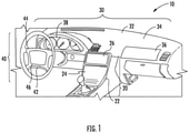
- FIG. 1 shows an exemplary interior 10 of a vehicle that includes three different embodiments of vehicle interior systems 20, 30, 40.
- Vehicle interior system 20 includes a base, shown as center console base 22, with a curved surface 24 including a display 26.
- Vehicle interior system 30 includes a base, shown as dashboard base 32, with a curved surface 34 including a display 36.
- the dashboard base 32 typically includes an instrument panel 38 which may also include a display.
- Vehicle interior system 40 includes a base, shown as steering wheel base 42, with a curved surface 44 and a display 46.
- the vehicle interior system includes a base that is an arm rest, a pillar, a seat back, a floor board, a headrest, a door panel, or any portion of the interior of a vehicle that includes a curved surface.
- the embodiments of the curved glass articles described herein can be used in each of vehicle interior systems 20, 30, 40, among others.
- the glass article discussed herein may include a cover glass sheet that also covers non-display surfaces of the dashboard, center console, steering wheel, door panel, etc.
- the glass material may be selected based on its weight, aesthetic appearance, etc. and may be provided with a coating (e.g., an ink or pigment coating) including a pattern (e.g., a brushed metal appearance, a wood grain appearance, a leather appearance, a colored appearance, etc.) to visually match the glass components with adjacent non-glass components.
- a coating e.g., an ink or pigment coating
- a pattern e.g., a brushed metal appearance, a wood grain appearance, a leather appearance, a colored appearance, etc.
- such ink or pigment coating may have a transparency level that provides for deadfront or color matching functionality when the display 26, 36, 38, 46 is inactive.
- vehicle interior of FIG. 1 depicts a vehicle in the form of an automobile (e.g., cars, trucks, buses and the like)
- the glass articles disclosed herein can be incorporated into other vehicles, such as trains, sea craft (boats, ships, submarines, and the like), and aircraft (e.g., drones, airplanes, jets, helicopters and the like).
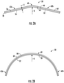
- the curved surfaces 24, 34, 44 can be any of a variety of curved shapes, such as V-shaped or C-shaped curved glass articles as shown in FIGS. 2A and 2B , respectively.
- FIG. 2A a side view of an embodiment of a V-shaped glass article 50 is shown.
- the glass article 50 includes a glass sheet 52 having a first major surface 54, a second major surface 56 opposite to the first major surface 54, and a minor surface 58 joining the first major surface 54 to the second major surface 56.
- the first major surface 54 and the second major surface 56 define a thickness T of the glass sheet 52.
- the thickness T of the glass sheet 52 is from 0.3 mm to 2 mm, in particular 0.5 mm to 1.1 mm.
- the first major surface 54 faces the occupants of the vehicle.
- the second major surface 56 may have a display module (e.g., display 26, 36, 38, 46 of FIG. 1 ) mounted thereon, such as a light-emitting diode (LED) display, an organic LED (OLED) display, a micro-LED display, a liquid crystal display (LCD), or a plasma display.
- a display module e.g., display 26, 36, 38, 46 of FIG. 1
- LED light-emitting diode
- OLED organic LED
- micro-LED micro-LED
- LCD liquid crystal display
- the first major surface 54 and/or the second major surface 56 includes one or more surface treatments.
- surface treatments that may be applied to one or both of the first major surface 54 and second major surface 56 include an anti-glare coating, an anti-reflective coating, a coating providing touch functionality, a decorative (e.g., ink or pigment) coating, and an easy-to-clean coating.
- the glass sheet 52 has a curved region 60 disposed between a first flat section 62a and a second flat section 62b.
- the forming methods and system are particularly suitable for forming a curved region 60 having a radius of curvature R that is 1000 mm or less, in particular 250 mm or less.
- the curved region 60 defines a concave curve with respect to the first major surface 54, but in other embodiments, the curved region 60 is instead a convex curve with respect to the first major surface 54.
- a frame 64 is adhered to the second major surface 56 of the glass sheet 52 using an adhesive layer 66.
- the adhesive layer 66 is a structural adhesive, such toughened epoxy, flexible epoxy, acrylics, silicones, urethanes, polyurethanes, and silane modified polymers.
- the adhesive layer 66 has a thickness of 2 mm or less between the frame 64 and the glass sheet 52.
- the frame 64 facilitates mounting the glass article 50 to a vehicle interior base (such as center console base 22, dashboard base 32, and/or steering wheel base 42 as shown in FIG. 1 ).
- the frame 64 has a curved frame support surface 65 that holds the glass sheet 52 in its curved shape (at least in the curved region 60).
- the glass sheet 52 is formed in such a way that the curved region 60 is not permanent. That is, the glass sheet 52 would spring back to a planar, non-curved configuration if the glass sheet 52 was not adhered to the frame 64 using the adhesive layer 66.
- the glass sheet 52 is stressed to produce the curvature and remains stressed during the life of the glass article 50. In this way, maintaining the desired curvature, especially at tight bend radiuses, is important during forming of the curved glass article 50.
- FIG. 2B depicts another embodiment of a glass article 50, in particular a C-shaped glass article 50.
- the C-shaped glass article 50 of FIG. 2B has a larger curved region 60 and shorter flat sections 62a, 62b.
- the V-shape and C-shape are but two examples of curved glass articles 50 that can be created according to the present disclosure.
- the glass articles 50 can include curved regions 60 having opposing curvatures to create an S-shape, a curved region 60 followed by a flat section 62a to create a J-shape, and curved regions 60 separated by a flat section 62a to create a U-shape, among others.
- the glass articles 50 according to the present disclosure are formed by cold-forming techniques.
- the process of cold-forming involves application of a bending force to the glass sheet 52 while the glass sheet 52 is situated on a chuck 68 as shown in the exploded view of FIG. 3 .
- the chuck 68 has a curved forming surface 70, and the glass sheet 52 is bent into conformity with the curved forming surface 70.
- the cold forming process is performed at a temperature less than the glass transition temperature of the glass sheet 52.
- the cold forming process may be performed at room temperature (e.g., about 20 °C) or a slightly elevated temperature, e.g., at 200 °C or less, 150 °C or less, 100 °C or less, or at 50 °C or less.
- the bending force applied to the glass sheet 52 is, in part, in the form of vacuum pressure pulled through the chuck 68.
- the chuck 68 includes one or more sets of surface channels 72. Each set of surface channels 72 is in fluid communication with a vacuum conduit 74 that extend transversely across its respective set of surface channels 72. In this way, vacuum can be pulled through each set of the surface channels 72 from the respective vacuum conduit 74 fluidly connecting them.
- This vacuum pressure holds the glass sheet 52 against the chuck and in conformity with the curvature of the forming surface 70.
- the vacuum pressure may be pulled through a plurality of ports on the forming surface 70.
- the glass sheet When the glass sheet is bent over the forming surface of the chuck, the glass sheet can deflect from the desired curvature despite the vacuum pressure holding the glass sheet 52 into contact with the curved forming surface.
- the desired curvature is defined by either the curvature of the forming surface or the curvature of the frame support surface.
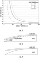
- shape deviation refers to the deflection of the glass sheet from the desired curvature. As the radius of curvature decreases (i.e., at a tighter bend radius), the glass sheet will tend to deflect more as shown in FIG. 5 . Further, thicker glass sheets will deflect more than relatively thinner glass sheets at the same radius of curvature.
- a glass sheet having a thickness of 0.7 mm may have a shape deviation of about 0.2 mm whereas a glass sheet having a thickness of 1.1 mm may have a shape deviation of about 0.8 mm and a glass sheet having a thickness of 1.3 mm may have a shape deviation of about 1.3 mm.
- the deflection increases rapidly at curvatures below 250 mm for each glass thickness shown.
- FIG. 6 depicts a glass sheet in contact with a forming surface of a chuck.
- the vacuum channels generally hold the glass sheet into contact with the forming surface except at an end region of the chuck.
- the end region includes a gasket designed to maintain the vacuum seal with the glass sheet, but the vacuum pressure alone is not sufficient to compress the gasket so as to completely eliminate deflection from the desired curvature (which, in this case, is defined by the curvature of the forming surface).
- the maximum vacuum force that can be applied to the glass sheet is the atmospheric pressure multiplied by the surface area of the second major surface of the glass sheet.
- FIG. 7 depicts a shape deviation of the glass sheet from the forming surface of a chuck that does not include a vacuum feature.
- Shape deviation such an instance may be the result of, for example, uneven pressure applied to the glass sheet during cold-forming or using a glass sheet too thick for the curvature.
- FIG. 8 depicts shape deviation from desired curvature across the first major surface of a glass sheet having a thickness of 0.7 mm cold-bent to a radius of curvature of 208 mm using conventional techniques. As can be seen, shape deviation can be as high as about 1 mm at end regions of the glass sheet using conventional cold-forming techniques.
- various methods of cold-forming a glass sheet to mitigate such shape deviation to an acceptable tolerance e.g., 0.2 mm or less
- an acceptable tolerance e.g., 0.2 mm or less
- a total force is applied to the glass sheet to hold it in compliance with the forming surface in which the total force is greater than the surface area of the glass sheet in contact with the forming surface multiplied by atmospheric pressure.
- the frame 64 may be positioned over the glass sheet 52 on the chuck 68 using a robotic positioning arm 80 as shown in FIG. 9 .
- the robotic positioning arm 80 carries a clamping cover 82 that carries the frame 64.
- the robotic positioning arm 80 is connected to a force distribution plate 84 that spreads the force of the robotic arm 80 over the clamping cover 82.
- positioning guides 86 interact with alignment features 88 of the clamping cover 82 to position the frame 64 over the glass sheet 52. In this way, the glass article 50 can be assembled accurately and in an automated manner.
- the robotic positioning arm 80 may pick up a frame 64 using the clamping cover 82.
- the robotic positioning arm 80 then places the frame 64 over the glass sheet 52 on the chuck 68.
- the adhesive layer 66 (not shown) is applied to either the frame 64 or glass sheet 52 or to both.
- the robotic positioning arm 80 then pushes the frame 64 onto the glass sheet 52, spreading the adhesive layer 66 to achieve a consistent bondline thickness.
- the robotic positioning arm 80 holds the frame 64 over the glass sheet 52 until the adhesive layer 66 has cured sufficiently that the glass sheet 52 will not deviate from the desired cold-formed shape.
- FIGS. 10A-10C depict an embodiment in which shape deviation is minimized using a spacer 90.
- the spacer 90 may be positioned on the frame support surface 65 ( FIG. 10A ) or the second major surface 56 of the glass sheet 52 ( FIG. 10B ).
- the spacer 90 is a component that applies mechanical force to the glass sheet 52 during cold forming when the frame 64 is pressed onto the glass sheet 52.
- the spacer 90 is positioned adjacent to the adhesive layer 66 between the frame 64 and the glass sheet 52 and allows mechanical forces imparted, e.g., by the robotic positioning arm 80 to be transferred through the frame 64 to the glass sheet 52 so as to keep the glass sheet 52 in conformity with the forming surface 70 of the chuck 68.
- the spacer 90 is a rigid metal, ceramic, polymer, or composite material that does not compress substantially when force is applied by the robotic positioning arm 80 through the frame 64.
- the spacer 90 is made of a compliant material, such as rubber, but the spacer 90 still transfers force, e.g., from the positioning arm 80 through the frame 64 to the glass sheet 52.
- the chuck 68 is depicted as a vacuum chuck having vacuum channels 72 through which vacuum is pulled to keep the first major surface 54 of the glass sheet 52 in conformity with the curvature of the forming surface 70.
- the robotic positioning arm 80 would not be able to exert substantial force on the glass sheet 52 without causing the adhesive layer 66 to seep out between the frame 64 and glass sheet 52.
- the spacer 90 forces from the robotic positioning arm 80 can be imparted to the glass sheet 52, especially in edge regions where shape deviation is greatest, to prevent or limit such shape deviation.
- the mechanical force imparted through the spacer 90 allows additional force to compress an edge gasket 91 shown in FIG. 10C , providing better conformity with the desired curvature defined by the forming surface 70 of the chuck 68.
- the spacer 90 defines the adhesive layer 66 thickness in the final cold-formed glass article 50.
- FIGS. 11A-11F depict a variety of different embodiments of a spacer 90.
- the spacer 90 is placed inside the bondline of the adhesive layer 66 (as compared to outside the bondline as shown in in FIG. 10C ).
- FIG. 11B depicts an embodiment in which the spacer 90 is a projection of the frame support surface 65. That is, the spacer 90 may be, in embodiments, part of a unitary construction with the frame 64.
- the frame 64 is generally made of a rigid material, such as a metal (e.g., aluminum or steel alloy), which might otherwise scratch the glass sheet 52.
- the spacer 90 may be coated with a buffer material 93, such as a polymer material, to prevent scratching of the glass sheet 52.
- the spacer 90 is clipped onto the interior of the frame 64.
- the spacer 90 includes a vertical arm 92 having a horizontal projection 94 configured to engage a slot 96 on the interior of the frame 64.
- the mechanical projection 94 and slot 96 may be a snaplock engagement or slidable arrangement.
- the spacer 90 is clipped to the exterior of the frame 64.
- the spacer includes a vertical arm 92 having a horizontal projection 94 configured to engage a slot 96 on the exterior of the frame 64.
- FIG. 11E depicts another embodiment of the spacer 90 in which the spacer 90 is temporarily attached to the exterior of the frame 64 using a fastener 98 (such as a screw or pin).
- the spacer 90 includes a vertical arm 92 including an aperture 100 through which the fastener 98 is inserted to connect the spacer 90 to the frame 64.
- the fastener 98 can be removed so that the spacer 90 can be removed from the finished glass article 52.
- FIG. 11F depicts another embodiment of the spacer 90 that engages the first major surface 54 of the glass sheet 52.
- the support surface 65 of the frame 64 defines the desired curvature of the glass article 52.
- the spacer 90 pulls the glass sheet 52 into conformity with the support surface 65.
- the spacer 90 includes a vertical arm 92 and a horizontal arm 102.
- the vertical arm 92 extends along the exterior of the frame 64 and includes an aperture 100 through which a fastener 98 is inserted to engage the frame 64.
- the horizontal arm 102 extends under the glass sheet 52 to engage the first major surface 54 of the glass sheet 52. In this way, the spacer 90 pulls the glass sheet 52 into the shape defined by the frame support surface 65 or prevents the glass sheet 52 from deflecting out of the desired shape.
- FIGS. 12A-12C depict positions where the spacers 90 may be used to maintain the desired shape of the glass sheet 52.
- the spacers 90 are located at the edges of the curved region 60 of the glass article 52.
- the spacers 90 are positioned towards the interior of the glass article 52 where the curved region 60 transitions to the flat sections 62a, 62b.
- the spacers 90 may be located toward the edges of the glass article 52.
- the curved region 60 of a C-shaped glass article 52 is more extensive than in a V-shaped glass article 52, and thus, the flat sections 62a, 62b are smaller. Notwithstanding, the spacers 90 would still be positioned proximate to where the curved region 60 transitions to the flat sections 62a, 62b. Further, as show in FIG. 12C , the spacers 90, in embodiments, do not extend continuously along the transition between curved region 60 and flat section 62a, 62b. Instead, the spacers 90 may be intermittently positioned along the transition between curved region 60 and flat sections 62a, 62b.
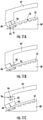
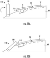
- FIGS. 13A-13B , FIGS. 14A-14B and FIGS. 15A-15B depict various embodiments of retainers 110 incorporated with the chuck 68.
- FIG. 13A depicts a retainer 110 that slides laterally over the forming surface 70 to hold down an edge 112 of the glass sheet 52 to maintain conformity of the glass sheet 52 with the forming surface 70.
- the retainer 110 includes an angled retaining surface 114. When the glass sheet 52 is cold-bent over the forming surface 70, the retainer 110 is slid into place as shown in FIG. 13B such that the angled retaining surface 114 applies an increasing mechanical force to the edge 112 of the glass sheet 52 that is sufficient to compress the gasket 91.
- the retainer 110 may simply hold the edge 112 of the glass sheet 52 in conformity with the forming surface 70 even in the absence of a gasket 91, such as for example if the thickness of the glass sheet 52 tends to cause the glass sheet 52 to deflect away from the forming surface 70.
- FIG. 14A depicts another embodiment of a retainer 110 that swivels in order to apply a mechanical force to the edge 112 of the glass sheet 52.
- the retainer 110 includes a post 116 having a ramped surface 118 projecting radially from the post.
- the post 116 is rotated so that the ramped surface 118 exerts a force over the second major surface 54 of the glass sheet 52 that increases as the post 116 swivels.
- the retainer 110 maintains the glass sheet 52 in conformity with the forming surface 70 of the chuck 68 as shown in FIG. 14B .
- FIG. 15A depicts still another embodiment of a retainer 110 having a rotating arm 120.
- the rotating arm 120 When the glass sheet 52 is initially cold-bent over the forming surface 70, the rotating arm 120 is in a first position depicted as vertical in FIG. 15A . Thereafter, the rotating arm 120 is rotated so that it contacts the second major surface 54 of the glass sheet 52 as shown in FIG. 15B . When rotated into contact with the glass sheet 52, the rotating arm 120 exerts a force on the edge 112 glass sheet 52 that keeps the glass sheet 52 in conformity with the forming surface 70 of the chuck 68.
- the retainer 110 may be spring actuated or electro-mechanically actuated using, e.g., a servomotor. Further still, the foregoing embodiments of the retainers 110 may be actuated manually by a user.
- FIGS. 16A and 16B depict an embodiment in which the clamping cover 82 includes a spacer 90.
- the glass sheet 52 is cold bent over the forming surface 70 of the chuck 68.
- the adhesive layer 66 is applied to the second major surface 56, and the clamping cover 82 lowers the frame 64 over the glass sheet 52.
- the spacer 90 engages the second major surface 56 of the glass sheet 52, applying a mechanical force to an edge 112 of the glass sheet 52 to place the glass sheet 52 into conformity with the forming surface 70 of the chuck 68.
- the clamping cover 82 is withdrawn such that the finished glass article 50 does not incorporate the spacer 90.
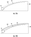
- FIG. 17A and 17B depict an embodiment in which the chuck 68 is designed such that the forming surface 70 does not define the desired curvature of the glass article 50. Instead, as shown by the dashed line 122, the curvature takes into account the expected deflection of the glass sheet 52 from the forming surface 70, e.g., as a result of a perimeter gasket 91. In this way, the chuck 68 is provided with a forming surface 70 having a curvature that is deliberately smaller than the desired final curvature of the glass article 50.
- glass sheet 52 has a thickness T that is substantially constant and is defined as a distance between the first major surface 54 and the second major surface 56.
- T may refer to an average thickness or a maximum thickness of the glass sheet.
- glass sheet 52 includes a width W defined as a first maximum dimension of one of the first or second major surfaces 54, 56 orthogonal to the thickness T, and a length L defined as a second maximum dimension of one of the first or second major surfaces 54, 56 orthogonal to both the thickness and the width.
- W and L may be the average width and the average length of glass sheet 52, respectively.
- average or maximum thickness T is in the range of 0.3 mm to 2 mm.
- width W is in a range from 5 cm to 250 cm
- length L is in a range from about 5 cm to about 1500 cm.
- the radius of curvature (e.g., R as shown in FIGS. 2A and 2B ) of glass sheet 52 is about 30 mm to about 1000 mm.
- the glass sheet 52 may be strengthened.
- glass sheet 52 may be strengthened to include compressive stress that extends from a surface to a depth of compression (DOC).
- DOC depth of compression
- the compressive stress regions are balanced by a central portion exhibiting a tensile stress.
- the stress crosses from a positive (compressive) stress to a negative (tensile) stress.
- glass sheet 52 may be strengthened mechanically by utilizing a mismatch of the coefficient of thermal expansion between portions of the article to create a compressive stress region and a central region exhibiting a tensile stress.
- the glass sheet may be strengthened thermally by heating the glass to a temperature above the glass transition point and then rapidly quenching.
- glass sheet 52 may be chemically strengthened by ion exchange.
- ions at or near the surface of the glass sheet are replaced by - or exchanged with - larger ions having the same valence or oxidation state.
- ions in the surface layer of the article and the larger ions are monovalent alkali metal cations, such as Li + , Na + , K + , Rb + , and Cs + .
- monovalent cations in the surface layer may be replaced with monovalent cations other than alkali metal cations, such as Ag + or the like.
- the monovalent ions (or cations) exchanged into the glass sheet generate a stress.
- Ion exchange processes are typically carried out by immersing a glass sheet in a molten salt bath (or two or more molten salt baths) containing the larger ions to be exchanged with the smaller ions in the glass sheet.
- a molten salt bath or two or more molten salt baths
- aqueous salt baths may also be utilized.
- the composition of the bath(s) may include more than one type of larger ions (e.g., Na+ and K+) or a single larger ion.
- parameters for the ion exchange process including, but not limited to, bath composition and temperature, immersion time, the number of immersions of the glass sheet in a salt bath (or baths), use of multiple salt baths, additional steps such as annealing, washing, and the like, are generally determined by the composition of the glass sheet (including the structure of the article and any crystalline phases present) and the desired DOC and CS of the glass sheet that results from strengthening.
- Exemplary molten bath compositions may include nitrates, sulfates, and chlorides of the larger alkali metal ion. Typical nitrates include KNO 3 , NaNO 3 , LiNO 3 , NaSO 4 and combinations thereof.
- the temperature of the molten salt bath typically is in a range from about 380°C up to about 450°C, while immersion times range from about 15 minutes up to about 100 hours depending on glass sheet thickness, bath temperature and glass (or monovalent ion) diffusivity. However, temperatures and immersion times different from those described above may also be used.
- the glass sheet 52 may be immersed in a molten salt bath of 100% NaNO 3 , 100% KNO 3 , or a combination of NaNO 3 and KNO 3 having a temperature from about 370 °C to about 480 °C.
- the glass sheet may be immersed in a molten mixed salt bath including from about 5% to about 90% KNO 3 and from about 10% to about 95% NaNO 3 .
- the glass sheet may be immersed in a second bath, after immersion in a first bath.
- the first and second baths may have different compositions and/or temperatures from one another. The immersion times in the first and second baths may vary. For example, immersion in the first bath may be longer than the immersion in the second bath.
- the glass sheet may be immersed in a molten, mixed salt bath including NaNO 3 and KNO 3 (e.g., 49%/51%, 50%/50%, 51%/49%) having a temperature less than about 420 °C (e.g., about 400 °C or about 380 °C). for less than about 5 hours, or even about 4 hours or less.
- a molten, mixed salt bath including NaNO 3 and KNO 3 (e.g., 49%/51%, 50%/50%, 51%/49%) having a temperature less than about 420 °C (e.g., about 400 °C or about 380 °C). for less than about 5 hours, or even about 4 hours or less.
- Ion exchange conditions can be tailored to provide a "spike” or to increase the slope of the stress profile at or near the surface of the resulting glass sheet.
- the spike may result in a greater surface CS value.
- This spike can be achieved by a single bath or multiple baths, with the bath(s) having a single composition or mixed composition, due to the unique properties of the glass compositions used in the glass sheets described herein.
- the different monovalent ions may exchange to different depths within the glass sheet (and generate different magnitudes stresses within the glass sheet at different depths).
- the resulting relative depths of the stress-generating ions can be determined and cause different characteristics of the stress profile.
- CS is measured using those means known in the art, such as by surface stress meter (FSM) using commercially available instruments such as the FSM-6000, manufactured by Orihara Industrial Co., Ltd. (Japan).
- FSM surface stress meter
- FSM-6000 manufactured by Orihara Industrial Co., Ltd. (Japan).
- SOC stress optical coefficient
- ASTM standard C770-98 (2013) entitled “Standard Test Method for Measurement of Glass Stress-Optical Coefficient ,” the contents of which are incorporated herein by reference in their entirety, and a bulk cylinder method.
- CS may be the "maximum compressive stress" which is the highest compressive stress value measured within the compressive stress layer.
- the maximum compressive stress is located at the surface of the glass sheet. In other embodiments, the maximum compressive stress may occur at a depth below the surface, giving the compressive profile the appearance of a "buried peak.”
- DOC may be measured by FSM or by a scattered light polariscope (SCALP) (such as the SCALP-04 scattered light polariscope available from Glasstress Ltd., located in Tallinn Estonia), depending on the strengthening method and conditions.
- SCALP scattered light polariscope
- FSM or SCALP may be used depending on which ion is exchanged into the glass sheet.
- FSM is used to measure DOC.
- SCALP is used to measure DOC.
- the DOC is measured by SCALP, since it is believed the exchange depth of sodium indicates the DOC and the exchange depth of potassium ions indicates a change in the magnitude of the compressive stress (but not the change in stress from compressive to tensile); the exchange depth of potassium ions in such glass sheets is measured by FSM.
- Central tension or CT is the maximum tensile stress and is measured by SCALP.
- the glass sheet may be strengthened to exhibit a DOC that is described as a fraction of the thickness T of the glass sheet (as described herein).
- the DOC may be in the range of about 0.05T to about 0.25T. In some instances, the DOC may be in the range of about 20 ⁇ m to about 300 ⁇ m.
- the strengthened glass sheet 52 may have a CS (which may be found at the surface or a depth within the glass sheet) of about 200 MPa or greater, about 500 MPa or greater, or about 1050 MPa or greater.
- the strengthened glass sheet may have a maximum tensile stress or central tension (CT) in the range of about 20 MPa to about 100 MPa.
- CT maximum tensile stress or central tension
- Suitable glass compositions for use as glass sheet 52 include soda lime glass, aluminosilicate glass, borosilicate glass, boroaluminosilicate glass, alkali-containing aluminosilicate glass, alkali-containing borosilicate glass, and alkali-containing boroaluminosilicate glass.
- the glass compositions disclosed herein are described in mole percent (mol%) as analyzed on an oxide basis.
- the glass composition may include SiO 2 in an amount in a range from about 66 mol% to about 80 mol%. In one or more embodiments, the glass composition includes Al 2 O 3 in an amount of about 3 mol% to about 15 mol%. In one or more embodiments, the glass article is described as an aluminosilicate glass article or including an aluminosilicate glass composition. In such embodiments, the glass composition or article formed therefrom includes SiO 2 and Al 2 O 3 and is not a soda lime silicate glass.
- the glass composition comprises B 2 O 3 in an amount in the range of about 0.01 mol% to about 5 mol%. However, in one or more embodiments, the glass composition is substantially free of B 2 O 3 . As used herein, the phrase "substantially free" with respect to the components of the composition means that the component is not actively or intentionally added to the composition during initial batching, but may be present as an impurity in an amount less than about 0.001 mol%.
- the glass composition optionally comprises P 2 O 5 in an amount of about 0.01 mol% to 2 mol%. In one or more embodiments, the glass composition is substantially free of P 2 O 5 .
- the glass composition may include a total amount of R 2 O (which is the total amount of alkali metal oxide such as Li 2 O, Na 2 O, K 2 O, Rb 2 O, and Cs 2 O) that is in a range from about 8 mol% to about 20 mol%.
- the glass composition may be substantially free of Rb 2 O, Cs 2 O or both Rb 2 O and Cs 2 O.
- the R 2 O may include the total amount of Li 2 O, Na 2 O and K 2 O only.
- the glass composition may comprise at least one alkali metal oxide selected from Li 2 O, Na 2 O and K 2 O, wherein the alkali metal oxide is present in an amount greater than about 8 mol% or greater.
- the glass composition comprises Na 2 O in an amount in a range from about from about 8 mol% to about 20 mol%. In one or more embodiments, the glass composition includes K 2 O in an amount in a range from about 0 mol% to about 4 mol%. In one or more embodiments, the glass composition may be substantially free of K 2 O. In one or more embodiments, the glass composition is substantially free of Li 2 O. In one or more embodiments, the amount of Na 2 O in the composition may be greater than the amount of Li 2 O. In some instances, the amount of Na 2 O may be greater than the combined amount of Li 2 O and K 2 O. In one or more alternative embodiments, the amount of Li 2 O in the composition may be greater than the amount of Na 2 O or the combined amount of Na 2 O and K 2 O.
- the glass composition may include a total amount of RO (which is the total amount of alkaline earth metal oxide such as CaO, MgO, BaO, ZnO and SrO) in a range from about 0 mol% to about 2 mol%.
- the glass composition includes CaO in an amount less than about 1 mol%.
- the glass composition is substantially free of CaO.
- the glass composition comprises MgO in an amount from about 0 mol% to about 7 mol%.
- the glass composition comprises ZrO 2 in an amount equal to or less than about 0.2 mol%. In one or more embodiments, the glass composition comprises SnO 2 in an amount equal to or less than about 0.2 mol%.
- the glass composition may include an oxide that imparts a color or tint to the glass articles.
- the glass composition includes an oxide that prevents discoloration of the glass article when the glass article is exposed to ultraviolet radiation.
- oxides include, without limitation oxides of: Ti, V, Cr, Mn, Fe, Co, Ni, Cu, Ce, W, and Mo.
- the glass composition includes Fe expressed as Fe 2 O 3 , wherein Fe is present in an amount up to 1 mol%.
- Fe is present in an amount up to 1 mol%.
- TiO 2 may be present in an amount of about 5 mol% or less.
- An exemplary glass composition includes SiO 2 in an amount in a range from about 65 mol% to about 75 mol%, Al 2 O 3 in an amount in a range from about 8 mol% to about 14 mol%, Na 2 O in an amount in a range from about 12 mol% to about 17 mol%, K 2 O in an amount in a range of about 0 mol% to about 0.2 mol%, and MgO in an amount in a range from about 1.5 mol% to about 6 mol%.
- SnO 2 may be included in the amounts otherwise disclosed herein. It should be understood, that while the preceding glass composition paragraphs express approximate ranges, in other embodiments, glass sheet 52 may be made from any glass composition falling with any one of the exact numerical ranges discussed above.
Landscapes
- Chemical & Material Sciences (AREA)
- Engineering & Computer Science (AREA)
- Materials Engineering (AREA)
- Organic Chemistry (AREA)
- Physics & Mathematics (AREA)
- Chemical Kinetics & Catalysis (AREA)
- Geochemistry & Mineralogy (AREA)
- General Chemical & Material Sciences (AREA)
- Life Sciences & Earth Sciences (AREA)
- Ceramic Engineering (AREA)
- Nonlinear Science (AREA)
- Mathematical Physics (AREA)
- Crystallography & Structural Chemistry (AREA)
- General Physics & Mathematics (AREA)
- Optics & Photonics (AREA)
- Surface Treatment Of Glass (AREA)
Applications Claiming Priority (1)
| Application Number | Priority Date | Filing Date | Title |
|---|---|---|---|
| US202063056164P | 2020-07-24 | 2020-07-24 |
Publications (1)
| Publication Number | Publication Date |
|---|---|
| EP3943457A1 true EP3943457A1 (fr) | 2022-01-26 |
Family
ID=77050811
Family Applications (1)
| Application Number | Title | Priority Date | Filing Date |
|---|---|---|---|
| EP21187481.3A Withdrawn EP3943457A1 (fr) | 2020-07-24 | 2021-07-23 | Procédé et mandrin pour former des formes de verre à rayon de courbure court |
Country Status (3)
| Country | Link |
|---|---|
| US (1) | US20220024798A1 (fr) |
| EP (1) | EP3943457A1 (fr) |
| CN (1) | CN113968669A (fr) |
Families Citing this family (7)
| Publication number | Priority date | Publication date | Assignee | Title |
|---|---|---|---|---|
| KR20200017001A (ko) | 2017-01-03 | 2020-02-17 | 코닝 인코포레이티드 | 만곡된 커버 유리 및 디스플레이 또는 터치 패널을 갖는 차량 인테리어 시스템 및 이를 형성시키는 방법 |
| US11685684B2 (en) * | 2017-05-15 | 2023-06-27 | Corning Incorporated | Contoured glass articles and methods of making the same |
| CN111094050B (zh) | 2017-07-18 | 2023-11-07 | 康宁公司 | 复杂弯曲玻璃制品的冷成型 |
| WO2019055581A1 (fr) | 2017-09-12 | 2019-03-21 | Corning Incorporated | Éléments tactiles pour verre à face isolée et procédés pour les fabriquer |
| US11065960B2 (en) | 2017-09-13 | 2021-07-20 | Corning Incorporated | Curved vehicle displays |
| TWI844520B (zh) | 2017-10-10 | 2024-06-11 | 美商康寧公司 | 具有改善可靠性的彎曲的覆蓋玻璃的車輛內部系統及其形成方法 |
| TWI772569B (zh) * | 2017-11-30 | 2022-08-01 | 美商康寧公司 | 用於真空成形非球面鏡的系統與方法 |
Citations (4)
| Publication number | Priority date | Publication date | Assignee | Title |
|---|---|---|---|---|
| EP2933420A1 (fr) * | 2014-04-17 | 2015-10-21 | Giuseppe Antonio Bergamin | Procédé de fabrication d'un panneau courbe avec espace d'air pour vitrage multiple, et panneau courbe fabriqué par le procédé |
| CN208506715U (zh) * | 2018-06-14 | 2019-02-15 | 平蛙实验室股份公司 | 触摸感测装置和用于保持光学触摸敏感系统板件的组件 |
| WO2019178339A1 (fr) * | 2018-03-16 | 2019-09-19 | Corning Incorporated | Panneau de revêtement en verre mince renforcé thermiquement pour ensemble châssis associé |
| US20200016806A1 (en) * | 2018-07-16 | 2020-01-16 | Corning Incorporated | Vehicle interior systems having a cold-bent glass substrate and methods for forming the same |
Family Cites Families (2)
| Publication number | Priority date | Publication date | Assignee | Title |
|---|---|---|---|---|
| WO2018009504A1 (fr) * | 2016-07-05 | 2018-01-11 | Corning Incorporated | Article en verre formé à froid et son procédé d'assemblage |
| KR20200017001A (ko) * | 2017-01-03 | 2020-02-17 | 코닝 인코포레이티드 | 만곡된 커버 유리 및 디스플레이 또는 터치 패널을 갖는 차량 인테리어 시스템 및 이를 형성시키는 방법 |
-
2021
- 2021-07-22 US US17/382,949 patent/US20220024798A1/en not_active Abandoned
- 2021-07-23 EP EP21187481.3A patent/EP3943457A1/fr not_active Withdrawn
- 2021-07-26 CN CN202110843602.3A patent/CN113968669A/zh active Pending
Patent Citations (4)
| Publication number | Priority date | Publication date | Assignee | Title |
|---|---|---|---|---|
| EP2933420A1 (fr) * | 2014-04-17 | 2015-10-21 | Giuseppe Antonio Bergamin | Procédé de fabrication d'un panneau courbe avec espace d'air pour vitrage multiple, et panneau courbe fabriqué par le procédé |
| WO2019178339A1 (fr) * | 2018-03-16 | 2019-09-19 | Corning Incorporated | Panneau de revêtement en verre mince renforcé thermiquement pour ensemble châssis associé |
| CN208506715U (zh) * | 2018-06-14 | 2019-02-15 | 平蛙实验室股份公司 | 触摸感测装置和用于保持光学触摸敏感系统板件的组件 |
| US20200016806A1 (en) * | 2018-07-16 | 2020-01-16 | Corning Incorporated | Vehicle interior systems having a cold-bent glass substrate and methods for forming the same |
Also Published As
| Publication number | Publication date |
|---|---|
| US20220024798A1 (en) | 2022-01-27 |
| CN113968669A (zh) | 2022-01-25 |
Similar Documents
| Publication | Publication Date | Title |
|---|---|---|
| EP3943457A1 (fr) | Procédé et mandrin pour former des formes de verre à rayon de courbure court | |
| EP4185465B1 (fr) | Article en verre comprenant un cadre central flexible pour relier une vitre incurvée à un cadre rigide | |
| US20220204381A1 (en) | Combined cold forming and hot forming processes for increased design flexibility | |
| KR102909890B1 (ko) | 이중 접착 시스템을 갖는 냉간 성형된 유리 제품 및 유리 제품들을 냉간 성형하는 공정 | |
| EP3887326B1 (fr) | Collage d'une feuille de couverture en verre à un cadre | |
| JP2020504693A (ja) | ガラス被覆された乗物室内システム、および、その形成方法 | |
| EP4045969B1 (fr) | Adhésif de périmètre pour une fiabilité améliorée et un effet mura de contrainte réduit dans des dispositifs d'affichage incurvés avec du verre de couverture | |
| US11866359B2 (en) | Methods for forming curved glass articles | |
| EP3882221A1 (fr) | Mandrin sous vide ayant des rainures élongées et procédé de formage à froid d'articles en verre courbes l'utilisant | |
| EP4149787A1 (fr) | Dispositif d'affichage à delo pour systèmes intérieurs de véhicule | |
| CN217455684U (zh) | 玻璃制品 | |
| TWI906310B (zh) | 具有高深寬比膠珠之玻璃物件及其製備方法 | |
| US12466756B2 (en) | Curved glass articles including a bumper piece configured to relocate bending moment from display region and method of manufacturing same | |
| WO2021086551A1 (fr) | Mandrin à vide ayant des ensembles d'orifices sous vide actionnables indépendamment et procédé de fabrication d'un article en verre incurvé les utilisant | |
| WO2020112431A1 (fr) | Procédé et système de formage par rouleaux et de laminage de verre de protection à l'aide de rouleaux de pression |
Legal Events
| Date | Code | Title | Description |
|---|---|---|---|
| PUAI | Public reference made under article 153(3) epc to a published international application that has entered the european phase |
Free format text: ORIGINAL CODE: 0009012 |
|
| STAA | Information on the status of an ep patent application or granted ep patent |
Free format text: STATUS: THE APPLICATION HAS BEEN PUBLISHED |
|
| AK | Designated contracting states |
Kind code of ref document: A1 Designated state(s): AL AT BE BG CH CY CZ DE DK EE ES FI FR GB GR HR HU IE IS IT LI LT LU LV MC MK MT NL NO PL PT RO RS SE SI SK SM TR |
|
| STAA | Information on the status of an ep patent application or granted ep patent |
Free format text: STATUS: REQUEST FOR EXAMINATION WAS MADE |
|
| 17P | Request for examination filed |
Effective date: 20220721 |
|
| RBV | Designated contracting states (corrected) |
Designated state(s): AL AT BE BG CH CY CZ DE DK EE ES FI FR GB GR HR HU IE IS IT LI LT LU LV MC MK MT NL NO PL PT RO RS SE SI SK SM TR |
|
| STAA | Information on the status of an ep patent application or granted ep patent |
Free format text: STATUS: THE APPLICATION HAS BEEN WITHDRAWN |
|
| 18W | Application withdrawn |
Effective date: 20240221 |