EP3943732B1 - Motor mit einem erwärmten und turboexpandierten ammoniakkraftstoff - Google Patents
Motor mit einem erwärmten und turboexpandierten ammoniakkraftstoff Download PDFInfo
- Publication number
- EP3943732B1 EP3943732B1 EP21170781.5A EP21170781A EP3943732B1 EP 3943732 B1 EP3943732 B1 EP 3943732B1 EP 21170781 A EP21170781 A EP 21170781A EP 3943732 B1 EP3943732 B1 EP 3943732B1
- Authority
- EP
- European Patent Office
- Prior art keywords
- fuel
- ammonia
- pressure
- turbo
- recited
- Prior art date
- Legal status (The legal status is an assumption and is not a legal conclusion. Google has not performed a legal analysis and makes no representation as to the accuracy of the status listed.)
- Active
Links
Images


Classifications
-
- F—MECHANICAL ENGINEERING; LIGHTING; HEATING; WEAPONS; BLASTING
- F02—COMBUSTION ENGINES; HOT-GAS OR COMBUSTION-PRODUCT ENGINE PLANTS
- F02C—GAS-TURBINE PLANTS; AIR INTAKES FOR JET-PROPULSION PLANTS; CONTROLLING FUEL SUPPLY IN AIR-BREATHING JET-PROPULSION PLANTS
- F02C3/00—Gas-turbine plants characterised by the use of combustion products as the working fluid
- F02C3/20—Gas-turbine plants characterised by the use of combustion products as the working fluid using a special fuel, oxidant, or dilution fluid to generate the combustion products
- F02C3/22—Gas-turbine plants characterised by the use of combustion products as the working fluid using a special fuel, oxidant, or dilution fluid to generate the combustion products the fuel or oxidant being gaseous at standard temperature and pressure
-
- F—MECHANICAL ENGINEERING; LIGHTING; HEATING; WEAPONS; BLASTING
- F02—COMBUSTION ENGINES; HOT-GAS OR COMBUSTION-PRODUCT ENGINE PLANTS
- F02C—GAS-TURBINE PLANTS; AIR INTAKES FOR JET-PROPULSION PLANTS; CONTROLLING FUEL SUPPLY IN AIR-BREATHING JET-PROPULSION PLANTS
- F02C3/00—Gas-turbine plants characterised by the use of combustion products as the working fluid
- F02C3/04—Gas-turbine plants characterised by the use of combustion products as the working fluid having a turbine driving a compressor
-
- F—MECHANICAL ENGINEERING; LIGHTING; HEATING; WEAPONS; BLASTING
- F02—COMBUSTION ENGINES; HOT-GAS OR COMBUSTION-PRODUCT ENGINE PLANTS
- F02C—GAS-TURBINE PLANTS; AIR INTAKES FOR JET-PROPULSION PLANTS; CONTROLLING FUEL SUPPLY IN AIR-BREATHING JET-PROPULSION PLANTS
- F02C3/00—Gas-turbine plants characterised by the use of combustion products as the working fluid
- F02C3/20—Gas-turbine plants characterised by the use of combustion products as the working fluid using a special fuel, oxidant, or dilution fluid to generate the combustion products
- F02C3/24—Gas-turbine plants characterised by the use of combustion products as the working fluid using a special fuel, oxidant, or dilution fluid to generate the combustion products the fuel or oxidant being liquid at standard temperature and pressure
-
- F—MECHANICAL ENGINEERING; LIGHTING; HEATING; WEAPONS; BLASTING
- F02—COMBUSTION ENGINES; HOT-GAS OR COMBUSTION-PRODUCT ENGINE PLANTS
- F02C—GAS-TURBINE PLANTS; AIR INTAKES FOR JET-PROPULSION PLANTS; CONTROLLING FUEL SUPPLY IN AIR-BREATHING JET-PROPULSION PLANTS
- F02C7/00—Features, components parts, details or accessories, not provided for in, or of interest apart form groups F02C1/00 - F02C6/00; Air intakes for jet-propulsion plants
- F02C7/22—Fuel supply systems
- F02C7/224—Heating fuel before feeding to the burner
-
- F—MECHANICAL ENGINEERING; LIGHTING; HEATING; WEAPONS; BLASTING
- F23—COMBUSTION APPARATUS; COMBUSTION PROCESSES
- F23R—GENERATING COMBUSTION PRODUCTS OF HIGH PRESSURE OR HIGH VELOCITY, e.g. GAS-TURBINE COMBUSTION CHAMBERS
- F23R3/00—Continuous combustion chambers using liquid or gaseous fuel
- F23R3/28—Continuous combustion chambers using liquid or gaseous fuel characterised by the fuel supply
- F23R3/30—Continuous combustion chambers using liquid or gaseous fuel characterised by the fuel supply comprising fuel prevapourising devices
-
- F—MECHANICAL ENGINEERING; LIGHTING; HEATING; WEAPONS; BLASTING
- F05—INDEXING SCHEMES RELATING TO ENGINES OR PUMPS IN VARIOUS SUBCLASSES OF CLASSES F01-F04
- F05D—INDEXING SCHEME FOR ASPECTS RELATING TO NON-POSITIVE-DISPLACEMENT MACHINES OR ENGINES, GAS-TURBINES OR JET-PROPULSION PLANTS
- F05D2220/00—Application
- F05D2220/30—Application in turbines
- F05D2220/32—Application in turbines in gas turbines
-
- F—MECHANICAL ENGINEERING; LIGHTING; HEATING; WEAPONS; BLASTING
- F05—INDEXING SCHEMES RELATING TO ENGINES OR PUMPS IN VARIOUS SUBCLASSES OF CLASSES F01-F04
- F05D—INDEXING SCHEME FOR ASPECTS RELATING TO NON-POSITIVE-DISPLACEMENT MACHINES OR ENGINES, GAS-TURBINES OR JET-PROPULSION PLANTS
- F05D2220/00—Application
- F05D2220/60—Application making use of surplus or waste energy
- F05D2220/62—Application making use of surplus or waste energy with energy recovery turbines
-
- F—MECHANICAL ENGINEERING; LIGHTING; HEATING; WEAPONS; BLASTING
- F05—INDEXING SCHEMES RELATING TO ENGINES OR PUMPS IN VARIOUS SUBCLASSES OF CLASSES F01-F04
- F05D—INDEXING SCHEME FOR ASPECTS RELATING TO NON-POSITIVE-DISPLACEMENT MACHINES OR ENGINES, GAS-TURBINES OR JET-PROPULSION PLANTS
- F05D2240/00—Components
- F05D2240/35—Combustors or associated equipment
- F05D2240/36—Fuel vaporizer
-
- F—MECHANICAL ENGINEERING; LIGHTING; HEATING; WEAPONS; BLASTING
- F23—COMBUSTION APPARATUS; COMBUSTION PROCESSES
- F23R—GENERATING COMBUSTION PRODUCTS OF HIGH PRESSURE OR HIGH VELOCITY, e.g. GAS-TURBINE COMBUSTION CHAMBERS
- F23R2900/00—Special features of, or arrangements for continuous combustion chambers; Combustion processes therefor
- F23R2900/00002—Gas turbine combustors adapted for fuels having low heating value [LHV]
-
- Y—GENERAL TAGGING OF NEW TECHNOLOGICAL DEVELOPMENTS; GENERAL TAGGING OF CROSS-SECTIONAL TECHNOLOGIES SPANNING OVER SEVERAL SECTIONS OF THE IPC; TECHNICAL SUBJECTS COVERED BY FORMER USPC CROSS-REFERENCE ART COLLECTIONS [XRACs] AND DIGESTS
- Y02—TECHNOLOGIES OR APPLICATIONS FOR MITIGATION OR ADAPTATION AGAINST CLIMATE CHANGE
- Y02T—CLIMATE CHANGE MITIGATION TECHNOLOGIES RELATED TO TRANSPORTATION
- Y02T50/00—Aeronautics or air transport
- Y02T50/60—Efficient propulsion technologies, e.g. for aircraft
- Y02T50/678—Aviation using fuels of non-fossil origin
Definitions
- a gas turbine engine typically mixes a carbon based fuel with air within a combustor where it is ignited to generate a high-energy exhaust gas flow.
- the high-energy exhaust gas flow includes carbon that is eventually exhausted into the environment.
- Alternative engine structures and fuels may aid in the reduction and/or elimination of carbon emissions.
- One such alternative fuel is ammonia. Ammonia requires non-traditional storage structures and systems to practically leverage positive environmental and performance aspects.
- Turbine engine manufacturers continue to seek further improvements to engine performance including improvements to reduce environmental impact while improving propulsive efficiencies
- an energy extraction system as set forth in claim 1.
- the energy extraction system further includes a liquid pump that is configured to increase a pressure of the liquid ammonia fuel to a pressure that is greater than a pressure of the liquid ammonia fuel in the ammonia fuel storage tank.
- the ammonia fuel storage tank assembly is configured to store the liquid ammonia fuel under a temperature and pressure that is different than an ambient temperature and pressure.
- the energy extraction system further includes a liquid pump that is configured to increase a pressure of the liquid ammonia fuel to a first pressure that is greater than a pressure of the liquid ammonia fuel in the ammonia fuel storage tank.
- the first pressure is greater than a pressure of the vaporized ammonia based fuel that is communicated to the combustor.
- the thermal transfer assembly is in communication with a core flow to the turbine.
- the thermal transfer assembly is configured to heat the ammonia fuel to decompose at least a portion of the ammonia fuel into hydrogen and nitrogen.
- the thermal transfer assembly is disposed before the turbo-expander.
- the energy conversion device includes a fuel cell that is configured to generate electric power to drive an electric motor.
- the method includes pressurizing the ammonia fuel in the liquid form to a first pressure greater than a pressure of the ammonia fuel stored in a fuel storage tank.
- the method includes transforming the ammonia fuel within a thermal transfer assembly in thermal communication with a heat source.
- the method includes transforming the ammonia fuel in liquid form within a thermal transfer assembly in thermal communication with a core flow.
- the method includes decomposing at least a portion of the ammonia fuel into hydrogen and nitrogen with exposure to heat in the thermal transfer assembly.
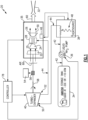
- FIG. 1 schematically illustrates one example disclosed alternate fueled turbine engine assembly 20.
- the engine assembly 20 uses a vaporized ammonia based fuel mixed with a core gas flow 66 in a combustor 28 to generate a high energy gas flow 30 that expands through a turbine section 26 to drive a compressor section 24 of a main turbine engine 35.
- the disclosed vaporized ammonia based fuel may include ammonia, decomposition products of ammonia and/or a mixture of ammonia and decomposition products.
- Ammonia does not contain carbon, but does have a fuel energy similar to alcohols such as methanol. Ammonia can also be transported and stored in liquid form at moderate pressure and temperature. For example, ammonia is a liquid at a pressure of about 8.5 atm and a temperature of 20°C. Alternatively, ammonia is a liquid at a pressure of 1 atm and a temperature of -33°C. These properties make ammonia attractive as alternate fuel that produces no carbon dioxide.
- the disclosed engine assembly 20 uses heat to transform ammonia fuel in a liquid state into a vaporized ammonia based fuel.
- the vaporized ammonia based fuel 44 is expanded through a turbo-expander 40 to create shaft work and then delivered to the combustor 28 to generate additional power and shaft work utilized to generate a thrust producing flow 60 by the main engine 35.
- the vaporized ammonia based fuel 44 is generated from a liquid ammonia fuel 42 stored in a fuel storage tank 34.
- the fuel storage tank 34 stores ammonia fuel 42 in a liquid state at a pressure and temperature that maintains the ammonia fuel 42 in a liquid state.
- the specific pressure and temperature required to maintain the ammonia fuel 42 in the liquid state may vary in different embodiments.
- the ammonia fuel 42 is maintained in the liquid state by storing at a temperature below about -33 °C and at a pressure at or below approximately 1 atm.
- the ammonia fuel 42 is maintained in the fuel storage tank at a pressure of about 8.5 atm at a temperature of 20 °C.
- the ammonia fuel is maintained in a liquid form at a pressure of about 1 atm and a temperature of about -33 °C. It should be appreciated that the specific temperature and pressure of ammonia may vary depending on application specific conditions.
- Ammonia fuel 42 in a liquid state is pressurized to a first pressure by a liquid pump 36.
- the liquid pump 36 raises the pressure to a point where the ammonia fuel 42 is of a pressure greater than is needed for communication into the combustor 28.
- the pressurized liquid ammonia fuel 42 is then heated within a thermal transfer assembly 38.
- Thermal energy is drawn from various heat sources including heat producing engine systems as is schematically shown at 46. Heat producing systems can include electric systems, combustion systems, turbine systems, lubrication systems and air cooling systems.
- the work required to pressurize ammonia fuel 42 in a liquid state to a high pressure is relatively small compared to the work created by turbo-expanding the heated, gaseous ammonia (or its decomposition products) in the turbo-expander 40.
- the heat used to raise the temperature of the ammonia fuel produces additional work that can be captured to reduce the load on the main engine 35 that in turn enables more work or thrust to be produced from a given quantity of fuel.
- heat producing systems onboard an aircraft may also be utilized to supply heat required to vaporize the ammonia fuel 42.
- Ammonia fuel exhausted from the thermal transfer assembly 38 is in a gas state and is communicated to an inlet 50 of a turbo-expander 40 and exhausted through an outlet 52 to the combustor 28.
- the turbo-expander 40 drives a shaft 58 that is coupled though a mechanical coupling 56 to drive engine and/or aircraft systems as is schematically shown at 54.
- the engine and/or aircraft systems can include pumps, generators, gearboxes and any other systems that would normally be powered through a coupling to a main engine shaft.
- the turbo-expander 40 is further coupled to drive a low pressure compressor section 22 of the main turbine engine 35.
- the high pressure compressor section 24 is coupled by way of shaft 25 to a high pressure turbine section 26.
- the high pressure compressor section 24, combustor 28 and high pressure turbine 26 provide a gas generator that produces the high energy exhaust flow 30 utilized to produce thrust. Any load placed on the main engine 35 reduces the amount of thrust that can be produced.
- the turbo-expander 40 uses energy in the vaporized ammonia based fuel 44 to reduce the amount of fuel required to produce the exhaust flow, thereby improving engine efficiency.
- the thrust producing flow 60 can be directed through a nozzle 32 to generate thrust. Additionally, the exhaust gas flow 30 can be used to drive a turbine that in turn would drive a fan to produce a bypass flow that increases thrust.
- a controller 78 is provided to control operation of the pump 36 and the turbo-expander 40 to desired engine operating demands and conditions. It should be appreciated, that the main engine 35 is shown schematically and that other structures and engine configurations such as 2-spool, 3-spool and geared turbofan engines would benefit from this disclosure and are within the contemplation and scope of this disclosure. Moreover, a land based turbine engine would also benefit from application of the features of this disclosure.
- the example engine assembly 62 includes the turbo-expander 40 that produces additional shaft work from the expansion of products from the cracking or decomposition of an ammonia based fuel 72.
- the engine assembly 62 includes a main engine 65 and a thermal transfer system 64 that utilizes heat from the high energy exhaust gas flow 30 generated in the combustor 28 to thermally decompose the ammonia fuel 42.
- the thermal transfer system 64 includes heat exchangers 74 in thermal communication with the exhaust gas flow 30 generated by the combustor 28.
- the higher heat energy generated aft of the combustor 28 elevates the temperature of the liquid ammonia fuel 42 and helps to decompose the ammonia into hydrogen and nitrogen according to the chemical equation:
- the cracked fuel has increased fuel chemical energy and can therefore provide increased engine work output or thrust output without increased fuel flow and thereby improves engine fuel efficiency.
- the cracking process is endothermic and therefore additional heat absorption capacity becomes available at a given fuel temperature, thereby enabling greater heat absorption before the fuel temperature approaches the temperature of the heat source.
- the cracking process changes the chemical composition of the ammonia fuel and thereby also changes its vapor-liquid equilibrium properties which provide greater turbo-expansion of the cracked gas.
- the saturation temperature where vapor begins to condense to liquid, is much lower for H 2 and N 2 than it is for NH 3 .
- the conversion of some or all of the NH 3 to H 2 and N 2 allows a larger temperature drop and more work extraction across the turbo-expander 40 without crossing the vapor-liquid equilibrium line than would be possible with pure NH 3 as the working fluid in the turbo-expander.
- This property can be advantageously used when cracking is included in the process by pumping the liquid fuel to a higher pressure before it is heated and cracked, thereby enabling a greater pressure and temperature drop during turbo-expansion. Cracking at least some of the ammonia fuel to form hydrogen further improves the flammability of the fuel, thus facilitating both ignition and stabilization of combustion in the main engine 65.
- the example main engine 65 includes a free power turbine 68 that drives an output shaft 70.
- the free power turbine 68 is driven by expansion of the exhaust gas flow 30 aft of the high pressure turbine 24.
- the free power turbine 68 is not coupled to drive other structures of the main engine 65 and therefore may more efficiently drive accessory components or a propulsive fan 76, at their desired speeds, as is schematically shown.
- some portion of shaft power from a turbine is typically required to drive accessory components and/or other compressor sections such as the low pressure compressor 22.
- the turbo-expander 40 uses energy from the cracked ammonia based fuel 72 to drive an accessory component 54 and/or the low pressure compressor 22. Accordingly, power generated by the power turbine 68 to drive the shaft 70 is increased and the overall engine efficiency is improved.
- the engine assembly 80 includes a fuel cell system 82 that is supplied with vaporized ammonia based fuel 44 to generate electric power schematically shown at 84.
- the fuel cell system 82 may be a direct-ammonia fuel cell, or a system that includes conversion of ammonia to hydrogen for use in a hydrogen fuel cell.
- the electric power 84 in this example is utilized to drive an electric motor 86.
- the electric motor 86 includes an output shaft 92 that drives an engine and/or aircraft system schematically indicated at 88. Vaporized ammonia based fuel 44 expands through the turbo-expander 40 to power the shaft 58.
- the shaft 58 can be coupled to drive various needed aircraft and/or engine accessories as is schematically shown at 90.
- the aircraft/engine accessory 90 may be a pump, a generator and/or any other structure utilizing rotary shaft power.
- the heat 48 for vaporizing the ammonia fuel 42 may be provided by any heat producing structure or device associated with an engine, fuel cell system, and/or aircraft.
- the disclosed engine assembly 80 may be utilized as a standalone engine or as an accessory unit in concert with a turbine engine to increase overall engine efficiency.
- the disclosed assemblies provide for the advantageous use of ammonia fuel to improve engine efficiency and reduce carbon emission.
- the disclosed systems use advantageous properties of ammonia to convert ammonia fuel into useful work prior to combustion that enables improved engine efficiencies.
Landscapes
- Engineering & Computer Science (AREA)
- Chemical & Material Sciences (AREA)
- Combustion & Propulsion (AREA)
- Mechanical Engineering (AREA)
- General Engineering & Computer Science (AREA)
- Engine Equipment That Uses Special Cycles (AREA)
Claims (12)
- Energiegewinnungssystem, umfassend:eine Ammoniakkraftstofflagertankbaugruppe (34), die dazu konfiguriert ist, einen flüssigen Ammoniakkraftstoff zu lagern;eine Wärmeübertragungsbaugruppe (38; 64), die dazu konfiguriert ist, den flüssigen Ammoniakkraftstoff in einen verdampften ammoniakbasierten Kraftstoff umzuwandeln;einen Turboexpander (40), der dazu konfiguriert ist, den verdampften ammoniakbasierten Kraftstoff zu expandieren, um Arbeit zu gewinnen;einen Niederdruckverdichter (22), wobei der Turboexpander (40) dazu gekoppelt ist, den Niederdruckverdichter (22) anzutreiben; undeine Energieumwandlungsvorrichtung, die eine Brennkammer (28) beinhaltet, wobei die Energieumwandlungsvorrichtung dazu konfiguriert ist, den verdampften ammoniakbasierten Kraftstoff aus dem Turboexpander (40) zu verwenden, um eine Arbeitsleistung zu erzeugen, wobei der Niederdruckverdichter (22) in Strömungsverbindung mit der Brennkammer (28) steht, der Niederdruckverdichter (22) Luft unter Druck setzt, die mit dem verdampften ammoniakbasierten Kraftstoff in der Brennkammer (28) zu vermischen ist, und der verdampfte ammoniakbasierte Kraftstoff mit Luft vermischt und in der Brennkammer (28) gezündet wird, um einen energiereichen Abgasstrom zu erzeugen, der durch eine Turbine (26) expandiert wird.
- Energiegewinnungssystem nach Anspruch 1, ferner umfassend eine Flüssigkeitspumpe (36), die dazu konfiguriert ist, einen Druck des flüssigen Ammoniakkraftstoffs auf einen Druck zu erhöhen, der höher ist als ein Druck des flüssigen Ammoniakkraftstoffs in dem Ammoniakkraftstofflagertank (34).
- Energiegewinnungssystem nach Anspruch 1 oder 2, wobei die Ammoniakkraftstofflagertankbaugruppe (34) dazu konfiguriert ist, den flüssigen Ammoniakkraftstoff bei einer Temperatur und einem Druck zu lagern, die sich von einer Umgebungstemperatur und einem Umgebungsdruck unterscheiden.
- Energiegewinnungssystem nach einem der vorhergehenden Ansprüche, ferner umfassend eine Flüssigkeitspumpe (36), die dazu konfiguriert ist, einen Druck des flüssigen Ammoniakkraftstoffs auf einen ersten Druck zu erhöhen, der höher ist als ein Druck des flüssigen Ammoniakkraftstoffs in dem Ammoniakkraftstofflagertank (34), wobei der erste Druck höher ist als ein Druck des verdampften ammoniakbasierten Kraftstoffs, der in die Brennkammer (28) geleitet wird.
- Energiegewinnungssystem nach Anspruch 3 oder 4, wobei die Wärmeübertragungsbaugruppe (38; 64) mit einem Kernstrom an die Turbine (26) in Verbindung steht.
- Energiegewinnungssystem nach einem der vorhergehenden Ansprüche, wobei die Wärmeübertragungsbaugruppe (38; 64) dazu konfiguriert ist, den Ammoniakkraftstoff zu erwärmen, um mindestens einen Teil des Ammoniakkraftstoffs in Wasserstoff und Stickstoff zu zerlegen.
- Energiegewinnungssystem nach einem der vorhergehenden Ansprüche, wobei die Wärmeübertragungsbaugruppe (38; 64) vor dem Turboexpander (40) angeordnet ist.
- Energiegewinnungssystem nach einem der vorhergehenden Ansprüche, wobei die Energieumwandlungsvorrichtung eine Brennstoffzelle (82) beinhaltet, die dazu konfiguriert ist, elektrische Leistung zum Antreiben eines Elektromotors (86) zu erzeugen.
- Verfahren zum Betreiben eines Energiegewinnungssystems, umfassend:Umwandeln eines Ammoniakkraftstoffs in einer flüssigen Form in einen verdampften ammoniakbasierten Kraftstoff;Expandieren des verdampften ammoniakbasierten Kraftstoffs durch einen Turboexpander (40);Leiten des verdampften ammoniakbasierten Kraftstoffs aus dem Turboexpander (40) in eine Energieumwandlungsvorrichtung, wobei die Energieumwandlungsvorrichtung eine Brennkammer (28) umfasst, in der der verdampfte ammoniakbasierte Kraftstoff mit Luft vermischt und gezündet wird, um einen energiereichen Abgasstrom zu erzeugen, wobei der Turboexpander (40) mit einem Verdichter (22) gekoppelt ist, der dazu konfiguriert ist, Luft unter Druck zu setzen und die unter Druck stehende Luft in die Brennkammer (28) zu leiten; undwobei der energiereiche Abgasstrom durch eine Turbine (26) expandiert wird.
- Verfahren nach Anspruch 9, beinhaltend Unterdrucksetzen des Ammoniakkraftstoffs in der flüssigen Form auf einen ersten Druck, der höher ist als der Druck des in einem Kraftstofflagertank (34) gelagerten Ammoniakkraftstoffs.
- Verfahren nach Anspruch 9 oder 10, beinhaltend Umwandeln des Ammoniakkraftstoffs innerhalb einer Wärmeübertragungsbaugruppe (38; 64), die in thermischer Verbindung mit einer Wärmequelle steht, optional beinhaltend Zerlegen von mindestens einem Teil des Ammoniakkraftstoffs in Wasserstoff und Stickstoff unter Einwirkung von Wärme in der Wärmeübertragungsbaugruppe (38; 64).
- Verfahren nach einem der Ansprüche 9 bis 11, beinhaltend Umwandeln des Ammoniakkraftstoffs in flüssige Form innerhalb einer Wärmeübertragungsbaugruppe (38, 64), die in thermischer Verbindung mit einem Kernstrom steht.
Applications Claiming Priority (1)
| Application Number | Priority Date | Filing Date | Title |
|---|---|---|---|
| US16/858,858 US20210332759A1 (en) | 2020-04-27 | 2020-04-27 | Engine using heated and turbo-expanded ammonia fuel |
Publications (2)
| Publication Number | Publication Date |
|---|---|
| EP3943732A1 EP3943732A1 (de) | 2022-01-26 |
| EP3943732B1 true EP3943732B1 (de) | 2025-02-12 |
Family
ID=75728620
Family Applications (1)
| Application Number | Title | Priority Date | Filing Date |
|---|---|---|---|
| EP21170781.5A Active EP3943732B1 (de) | 2020-04-27 | 2021-04-27 | Motor mit einem erwärmten und turboexpandierten ammoniakkraftstoff |
Country Status (2)
| Country | Link |
|---|---|
| US (2) | US20210332759A1 (de) |
| EP (1) | EP3943732B1 (de) |
Families Citing this family (29)
| Publication number | Priority date | Publication date | Assignee | Title |
|---|---|---|---|---|
| GB2608643B (en) * | 2021-07-09 | 2025-01-08 | Reaction Engines Ltd | Thermally integrated ammonia fuelled engine |
| US12044176B2 (en) | 2021-07-09 | 2024-07-23 | Rtx Corporation | Turbine engines having hydrogen fuel systems |
| KR102536353B1 (ko) * | 2021-10-27 | 2023-05-26 | 두산에너빌리티 주식회사 | 복합 발전 시스템 및 복합 발전 시스템의 운영 방법 |
| GB2614756B (en) * | 2022-01-18 | 2025-04-09 | Equinor Energy As | Energy harvesting in subsea shuttle |
| KR102583688B1 (ko) * | 2022-02-14 | 2023-09-26 | 두산에너빌리티 주식회사 | 복합 발전 시스템 및 복합 발전 시스템의 구동 방법 |
| US11802508B2 (en) * | 2022-03-30 | 2023-10-31 | Rtx Corporation | Efficient turbine engine using integrated ammonia fuel processing |
| FR3134429B1 (fr) * | 2022-04-12 | 2025-04-11 | Safran | Système et procédé d’alimentation en carburant pour turbomachine d’aéronef |
| CN114718730B (zh) * | 2022-04-19 | 2023-06-30 | 西安交通大学 | 一种氨转化为氢的燃氢燃气轮机系统及控制方法 |
| GB202207929D0 (en) | 2022-05-30 | 2022-07-13 | Rolls Royce Plc | Hydrogen-fuelled gas turbine engine with fuel-to-air turbocharger |
| CN115030816B (zh) * | 2022-06-16 | 2025-04-18 | 哈尔滨工业大学 | 一种间冷换热式零碳排放燃气轮机循环系统及循环方法 |
| CN115217565A (zh) * | 2022-07-07 | 2022-10-21 | 上海发电设备成套设计研究院有限责任公司 | 一种采用氨燃料的联合发电装置系统及方法 |
| US12103699B2 (en) | 2022-07-08 | 2024-10-01 | Rtx Corporation | Hybrid electric power for turbine engines having hydrogen fuel systems |
| US11987377B2 (en) * | 2022-07-08 | 2024-05-21 | Rtx Corporation | Turbo expanders for turbine engines having hydrogen fuel systems |
| US20240018908A1 (en) * | 2022-07-14 | 2024-01-18 | Pratt & Whitney Canada Corp. | Aircraft power plant with hydrogen turbo-expander |
| CN115320862B (zh) * | 2022-08-22 | 2024-08-20 | 哈尔滨工业大学 | 一种氨燃料电池无人机动力系统及其工作方法 |
| CN115347216B (zh) * | 2022-09-08 | 2025-09-09 | 中国科学院大连化学物理研究所 | 紧凑型低温直接氨燃料电池系统 |
| CN115411303B (zh) * | 2022-09-08 | 2025-09-05 | 中国科学院大连化学物理研究所 | 低温直接氨燃料电池系统 |
| WO2025106056A2 (en) * | 2022-09-23 | 2025-05-22 | University Of Central Florida Research Foundation, Inc. | System and method for using ammonia as a fuel source for engines |
| KR102897162B1 (ko) * | 2023-05-30 | 2025-12-09 | 두산에너빌리티 주식회사 | 암모니아 분해 시스템을 포함하는 가스터빈 플랜트 |
| KR102921605B1 (ko) | 2023-05-30 | 2026-02-02 | 두산에너빌리티 주식회사 | 암모니아 분해 시스템을 포함하는 가스터빈 플랜트 |
| KR20240171446A (ko) | 2023-05-30 | 2024-12-09 | 두산에너빌리티 주식회사 | 암모니아 분해 시스템을 포함하는 가스터빈 플랜트 |
| US12385433B2 (en) | 2023-05-30 | 2025-08-12 | Doosan Enerbility Co., Ltd. | Gas turbine plant with ammonia decomposition system |
| KR102897161B1 (ko) * | 2023-05-30 | 2025-12-09 | 두산에너빌리티 주식회사 | 암모니아 분해 시스템을 포함하는 가스터빈 플랜트 |
| US12264621B2 (en) * | 2023-05-30 | 2025-04-01 | Doosan Enerbility Co., Ltd. | Gas turbine plant with ammonia decomposition system |
| US12486803B2 (en) | 2023-06-16 | 2025-12-02 | Pratt & Whitney Canada Corp. | Gas turbine engine system with fuel driven turbine |
| EP4732359A2 (de) | 2023-06-26 | 2026-04-29 | Tennessee Technological University | Integrierte festoxidbrennstoffzellenbrennkammeranordnung, system und verfahren dafür |
| WO2025183725A2 (en) | 2023-08-08 | 2025-09-04 | Tennessee Technological University | Fuel cell turboelectric fan for an aircraft |
| IT202300017655A1 (it) * | 2023-08-28 | 2025-02-28 | Nuovo Pignone Tecnologie Srl | Sistema ausiliario di turbina a gas per il condizionamento dell'nh3 |
| US12467403B1 (en) | 2024-06-28 | 2025-11-11 | Pratt & Whitney Canada Corp. | Powerplant fuel system utilizing ammonia |
Family Cites Families (7)
| Publication number | Priority date | Publication date | Assignee | Title |
|---|---|---|---|---|
| US4599862A (en) * | 1985-02-05 | 1986-07-15 | Bergeron Robert M | Turbocharger for two-cycle engines and method of operation thereof |
| US4999993A (en) * | 1987-11-25 | 1991-03-19 | Fluor Corporation | Reactor expander topping cycle |
| DE102010006153A1 (de) * | 2010-01-29 | 2011-08-04 | Siemens Aktiengesellschaft, 80333 | Elektrisch angetriebenes Luftfahrzeug |
| WO2012058277A1 (en) * | 2010-10-26 | 2012-05-03 | Icr Tubine Engine Corporation | Utilizing heat discarded from a gas turbine engine |
| FR3042009B1 (fr) * | 2015-10-05 | 2018-07-13 | Safran Aircraft Engines | Turbo moteur a soufflantes deportees avec un systeme differentiel |
| ES2963067T3 (es) * | 2016-03-14 | 2024-03-25 | Equinor Energy As | Craqueo de amoníaco |
| US11047307B2 (en) * | 2018-09-14 | 2021-06-29 | Raytheon Technologies Corporation | Hybrid expander cycle with intercooling and turbo-generator |
-
2020
- 2020-04-27 US US16/858,858 patent/US20210332759A1/en not_active Abandoned
-
2021
- 2021-04-27 EP EP21170781.5A patent/EP3943732B1/de active Active
-
2022
- 2022-08-26 US US17/896,431 patent/US20220412263A1/en not_active Abandoned
Also Published As
| Publication number | Publication date |
|---|---|
| US20210332759A1 (en) | 2021-10-28 |
| EP3943732A1 (de) | 2022-01-26 |
| US20220412263A1 (en) | 2022-12-29 |
Similar Documents
| Publication | Publication Date | Title |
|---|---|---|
| EP3943732B1 (de) | Motor mit einem erwärmten und turboexpandierten ammoniakkraftstoff | |
| EP4001617B1 (de) | Motor mit gecracktem ammoniakkraftstoff | |
| US12473856B2 (en) | Cracking and separation of ammonia fuel | |
| US11448133B2 (en) | Moderate pressure liquid hydrogen storage for hybrid-electric propulsion system | |
| US11629858B2 (en) | Turboexpander inter-stage heating and NH3 cracking | |
| EP4253739A1 (de) | Effizientes turbinentriebwerk mit integrierter ammoniak-brennstoffverarbeitung | |
| US7827794B1 (en) | Ultra low emissions fast starting power plant | |
| US20240052792A1 (en) | Inter-cooled preheat of steam injected turbine engine | |
| US20110126549A1 (en) | Ultra low emissions fast starting power plant | |
| US12270341B2 (en) | Gas turbine engine fuel system | |
| JP2016508912A (ja) | Lngボイルオフを管理する方法及びlngボイルオフの管理組立体 | |
| US12180893B2 (en) | Hydrogen steam injected turbine engine with turboexpander heat recovery | |
| US20240141831A1 (en) | Hydrogen steam injected turbine engine with cooled cooling air | |
| US12473858B2 (en) | Partial exhaust bottoming cycle | |
| US20240360791A1 (en) | Cryo-assisted bottoming cycle heat source sequencing | |
| RU135000U1 (ru) | Углеродно-водородный прямоточный двигатель | |
| US20260015969A1 (en) | Fuel cell exhaust condensation with turbomachinery water augmentation using cryogenic bottoming cycle | |
| EP4678893A1 (de) | Kryounterstützte bottoming-zyklus-wärmequellensequenzierung | |
| CN118934131A (zh) | 一种燃烧碳氢燃料的半闭式超临界二氧化碳布雷顿循环零碳排放混合动力系统 |
Legal Events
| Date | Code | Title | Description |
|---|---|---|---|
| PUAI | Public reference made under article 153(3) epc to a published international application that has entered the european phase |
Free format text: ORIGINAL CODE: 0009012 |
|
| STAA | Information on the status of an ep patent application or granted ep patent |
Free format text: STATUS: THE APPLICATION HAS BEEN PUBLISHED |
|
| AK | Designated contracting states |
Kind code of ref document: A1 Designated state(s): AL AT BE BG CH CY CZ DE DK EE ES FI FR GB GR HR HU IE IS IT LI LT LU LV MC MK MT NL NO PL PT RO RS SE SI SK SM TR |
|
| STAA | Information on the status of an ep patent application or granted ep patent |
Free format text: STATUS: REQUEST FOR EXAMINATION WAS MADE |
|
| 17P | Request for examination filed |
Effective date: 20220726 |
|
| RBV | Designated contracting states (corrected) |
Designated state(s): AL AT BE BG CH CY CZ DE DK EE ES FI FR GB GR HR HU IE IS IT LI LT LU LV MC MK MT NL NO PL PT RO RS SE SI SK SM TR |
|
| RAP3 | Party data changed (applicant data changed or rights of an application transferred) |
Owner name: RTX CORPORATION |
|
| GRAP | Despatch of communication of intention to grant a patent |
Free format text: ORIGINAL CODE: EPIDOSNIGR1 |
|
| STAA | Information on the status of an ep patent application or granted ep patent |
Free format text: STATUS: GRANT OF PATENT IS INTENDED |
|
| INTG | Intention to grant announced |
Effective date: 20240906 |
|
| GRAS | Grant fee paid |
Free format text: ORIGINAL CODE: EPIDOSNIGR3 |
|
| GRAA | (expected) grant |
Free format text: ORIGINAL CODE: 0009210 |
|
| STAA | Information on the status of an ep patent application or granted ep patent |
Free format text: STATUS: THE PATENT HAS BEEN GRANTED |
|
| AK | Designated contracting states |
Kind code of ref document: B1 Designated state(s): AL AT BE BG CH CY CZ DE DK EE ES FI FR GB GR HR HU IE IS IT LI LT LU LV MC MK MT NL NO PL PT RO RS SE SI SK SM TR |
|
| REG | Reference to a national code |
Ref country code: GB Ref legal event code: FG4D |
|
| REG | Reference to a national code |
Ref country code: CH Ref legal event code: EP |
|
| REG | Reference to a national code |
Ref country code: DE Ref legal event code: R096 Ref document number: 602021025860 Country of ref document: DE |
|
| REG | Reference to a national code |
Ref country code: IE Ref legal event code: FG4D |
|
| REG | Reference to a national code |
Ref country code: NL Ref legal event code: MP Effective date: 20250212 |
|
| PG25 | Lapsed in a contracting state [announced via postgrant information from national office to epo] |
Ref country code: RS Free format text: LAPSE BECAUSE OF FAILURE TO SUBMIT A TRANSLATION OF THE DESCRIPTION OR TO PAY THE FEE WITHIN THE PRESCRIBED TIME-LIMIT Effective date: 20250512 |
|
| PG25 | Lapsed in a contracting state [announced via postgrant information from national office to epo] |
Ref country code: FI Free format text: LAPSE BECAUSE OF FAILURE TO SUBMIT A TRANSLATION OF THE DESCRIPTION OR TO PAY THE FEE WITHIN THE PRESCRIBED TIME-LIMIT Effective date: 20250212 |
|
| PG25 | Lapsed in a contracting state [announced via postgrant information from national office to epo] |
Ref country code: PL Free format text: LAPSE BECAUSE OF FAILURE TO SUBMIT A TRANSLATION OF THE DESCRIPTION OR TO PAY THE FEE WITHIN THE PRESCRIBED TIME-LIMIT Effective date: 20250212 |
|
| PGFP | Annual fee paid to national office [announced via postgrant information from national office to epo] |
Ref country code: DE Payment date: 20250319 Year of fee payment: 5 |
|
| PG25 | Lapsed in a contracting state [announced via postgrant information from national office to epo] |
Ref country code: ES Free format text: LAPSE BECAUSE OF FAILURE TO SUBMIT A TRANSLATION OF THE DESCRIPTION OR TO PAY THE FEE WITHIN THE PRESCRIBED TIME-LIMIT Effective date: 20250212 |
|
| REG | Reference to a national code |
Ref country code: LT Ref legal event code: MG9D |
|
| PG25 | Lapsed in a contracting state [announced via postgrant information from national office to epo] |
Ref country code: IS Free format text: LAPSE BECAUSE OF FAILURE TO SUBMIT A TRANSLATION OF THE DESCRIPTION OR TO PAY THE FEE WITHIN THE PRESCRIBED TIME-LIMIT Effective date: 20250612 Ref country code: NO Free format text: LAPSE BECAUSE OF FAILURE TO SUBMIT A TRANSLATION OF THE DESCRIPTION OR TO PAY THE FEE WITHIN THE PRESCRIBED TIME-LIMIT Effective date: 20250512 |
|
| PG25 | Lapsed in a contracting state [announced via postgrant information from national office to epo] |
Ref country code: NL Free format text: LAPSE BECAUSE OF FAILURE TO SUBMIT A TRANSLATION OF THE DESCRIPTION OR TO PAY THE FEE WITHIN THE PRESCRIBED TIME-LIMIT Effective date: 20250212 |
|
| PG25 | Lapsed in a contracting state [announced via postgrant information from national office to epo] |
Ref country code: HR Free format text: LAPSE BECAUSE OF FAILURE TO SUBMIT A TRANSLATION OF THE DESCRIPTION OR TO PAY THE FEE WITHIN THE PRESCRIBED TIME-LIMIT Effective date: 20250212 |
|
| PG25 | Lapsed in a contracting state [announced via postgrant information from national office to epo] |
Ref country code: PT Free format text: LAPSE BECAUSE OF FAILURE TO SUBMIT A TRANSLATION OF THE DESCRIPTION OR TO PAY THE FEE WITHIN THE PRESCRIBED TIME-LIMIT Effective date: 20250612 Ref country code: LV Free format text: LAPSE BECAUSE OF FAILURE TO SUBMIT A TRANSLATION OF THE DESCRIPTION OR TO PAY THE FEE WITHIN THE PRESCRIBED TIME-LIMIT Effective date: 20250212 |
|
| PG25 | Lapsed in a contracting state [announced via postgrant information from national office to epo] |
Ref country code: BG Free format text: LAPSE BECAUSE OF FAILURE TO SUBMIT A TRANSLATION OF THE DESCRIPTION OR TO PAY THE FEE WITHIN THE PRESCRIBED TIME-LIMIT Effective date: 20250212 Ref country code: GR Free format text: LAPSE BECAUSE OF FAILURE TO SUBMIT A TRANSLATION OF THE DESCRIPTION OR TO PAY THE FEE WITHIN THE PRESCRIBED TIME-LIMIT Effective date: 20250513 |
|
| REG | Reference to a national code |
Ref country code: AT Ref legal event code: MK05 Ref document number: 1766225 Country of ref document: AT Kind code of ref document: T Effective date: 20250212 |
|
| PG25 | Lapsed in a contracting state [announced via postgrant information from national office to epo] |
Ref country code: SE Free format text: LAPSE BECAUSE OF FAILURE TO SUBMIT A TRANSLATION OF THE DESCRIPTION OR TO PAY THE FEE WITHIN THE PRESCRIBED TIME-LIMIT Effective date: 20250212 |
|
| PG25 | Lapsed in a contracting state [announced via postgrant information from national office to epo] |
Ref country code: SM Free format text: LAPSE BECAUSE OF FAILURE TO SUBMIT A TRANSLATION OF THE DESCRIPTION OR TO PAY THE FEE WITHIN THE PRESCRIBED TIME-LIMIT Effective date: 20250212 |
|
| PG25 | Lapsed in a contracting state [announced via postgrant information from national office to epo] |
Ref country code: DK Free format text: LAPSE BECAUSE OF FAILURE TO SUBMIT A TRANSLATION OF THE DESCRIPTION OR TO PAY THE FEE WITHIN THE PRESCRIBED TIME-LIMIT Effective date: 20250212 |
|
| PG25 | Lapsed in a contracting state [announced via postgrant information from national office to epo] |
Ref country code: IT Free format text: LAPSE BECAUSE OF FAILURE TO SUBMIT A TRANSLATION OF THE DESCRIPTION OR TO PAY THE FEE WITHIN THE PRESCRIBED TIME-LIMIT Effective date: 20250212 |
|
| PG25 | Lapsed in a contracting state [announced via postgrant information from national office to epo] |
Ref country code: AT Free format text: LAPSE BECAUSE OF FAILURE TO SUBMIT A TRANSLATION OF THE DESCRIPTION OR TO PAY THE FEE WITHIN THE PRESCRIBED TIME-LIMIT Effective date: 20250212 |
|
| PG25 | Lapsed in a contracting state [announced via postgrant information from national office to epo] |
Ref country code: CZ Free format text: LAPSE BECAUSE OF FAILURE TO SUBMIT A TRANSLATION OF THE DESCRIPTION OR TO PAY THE FEE WITHIN THE PRESCRIBED TIME-LIMIT Effective date: 20250212 Ref country code: EE Free format text: LAPSE BECAUSE OF FAILURE TO SUBMIT A TRANSLATION OF THE DESCRIPTION OR TO PAY THE FEE WITHIN THE PRESCRIBED TIME-LIMIT Effective date: 20250212 |
|
| PG25 | Lapsed in a contracting state [announced via postgrant information from national office to epo] |
Ref country code: RO Free format text: LAPSE BECAUSE OF FAILURE TO SUBMIT A TRANSLATION OF THE DESCRIPTION OR TO PAY THE FEE WITHIN THE PRESCRIBED TIME-LIMIT Effective date: 20250212 |
|
| PG25 | Lapsed in a contracting state [announced via postgrant information from national office to epo] |
Ref country code: SK Free format text: LAPSE BECAUSE OF FAILURE TO SUBMIT A TRANSLATION OF THE DESCRIPTION OR TO PAY THE FEE WITHIN THE PRESCRIBED TIME-LIMIT Effective date: 20250212 |
|
| REG | Reference to a national code |
Ref country code: DE Ref legal event code: R097 Ref document number: 602021025860 Country of ref document: DE |
|
| REG | Reference to a national code |
Ref country code: CH Ref legal event code: H13 Free format text: ST27 STATUS EVENT CODE: U-0-0-H10-H13 (AS PROVIDED BY THE NATIONAL OFFICE) Effective date: 20251125 |
|
| PG25 | Lapsed in a contracting state [announced via postgrant information from national office to epo] |
Ref country code: LU Free format text: LAPSE BECAUSE OF NON-PAYMENT OF DUE FEES Effective date: 20250427 |
|
| PLBE | No opposition filed within time limit |
Free format text: ORIGINAL CODE: 0009261 |
|
| STAA | Information on the status of an ep patent application or granted ep patent |
Free format text: STATUS: NO OPPOSITION FILED WITHIN TIME LIMIT |
|
| PG25 | Lapsed in a contracting state [announced via postgrant information from national office to epo] |
Ref country code: MC Free format text: LAPSE BECAUSE OF FAILURE TO SUBMIT A TRANSLATION OF THE DESCRIPTION OR TO PAY THE FEE WITHIN THE PRESCRIBED TIME-LIMIT Effective date: 20250212 |
|
| REG | Reference to a national code |
Ref country code: BE Ref legal event code: MM Effective date: 20250430 |
|
| PG25 | Lapsed in a contracting state [announced via postgrant information from national office to epo] |
Ref country code: BE Free format text: LAPSE BECAUSE OF NON-PAYMENT OF DUE FEES Effective date: 20250430 |
|
| PG25 | Lapsed in a contracting state [announced via postgrant information from national office to epo] |
Ref country code: CH Free format text: LAPSE BECAUSE OF NON-PAYMENT OF DUE FEES Effective date: 20250430 |
|
| 26N | No opposition filed |
Effective date: 20251113 |
|
| PGFP | Annual fee paid to national office [announced via postgrant information from national office to epo] |
Ref country code: GB Payment date: 20260319 Year of fee payment: 6 |
|
| PG25 | Lapsed in a contracting state [announced via postgrant information from national office to epo] |
Ref country code: IE Free format text: LAPSE BECAUSE OF NON-PAYMENT OF DUE FEES Effective date: 20250427 |
|
| PGFP | Annual fee paid to national office [announced via postgrant information from national office to epo] |
Ref country code: FR Payment date: 20260320 Year of fee payment: 6 |