EP3943809B1 - Phares de véhicule automobile pourvus de modules de projection - Google Patents
Phares de véhicule automobile pourvus de modules de projection Download PDFInfo
- Publication number
- EP3943809B1 EP3943809B1 EP21186577.9A EP21186577A EP3943809B1 EP 3943809 B1 EP3943809 B1 EP 3943809B1 EP 21186577 A EP21186577 A EP 21186577A EP 3943809 B1 EP3943809 B1 EP 3943809B1
- Authority
- EP
- European Patent Office
- Prior art keywords
- light
- guide plate
- light guide
- motor vehicle
- additional
- Prior art date
- Legal status (The legal status is an assumption and is not a legal conclusion. Google has not performed a legal analysis and makes no representation as to the accuracy of the status listed.)
- Active
Links
Images


Classifications
-
- F—MECHANICAL ENGINEERING; LIGHTING; HEATING; WEAPONS; BLASTING
- F21—LIGHTING
- F21S—NON-PORTABLE LIGHTING DEVICES; SYSTEMS THEREOF; VEHICLE LIGHTING DEVICES SPECIALLY ADAPTED FOR VEHICLE EXTERIORS
- F21S41/00—Illuminating devices specially adapted for vehicle exteriors, e.g. headlamps
- F21S41/20—Illuminating devices specially adapted for vehicle exteriors, e.g. headlamps characterised by refractors, transparent cover plates, light guides or filters
- F21S41/24—Light guides
-
- F—MECHANICAL ENGINEERING; LIGHTING; HEATING; WEAPONS; BLASTING
- F21—LIGHTING
- F21S—NON-PORTABLE LIGHTING DEVICES; SYSTEMS THEREOF; VEHICLE LIGHTING DEVICES SPECIALLY ADAPTED FOR VEHICLE EXTERIORS
- F21S41/00—Illuminating devices specially adapted for vehicle exteriors, e.g. headlamps
- F21S41/10—Illuminating devices specially adapted for vehicle exteriors, e.g. headlamps characterised by the light source
- F21S41/14—Illuminating devices specially adapted for vehicle exteriors, e.g. headlamps characterised by the light source characterised by the type of light source
- F21S41/141—Light emitting diodes [LED]
- F21S41/143—Light emitting diodes [LED] the main emission direction of the LED being parallel to the optical axis of the illuminating device
-
- F—MECHANICAL ENGINEERING; LIGHTING; HEATING; WEAPONS; BLASTING
- F21—LIGHTING
- F21S—NON-PORTABLE LIGHTING DEVICES; SYSTEMS THEREOF; VEHICLE LIGHTING DEVICES SPECIALLY ADAPTED FOR VEHICLE EXTERIORS
- F21S41/00—Illuminating devices specially adapted for vehicle exteriors, e.g. headlamps
- F21S41/10—Illuminating devices specially adapted for vehicle exteriors, e.g. headlamps characterised by the light source
- F21S41/14—Illuminating devices specially adapted for vehicle exteriors, e.g. headlamps characterised by the light source characterised by the type of light source
- F21S41/141—Light emitting diodes [LED]
- F21S41/147—Light emitting diodes [LED] the main emission direction of the LED being angled to the optical axis of the illuminating device
-
- F—MECHANICAL ENGINEERING; LIGHTING; HEATING; WEAPONS; BLASTING
- F21—LIGHTING
- F21S—NON-PORTABLE LIGHTING DEVICES; SYSTEMS THEREOF; VEHICLE LIGHTING DEVICES SPECIALLY ADAPTED FOR VEHICLE EXTERIORS
- F21S41/00—Illuminating devices specially adapted for vehicle exteriors, e.g. headlamps
- F21S41/20—Illuminating devices specially adapted for vehicle exteriors, e.g. headlamps characterised by refractors, transparent cover plates, light guides or filters
- F21S41/25—Projection lenses
- F21S41/255—Lenses with a front view of circular or truncated circular outline
Definitions
- the present invention relates to a motor vehicle headlight according to the preamble of claim 1.
- Such a motor vehicle headlight is from the FR 3 079 597 A1 already known.
- a projection light module comprises a first projection light module which comprises a first semiconductor light source, a first projection lens and a first additional light source as well as a first light guide plate.
- the first projection lens comprises a first optical axis and a first light entry surface that can be illuminated with the first additional light source through the first light guide plate.
- the first additional light source is arranged on a narrow side of the first light guide plate such that light emanating from the first additional light source enters the first light guide plate transversely to the first optical axis.
- the first light guide plate has a front emission side facing the first projection lens and a rear deflection side opposite the front emission side, as well as a first part closer to the first optical axis and a second part further away from the optical axis.
- the first part and the second part are components of the first light guide plate.
- a matrix function is understood here to mean that the high beam distribution has a plurality of matrix elements in the form of segments of the light distribution that can be individually darkened in order to avoid dazzling other road users and at the same time to achieve good illumination of the road with bright segments.
- both projection lenses of the projection light modules appear luminous even when only the low beam is switched on in order to achieve a uniform appearance between the partial high beam and the low beam
- an additional LED was previously installed on the LED board of the matrix high beam module and its light was directed to the lens entrance side via two metallized reflectors.
- the arrangement of the reflectors was chosen so that the light path of the matrix function is not disturbed and the reflection surface of the second reflector is close to the image plane of the projection lens.
- the matrix elements of the high beam distribution are generated via collecting lenses assigned to the respective LEDs, i.e. with a refractive attachment lens, and their imaging via the downstream common projection lens, the additional light used to brighten the projection lens runs via two metallized reflectors.
- the optical system for lens illumination of the high beam module differs from that of the low beam module. This means that the light color of the additional light differs from that of the low beam.
- the inevitable inclined arrangement of the second reflector of the known additional light means that it is not possible to get close enough to the image plane of the projection lens. This leads to an inhomogeneous appearance of the luminous lens.
- a homogeneous luminance is generated at the height of the front optics of the matrix light module using a light guide plate.
- the light guide is fed with additional light from one LED on the side of the matrix light LED board.
- the light propagating within the light guide plate is directed towards the projection lens by prisms attached to the back of the plate. This results in homogeneous illumination of the light guide plate.
- This and the position of the light guide in the image plane of the projection lens mean that the viewer already has a homogeneous appearance of the projection lens that corresponds to the shape of the projection lens, even if the projection lens is not completely illuminated for its actual purpose of generating a spotlight light distribution.
- the tilted arrangement further improves the homogeneity of the illumination of the first projection lens with additional light.
- the object of the invention is to achieve an even more uniform appearance between the partial high beam and the dipped beam.
- a preferred embodiment is characterized in that the first projection light module is a high beam module.
- the matrix high beam has the property that the appearance of the lens changes depending on the position of the light and dark matrix elements. Therefore, the invention, which ensures a more uniform appearance, has a particularly advantageous effect here.
- the motor vehicle headlight comprises a second projection light module comprising a second semiconductor light source, a second projection lens and a second additional light source as well as a second Light guide plate
- the second projection lens has a second optical axis and a second light entry surface which can be illuminated with the second additional light source through the second light guide plate
- the second additional light source is arranged on a narrow side of the second light guide plate such that light emanating from the second additional light source enters the second light guide plate transversely to the second optical axis and the second light guide plate has a front emission side facing the second projection lens and a rear deflection side opposite the front emission side as well as a first part closer to the second optical axis and a second part further away from the second optical axis, and that the light guide plate is arranged in a tilted position in which the first part of the second light guide plate is further away from the second projection lens along the second optical axis than the second part of the second light guide plate.
- the second projection light module has a mirror cover running from the back to the front in the motor vehicle headlight and that the light guide plate is arranged below the mirror cover.
- This design creates a low beam module with improved illumination of the projection lens.
- This design also surprisingly shows that the tilted arrangement further improves the homogeneity of the illumination of the second projection lens with additional light.
- a further preferred embodiment is characterized in that the light color of the additional light source is unchangeable and differs from the light color of the high beam and/or the low beam.
- This embodiment results in a fixed illumination of the remaining colorless light guide that is deliberately different in color from the light color of the high beam and/or the low beam and thus a correspondingly multi-colored illumination of the projection lens.
- a further preferred embodiment is characterized in that the first light guide plate and/or the second light guide plate has at least one colored region.
- the colored area is a light entry area of the otherwise colorless transparent light guide plate.
- the colored region is a colored coated light entry region of the otherwise colorless light guide plate.
- this attachment optic would be two-colored, as a so-called 2-component (2K) part.
- 2K 2-component
- the interface of the two components together with the entrance surface can be optimized with regard to a uniform colored illumination of the rest of the light guide (2.2).
- Another variant instead of a two-color light guide plate consists in a coating of the entrance surface of the otherwise colorless light guide plate, the optical properties of which are designed in such a way that it is only transparent to light of a fixed color or wavelength and absorbs or reflects all light of other colors or wavelengths.
- the light colour of the first and/or second additional light source is controllably variable and may differ from the light colour of the high beam and/or the low beam.
- first and/or second additional light source has individually controllable, differently colored light-emitting diodes.
- a temporally changing color of the lens illumination in particular a color that is deliberately different from the main light functions of the low beam and the high beam, cannot be realized with the above-mentioned state of the art.
- This limitation of the possible appearances with which, for example, a colored welcome light can be created with the headlights is eliminated by this design.
- a further preferred embodiment is characterized in that the individually controllable, differently colored light-emitting diodes comprise a red light-emitting light-emitting diode, a green light-emitting light-emitting diode and a blue light-emitting light-emitting diode.
- An alternative to the use of the light guide plate according to the invention could be to use an attachment optic that is common to both functions, i.e., for the function of generating a light distribution and the function of uniform illumination of the projection lenses.
- the Figure 1 a motor vehicle headlight 10 with a main beam direction 12 pointing forward v.
- the designation h indicates a rear position
- the designations r and 1 indicate a right side and a left side
- the designations o and u indicate an upper and a lower position.
- the motor vehicle headlight 10 has a first projection light module 14 and a second Projection light module 16.
- the location and position information front, rear, right, left, top and bottom each refer to an orientation of the motor vehicle headlight in space when used as intended in a motor vehicle.
- Figure 2 shows a vertical section running between front v and rear h through the motor vehicle headlight 10, which has a housing 18 whose light exit opening is covered by a transparent cover plate 20.
- the first projection light module 14 has a first semiconductor light source 22, a first projection lens 24 and a first additional light source 26 as well as a first light guide plate 28.
- the first projection lens 24 has a first optical axis 30 and a first light entry surface 32. The first light entry surface 32 can be illuminated with additional light 34 from the first additional light source 26 through the first light guide plate 28.
- the first additional light source 26 is arranged on a narrow side 36 of the first light guide plate 28 such that additional light 34 emanating from the first additional light source 26 enters the first light guide plate 28 transversely (namely laterally, in particular in the right-left direction) to the first optical axis 30 running in the front-back direction, and the first light guide plate 28 has a first front radiation side 38 facing the first projection lens 24 and a first rear deflection side 40 opposite the first front radiation side 38, as well as a closer to the first optical axis 30 and a second part 44 further away from the first optical axis 30.
- the first light guide plate 28 is arranged in a tilted position in which the first part 42 of the first light guide plate 28 is further away from the first projection lens 24 along the first optical axis 30 than the second part 44 of the first light guide plate 28.
- the light guide plate is not arranged at right angles to the first optical axis, particularly in the vertical section in which the first optical axis 30 also lies.
- Figure 3 shows the first projection light module 14 from the front.
- two additional light sources 26 are provided, one of which is arranged on a right narrow side 36.r and one on a left narrow side 36.1.
- the additional light 34 emanating from the additional light sources 26 enters the first light guide plate 28 from the side and is distributed evenly in the first light guide plate 28, also through internal total reflection.
- the additional light 34 is deflected so steeply to the first front emission side 38 of the first light guide plate 28 that it emerges there evenly distributed.
- the emitted additional light 34 is at least in the vertical Direction so that it evenly illuminates the first light entry surface 32 of the first projection lens 24.
- the Figures 2 and 3 The first projection light module 14 shown is a high beam module.
- the light emanating from the first semiconductor light source 22 is not shaded or redirected by a horizontal aperture.
- the first semiconductor light source 22 of the first projection light module 14 has n LEDs arranged next to one another, each of which illuminates exactly one first optical attachment section 56 of a first optical attachment 50 that is assigned to it alone.
- the number of first optical attachment sections 56 is also equal to n.
- the number n here is equal to 6, without n being limited to this value.
- the individual LEDs and the first additional light source 26 can be individually controlled with a control device 58 of the first projection light module 14.
- the Figure 3 visible light exit surfaces of the first optical attachment sections 56 are projected forwards by the first projection lens 24, with the images being arranged in the same way as the light exit surfaces of the first optical attachment sections 56. By darkening individual LEDs, sections of the high beam distribution can be darkened individually in order to avoid blinding other road users.
- the control unit 58 processes signals from a vehicle environment sensor system, e.g. a camera and/or radar sensors.
- the first (upper) part 42 of the first light guide plate 28 is located just below the first optical attachment sections 56 and in or near the imaging plane of a first projection lens 24 or a projection lens system. This enables homogeneous illumination of the first projection lens 24, which as such is also visible at small (e.g. less than 5°) viewing angles to the first optical axis 30 of the first projection lens 24.
- FIG 4 shows the motor vehicle headlight 10 with a second projection light module 16.
- the second projection light module 16 has a second semiconductor light source 74, a second projection lens 60 and a second additional light source 62 as well as a second light guide plate 64.
- the second projection lens 60 has a second optical axis 66 and a second light entry surface 54, which can be illuminated with the second additional light source 62 through the second light guide plate 64.
- the second additional light source 62 is arranged on a narrow side of the second light guide plate 64 such that light emanating from the second additional light source 62 enters the second light guide plate 64 transversely to the second optical axis 66.
- the second light guide plate 64 has a second front Radiation side 68 and a second rear deflection side 70 opposite the second front radiation side 68 as well as a first part 43 located closer to the second optical axis 66 and a second part 45 located further away from the second optical axis 66.
- the second light guide plate 64 is arranged in a tilted position in which the first part 43 of the second light guide plate 64 is located further away from the second projection lens 60 along the second optical axis 66 than the second part 45 of the second light guide plate 64.
- the second light guide plate 64 is not arranged at a right angle to the second optical axis 66, particularly in the vertical section in which the second optical axis 66 also lies.
- the second projection light module 16 has a mirror cover 72 running from back to front in the motor vehicle headlight 10 and that the second light guide plate 64 is arranged below the mirror cover 72.
- the mirror aperture 72 has a reflective surface facing the second semiconductor light source 74 and the second optical attachment 76, which extends from the back to the front into the focal area of the second optical attachment 76 and the second projection lens 60.
- the second optical attachment 76 is here a half-shell reflector with an ellipsoidal basic shape.
- the second semiconductor light source is arranged in a focal point of the half-shell reflector.
- a second focal point or focal area of the half-shell reflector is intersected by the diaphragm edge 78.
- the diaphragm edge 78 of the mirror diaphragm 72 located in the focal area is imaged by the second projection lens 60 as a light-dark boundary of a low beam distribution running between right and left.
- Figure 5 shows a front view of the second projection light module 16 with the aperture edge 78 of the mirror aperture 72 running between the right and left, the second attachment optics 76 arranged above the mirror aperture 72 and the second light guide plate 64 arranged below the mirror aperture 72.
- the second optical attachment 76 can be designed as a lens or light guide.
- the light guide plates 28, 64 are preferably made of the same light guide material as the optical attachment.
- the light guide plates produce the same light color as the optical attachment. This applies at least if, for example, the first additional light source emits light of the same color as the first semiconductor light source.
- a preferred embodiment provides for the use of colored LEDs as additional light sources.
- These additional light sources advantageously each have three LED chips R, G, B arranged closely next to one another, which together form a second semiconductor light source 74. de.
- FIG. 6 shows a top view of such an arrangement.
- the main radiation direction of this arrangement is perpendicular to the plane of the drawing.
- Each of these chips R, G, B emits a different light color that is permanently assigned to it, ideally red, green and blue.
- the color of the light emitted by the additional light source and thus of the additional light can be adjusted almost freely according to the RGB color model.
- the colored LEDs R, G, B are controlled by the control unit 58.
- the control unit 58 As already generally described for the light of the additional light sources, the same applies to the colored light of RGB LEDs.
- R, G, B that this light is fed into the light guide plate and deflected by a prism structure on the deflection side of the light guide plate 28, 64 in the direction of an imaging projection lens 24, 60.
- This could, for example, convert the appearance of a motor vehicle headlight 10 into the appearance of a rear light.
- the low beam and the high beam could be switched off and the associated projection lenses 24, 60 could be temporarily illuminated red in order to fulfill a tail light function and/or a brake light function.
- Figure 7 shows that the light guide plate 28 and/or 64 can be designed entirely or partially from a colored transparent material as an alternative to the use of colored light sources and this light guide plate is then fed with a white LED. This applies in particular to the area 80 of the feed or parts thereof.
- Such a light guide plate 28, 64 would be two-coloured, which can be produced as a so-called 2-component (2K) part using a corresponding 2K injection molding process.
- the interface between the two components of the light guide plate 28, 64, which are then different in color, together with the light entry surface of the light guide plate 28, 64 can be optimized with regard to uniform colored illumination of the rest of the light guide plate.
- Another variant instead of a two-color light guide plate consists in a coating of the entrance surface of the otherwise colorless light guide plate, the optical properties of which are designed in such a way that it is only transparent to light of a fixed color or wavelength and absorbs or reflects all light of other colors or wavelengths.
- the light guide plate 28, 64 has a narrow side 36, via which light from an additional light source 26, 62 (compare Figures 2 to 4 ) is fed into the light guide plate 28, 64.
- the narrow side 36 closes off a coupling prism which has a trapezoidal cross-section and extends over the height of the prism.
- the narrow side 36 forms one of the two parallel surfaces of the prism.
- the surface of the prism parallel to it forms a transition surface with which the area 80 of the feed, which is identical to the prism here, merges into the rest of the light guide plate.
- the light from the additional light source fed into the light guide plate via the colored area 80 of the feed is reflected at the obliquely positioned boundary surfaces of the prismatic region 31 reduce the opening angle of the light fed in by internal total reflections.
- This light is then deflected at a preferably curved edge region into a region of the circuit board that has a flat, tilted central surface.
- This region is delimited to the rear by a deflection surface and to the front by a radiation surface.
- Deflection elements are arranged in the deflection surface, which have, for example, vertical edges that delimit oblique prism surfaces.
- the deflection elements are shaped in such a way that light from the additional light source incident on them from the interior of the light guide plate is deflected by internal total reflections so steeply to the front radiation surface that it exits the light guide plate there, with the light preferably being emitted obliquely upwards.
- Deflection elements in the shape of roller sections are preferably arranged in the radiation surface, which distribute the light exiting from the radiation surface so widely that it homogeneously illuminates the light entry surface of the projection lens following in the beam path.
- the roller sections preferably extend from the narrow side serving as the light entry side across the entire width of the radiation surface. Convex roller sections and concave roller sections preferably alternate. The surface lines of the roller sections run parallel to each other.
- the surface lines run transversely to the optical axis between a left and a right position.
- the edges of the deflection elements arranged in the deflection surface preferably run between an upper and a lower position, so that the deflection elements and the roller sections run transversely to one another.
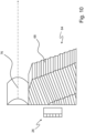
- Figure 8 shows an arrangement of a first optical attachment 50, a tilted first light guide plate 28 and a first additional light source 26 as well as a first projection lens.
- the first light guide plate 28 is characterized by a uniformly curved transition from its emission and deflection sides into the lateral narrow sides 36 used to feed in the additional light.
- the narrow side 36 used to feed in the additional light is preferably located in the light entry plane of the optical attachment 76, 50.
- the additional light source(s) and the LEDs used to generate the headlight light distributions can be arranged on the same flat and rigid circuit board. This applies analogously to the Figures 9 and 10 .
- Figure 9 shows an arrangement with a light guide plate that is less high in the vertical direction than the light guide plate of the Figure 8
- the Figure 10 shows a further arrangement with a second light guide plate 64, which is less wide in the horizontal direction between right and left than the light guide plate of the Figure 8 , together with a projection lens system instead of a single first projection lens 24 or second projection lens 60.
- the light guide plate after the Figure 10 indicates at its transition between its radiation side and the side used for feeding in light. This also makes it possible to create narrow radiation sides, as the kinks require less space for a change in direction than curved transitions.
Landscapes
- Engineering & Computer Science (AREA)
- General Engineering & Computer Science (AREA)
- Physics & Mathematics (AREA)
- Microelectronics & Electronic Packaging (AREA)
- Optics & Photonics (AREA)
- Non-Portable Lighting Devices Or Systems Thereof (AREA)
Claims (11)
- Phare de véhicule automobile (10) comportant un premier module de lumière de projection (14) qui présente une première source de lumière à semi-conducteurs (22), une première lentille de projection (24) et une première source de lumière supplémentaire (26) ainsi qu'une première plaque de guidage de lumière (28), dans lequel la première lentille de projection (24) présente un premier axe optique (30) et une première surface d'entrée de lumière (32) qui peut être éclairée par la première source de lumière supplémentaire (26) à travers la première plaque de guidage de lumière (28), dans lequel la première source de lumière supplémentaire (26) est disposée sur un côté étroit (36) de la première plaque de guidage de lumière (28) de sorte que de la lumière provenant de la première source de lumière supplémentaire (26) entre dans la première plaque de guidage de lumière (28) transversalement au premier axe optique (30) et la première plaque de guidage de lumière (28) présente un côté de rayonnement avant (38) tourné vers la première lentille de projection (24) et un premier côté de déviation arrière (40) opposé au premier côté de rayonnement avant (38) ainsi qu'une première partie (42) située plus près du premier axe optique (30) et une seconde partie (44) située plus loin du premier axe optique (30), dans lequel la première plaque de guidage de lumière (28) est disposée dans une position inclinée dans laquelle la première partie (42) de la première plaque de guidage de lumière (28) se trouve plus à l'écart de la première lentille de projection (24) le long du premier axe optique (30) que la seconde partie (44) de la première plaque de guidage de lumière (28), caractérisé en ce que, sur des structures de déviation disposées dans le premier côté de déviation arrière (40) de la première plaque de guidage de lumière (28), la lumière supplémentaire (34) est déviée de manière raide vers le premier côté de rayonnement avant (38) de la première plaque de guidage de lumière (28) de sorte qu'elle y sort en étant répartie uniformément, et en ce que la lumière supplémentaire (34) sortie est diffusée par des structures de diffusion (52) disposées dans le premier côté de rayonnement avant (38) au moins dans la direction verticale de sorte qu'elle éclaire la première surface d'entrée de lumière (32) de la première lentille de projection (24) en étant répartie uniformément.
- Phare de véhicule automobile (10) selon la revendication 1,
caractérisé en ce que le premier module de lumière de projection (14) est un module de feu de route. - Phare de véhicule automobile (10) selon la revendication 1,
caractérisé par un second module de lumière de projection (16) qui présente une seconde source de lumière à semi-conducteurs (74), une seconde lentille de projection (60) et une seconde source de lumière supplémentaire (62) ainsi qu'une seconde plaque de guidage de lumière (64), dans lequel la seconde lentille de projection (60) présente un second axe optique (66) et une seconde surface d'entrée de lumière (54) qui peut être éclairée par la seconde source de lumière supplémentaire (62) à travers la seconde plaque de guidage de lumière (64), dans lequel la seconde source de lumière supplémentaire (62) est disposée sur un côté étroit de la seconde plaque de guidage de lumière (64) de sorte que de la lumière provenant de la seconde source de lumière supplémentaire (62) entre dans la seconde plaque de guidage de lumière (64) transversalement au second axe optique (66) et la seconde plaque de guidage de lumière (64) présente un second côté de rayonnement avant (68) tourné vers la seconde lentille de projection (60) et un second côté de déviation arrière (70) opposé au second côté de rayonnement avant (68) ainsi qu'une première partie (43) située plus près du second axe optique (66) et une seconde partie (45) située plus loin du second axe optique (66), et en ce que la seconde plaque de guidage de lumière (64) est disposée dans une position inclinée dans laquelle la première partie (43) de la seconde plaque de guidage de lumière (64) se trouve plus à l'écart de la seconde lentille de projection (60) le long du second axe optique (66) que la seconde partie (45) de la seconde plaque de guidage de lumière (64). - Phare de véhicule automobile (10) selon la revendication 3,
caractérisé en ce que le second module de lumière de projection (16) présente un cache-miroir (72) s'étendant de l'arrière vers l'avant dans le phare de véhicule automobile (10) et en ce que la seconde plaque de guidage de lumière (64) est disposée en dessous du cache-miroir (72). - Phare de véhicule automobile (10) selon la revendication 3,
caractérisé en ce que la première plaque de guidage de lumière (28) et/ou la seconde plaque de guidage de lumière (64) présentent au moins une zone colorée. - Phare de véhicule automobile (10) selon la revendication 5,
caractérisé en ce que la zone colorée est une zone d'entrée de lumière de la plaque de guidage de lumière par ailleurs transparente et incolore. - Phare de véhicule automobile (10) selon la revendication 5,
caractérisé en ce que la zone colorée est une zone d'entrée de lumière revêtue de couleur de la plaque de guidage de lumière par ailleurs incolore. - Phare de véhicule automobile (10) selon l'une des revendications précédentes, caractérisé en ce que la couleur de la lumière de la première source de lumière supplémentaire (26) est invariable et est différente de la couleur de la lumière d'un feu de route et/ou d'un feu de croisement.
- Phare de véhicule automobile (10) selon l'une des revendications 3 à 7, caractérisé en ce que la couleur de la lumière de la première source de lumière supplémentaire (26) et/ou de la seconde source de lumière supplémentaire (62) est variable de manière commandée et peut être différente de la couleur de la lumière d'un feu de route et/ou d'un feu de croisement.
- Phare de véhicule automobile (10) selon la revendication 9,
caractérisé en ce que la première source de lumière supplémentaire (26) et/ou la seconde source de lumière supplémentaire (62) présentent des diodes électroluminescentes (R, G, B) de différentes couleurs et pouvant être commandées individuellement. - Phare de véhicule automobile (10) selon la revendication 10,
caractérisé en ce que les diodes électroluminescentes de différentes couleurs et pouvant être commandées individuellement comprennent une diode électroluminescente émettant de la lumière rouge (R), une diode électroluminescente émettant de la lumière verte (G) et une diode électroluminescente émettant de la lumière bleue (B).
Applications Claiming Priority (1)
| Application Number | Priority Date | Filing Date | Title |
|---|---|---|---|
| DE102020119195.2A DE102020119195A1 (de) | 2020-07-21 | 2020-07-21 | Kraftfahrzeugscheinwerfer mit Projektionslichtmodulen |
Publications (2)
| Publication Number | Publication Date |
|---|---|
| EP3943809A1 EP3943809A1 (fr) | 2022-01-26 |
| EP3943809B1 true EP3943809B1 (fr) | 2025-01-15 |
Family
ID=76999661
Family Applications (1)
| Application Number | Title | Priority Date | Filing Date |
|---|---|---|---|
| EP21186577.9A Active EP3943809B1 (fr) | 2020-07-21 | 2021-07-20 | Phares de véhicule automobile pourvus de modules de projection |
Country Status (2)
| Country | Link |
|---|---|
| EP (1) | EP3943809B1 (fr) |
| DE (1) | DE102020119195A1 (fr) |
Families Citing this family (1)
| Publication number | Priority date | Publication date | Assignee | Title |
|---|---|---|---|---|
| CZ202272A3 (cs) * | 2022-02-15 | 2023-08-23 | Hella Autotechnik Nova, S.R.O. | Přední světlomet pro automobil |
Family Cites Families (8)
| Publication number | Priority date | Publication date | Assignee | Title |
|---|---|---|---|---|
| DE102010046021A1 (de) * | 2010-09-18 | 2012-03-22 | Automotive Lighting Reutlingen Gmbh | Kraftfahrzeugscheinwerfer mit einem Mehrfunktions-Projektionsmodul |
| DE102011076621B4 (de) | 2011-05-27 | 2017-03-02 | Automotive Lighting Reutlingen Gmbh | Beleuchtungseinrichtung für ein Kraftfahrzeug |
| JP2012256491A (ja) | 2011-06-08 | 2012-12-27 | Stanley Electric Co Ltd | 車両用灯具ユニット |
| EP3379139B1 (fr) * | 2015-11-20 | 2025-01-22 | Koito Manufacturing Co., Ltd. | Unité de luminaire |
| KR102405436B1 (ko) * | 2017-09-28 | 2022-06-07 | 에스엘 주식회사 | 차량용 램프 |
| CN207674345U (zh) * | 2018-01-19 | 2018-07-31 | 上海小糸车灯有限公司 | 聚光器和车灯模组 |
| FR3079597B1 (fr) * | 2018-03-28 | 2020-10-02 | Valeo Vision | Module optique pour vehicule automobile |
| DE102018113768A1 (de) | 2018-06-08 | 2019-12-12 | Automotive Lighting Reutlingen Gmbh | Kraftfahrzeugscheinwerfer mit mindestens zwei Lichtmodulen |
-
2020
- 2020-07-21 DE DE102020119195.2A patent/DE102020119195A1/de active Pending
-
2021
- 2021-07-20 EP EP21186577.9A patent/EP3943809B1/fr active Active
Also Published As
| Publication number | Publication date |
|---|---|
| DE102020119195A1 (de) | 2022-01-27 |
| EP3943809A1 (fr) | 2022-01-26 |
Similar Documents
| Publication | Publication Date | Title |
|---|---|---|
| DE69205858T2 (de) | Verbessertes zentralisiertes Beleuchtungssystem für Kraftfahrzeuge. | |
| EP2799761B1 (fr) | Module d'éclairage de phare de véhicule automobile | |
| DE10237262B4 (de) | Fahrzeugleuchte mit einer LED-Lichtquelle und gleichmäßiger Helligkeit | |
| DE102010056313C5 (de) | Beleuchtungseinrichtung eines Kraftfahrzeugs | |
| EP2784376B1 (fr) | Lampe de véhicule automobile pour fonctions d'éclairage dynamiques | |
| DE10239280B4 (de) | LED-Fahrzeugleuchte | |
| DE102017206325A1 (de) | Fahrzeugleuchte und Fahrzeug mit einer solchen | |
| DE112017004923B4 (de) | Lichtführungselement, Lichtführungseinheit und Beleuchtungsvorrichtung | |
| DE102017105838B4 (de) | Beleuchtungseinrichtung eines Kraftfahrzeugs mit einer Lichtleiteranordnung | |
| DE102017205010A1 (de) | Fahrzeugleuchte und Fahrzeug mit einer solchen | |
| EP2754948A2 (fr) | Module lumineux pour un phare de véhicule automobile conçu pour produire des distributions lumineuses en forme de bande | |
| EP2338732A1 (fr) | Dispositif d'éclairage de véhicule automobile doté d'un guide de lumière et de sources lumineuses de différentes couleurs | |
| EP3699486B1 (fr) | Phare pourvu d'une pluralité de sources lumineuses à semi-conducteurs et d'un champ optique primaire en une pièce | |
| DE102018113768A1 (de) | Kraftfahrzeugscheinwerfer mit mindestens zwei Lichtmodulen | |
| EP3210827A1 (fr) | Feu de véhicule | |
| DE102011014113A1 (de) | Transparente Optik einer Beleuchtungseinrichtung eines Kraftfahrzeugs | |
| EP3943809B1 (fr) | Phares de véhicule automobile pourvus de modules de projection | |
| EP2500754B1 (fr) | Dispositif d'éclairage pour véhicule automobile | |
| DE102022107679B4 (de) | Leuchte für ein Fahrzeug | |
| DE4112194C2 (de) | Kraftfahrzeugscheinwerfereinheit | |
| DE102015204735B4 (de) | Lichtleiterelement einer Kraftfahrzeug-Beleuchtungseinrichtung und Kraftfahrzeug-Beleuchtungseinrichtung mit einem solchen Lichtleiterelement | |
| DE112019004405T5 (de) | Optisches Element einer Fahrzeugleuchte, Fahrzeugleuchtenmodul, Fahrzeug-Scheinwerfer und Fahrzeug | |
| DE102013210257A1 (de) | Vorsatzoptik für eine Lichtquelle | |
| DE4420889B4 (de) | Beleuchtungsvorrichtung für Fahrzeuge | |
| DE102011087309A1 (de) | Leuchtvorrichtung |
Legal Events
| Date | Code | Title | Description |
|---|---|---|---|
| PUAI | Public reference made under article 153(3) epc to a published international application that has entered the european phase |
Free format text: ORIGINAL CODE: 0009012 |
|
| STAA | Information on the status of an ep patent application or granted ep patent |
Free format text: STATUS: THE APPLICATION HAS BEEN PUBLISHED |
|
| AK | Designated contracting states |
Kind code of ref document: A1 Designated state(s): AL AT BE BG CH CY CZ DE DK EE ES FI FR GB GR HR HU IE IS IT LI LT LU LV MC MK MT NL NO PL PT RO RS SE SI SK SM TR |
|
| STAA | Information on the status of an ep patent application or granted ep patent |
Free format text: STATUS: REQUEST FOR EXAMINATION WAS MADE |
|
| 17P | Request for examination filed |
Effective date: 20220726 |
|
| RBV | Designated contracting states (corrected) |
Designated state(s): AL AT BE BG CH CY CZ DE DK EE ES FI FR GB GR HR HU IE IS IT LI LT LU LV MC MK MT NL NO PL PT RO RS SE SI SK SM TR |
|
| GRAP | Despatch of communication of intention to grant a patent |
Free format text: ORIGINAL CODE: EPIDOSNIGR1 |
|
| STAA | Information on the status of an ep patent application or granted ep patent |
Free format text: STATUS: GRANT OF PATENT IS INTENDED |
|
| INTG | Intention to grant announced |
Effective date: 20240809 |
|
| GRAS | Grant fee paid |
Free format text: ORIGINAL CODE: EPIDOSNIGR3 |
|
| GRAA | (expected) grant |
Free format text: ORIGINAL CODE: 0009210 |
|
| STAA | Information on the status of an ep patent application or granted ep patent |
Free format text: STATUS: THE PATENT HAS BEEN GRANTED |
|
| AK | Designated contracting states |
Kind code of ref document: B1 Designated state(s): AL AT BE BG CH CY CZ DE DK EE ES FI FR GB GR HR HU IE IS IT LI LT LU LV MC MK MT NL NO PL PT RO RS SE SI SK SM TR |
|
| RAP3 | Party data changed (applicant data changed or rights of an application transferred) |
Owner name: MARELLI GERMANY GMBH |
|
| REG | Reference to a national code |
Ref country code: CH Ref legal event code: EP Ref country code: GB Ref legal event code: FG4D Free format text: NOT ENGLISH |
|
| REG | Reference to a national code |
Ref country code: DE Ref legal event code: R096 Ref document number: 502021006419 Country of ref document: DE |
|
| REG | Reference to a national code |
Ref country code: CH Ref legal event code: PK Free format text: BERICHTIGUNGEN |
|
| REG | Reference to a national code |
Ref country code: IE Ref legal event code: FG4D Free format text: LANGUAGE OF EP DOCUMENT: GERMAN |
|
| REG | Reference to a national code |
Ref country code: CH Ref legal event code: PK Free format text: BERICHTIGUNGEN |
|
| RIN2 | Information on inventor provided after grant (corrected) |
Inventor name: ARTIGOU, XAVIER Inventor name: AUSTERSCHULTE, ARMIN Inventor name: ZIEGLER, PATRICK Inventor name: STRAHL-SCHAEFER, STEPHANIE Inventor name: LOEHLE, ANJA Inventor name: VOGT, HENNING |
|
| RIN2 | Information on inventor provided after grant (corrected) |
Inventor name: ARTIGOU, XAVIER Inventor name: AUSTERSCHULTE, ARMIN Inventor name: ZIEGLER, PATRICK Inventor name: STRAHL-SCHAEFER, STEPHANIE Inventor name: LOEHLE, ANJA Inventor name: DR. VOGT, HENNING |
|
| P01 | Opt-out of the competence of the unified patent court (upc) registered |
Free format text: CASE NUMBER: APP_7369/2025 Effective date: 20250213 |
|
| REG | Reference to a national code |
Ref country code: NL Ref legal event code: MP Effective date: 20250115 |
|
| PG25 | Lapsed in a contracting state [announced via postgrant information from national office to epo] |
Ref country code: NL Free format text: LAPSE BECAUSE OF FAILURE TO SUBMIT A TRANSLATION OF THE DESCRIPTION OR TO PAY THE FEE WITHIN THE PRESCRIBED TIME-LIMIT Effective date: 20250115 |
|
| PG25 | Lapsed in a contracting state [announced via postgrant information from national office to epo] |
Ref country code: RS Free format text: LAPSE BECAUSE OF FAILURE TO SUBMIT A TRANSLATION OF THE DESCRIPTION OR TO PAY THE FEE WITHIN THE PRESCRIBED TIME-LIMIT Effective date: 20250415 |
|
| PG25 | Lapsed in a contracting state [announced via postgrant information from national office to epo] |
Ref country code: FI Free format text: LAPSE BECAUSE OF FAILURE TO SUBMIT A TRANSLATION OF THE DESCRIPTION OR TO PAY THE FEE WITHIN THE PRESCRIBED TIME-LIMIT Effective date: 20250115 |
|
| PG25 | Lapsed in a contracting state [announced via postgrant information from national office to epo] |
Ref country code: PL Free format text: LAPSE BECAUSE OF FAILURE TO SUBMIT A TRANSLATION OF THE DESCRIPTION OR TO PAY THE FEE WITHIN THE PRESCRIBED TIME-LIMIT Effective date: 20250115 |
|
| PG25 | Lapsed in a contracting state [announced via postgrant information from national office to epo] |
Ref country code: ES Free format text: LAPSE BECAUSE OF FAILURE TO SUBMIT A TRANSLATION OF THE DESCRIPTION OR TO PAY THE FEE WITHIN THE PRESCRIBED TIME-LIMIT Effective date: 20250115 |
|
| REG | Reference to a national code |
Ref country code: LT Ref legal event code: MG9D |
|
| PG25 | Lapsed in a contracting state [announced via postgrant information from national office to epo] |
Ref country code: IS Free format text: LAPSE BECAUSE OF FAILURE TO SUBMIT A TRANSLATION OF THE DESCRIPTION OR TO PAY THE FEE WITHIN THE PRESCRIBED TIME-LIMIT Effective date: 20250515 Ref country code: NO Free format text: LAPSE BECAUSE OF FAILURE TO SUBMIT A TRANSLATION OF THE DESCRIPTION OR TO PAY THE FEE WITHIN THE PRESCRIBED TIME-LIMIT Effective date: 20250415 |
|
| PG25 | Lapsed in a contracting state [announced via postgrant information from national office to epo] |
Ref country code: HR Free format text: LAPSE BECAUSE OF FAILURE TO SUBMIT A TRANSLATION OF THE DESCRIPTION OR TO PAY THE FEE WITHIN THE PRESCRIBED TIME-LIMIT Effective date: 20250115 |
|
| PG25 | Lapsed in a contracting state [announced via postgrant information from national office to epo] |
Ref country code: PT Free format text: LAPSE BECAUSE OF FAILURE TO SUBMIT A TRANSLATION OF THE DESCRIPTION OR TO PAY THE FEE WITHIN THE PRESCRIBED TIME-LIMIT Effective date: 20250515 Ref country code: LV Free format text: LAPSE BECAUSE OF FAILURE TO SUBMIT A TRANSLATION OF THE DESCRIPTION OR TO PAY THE FEE WITHIN THE PRESCRIBED TIME-LIMIT Effective date: 20250115 |
|
| PGFP | Annual fee paid to national office [announced via postgrant information from national office to epo] |
Ref country code: FR Payment date: 20250620 Year of fee payment: 5 |
|
| PG25 | Lapsed in a contracting state [announced via postgrant information from national office to epo] |
Ref country code: GR Free format text: LAPSE BECAUSE OF FAILURE TO SUBMIT A TRANSLATION OF THE DESCRIPTION OR TO PAY THE FEE WITHIN THE PRESCRIBED TIME-LIMIT Effective date: 20250416 Ref country code: BG Free format text: LAPSE BECAUSE OF FAILURE TO SUBMIT A TRANSLATION OF THE DESCRIPTION OR TO PAY THE FEE WITHIN THE PRESCRIBED TIME-LIMIT Effective date: 20250115 |
|
| PG25 | Lapsed in a contracting state [announced via postgrant information from national office to epo] |
Ref country code: SE Free format text: LAPSE BECAUSE OF FAILURE TO SUBMIT A TRANSLATION OF THE DESCRIPTION OR TO PAY THE FEE WITHIN THE PRESCRIBED TIME-LIMIT Effective date: 20250115 |
|
| PG25 | Lapsed in a contracting state [announced via postgrant information from national office to epo] |
Ref country code: SM Free format text: LAPSE BECAUSE OF FAILURE TO SUBMIT A TRANSLATION OF THE DESCRIPTION OR TO PAY THE FEE WITHIN THE PRESCRIBED TIME-LIMIT Effective date: 20250115 |
|
| PG25 | Lapsed in a contracting state [announced via postgrant information from national office to epo] |
Ref country code: DK Free format text: LAPSE BECAUSE OF FAILURE TO SUBMIT A TRANSLATION OF THE DESCRIPTION OR TO PAY THE FEE WITHIN THE PRESCRIBED TIME-LIMIT Effective date: 20250115 |
|
| PG25 | Lapsed in a contracting state [announced via postgrant information from national office to epo] |
Ref country code: IT Free format text: LAPSE BECAUSE OF FAILURE TO SUBMIT A TRANSLATION OF THE DESCRIPTION OR TO PAY THE FEE WITHIN THE PRESCRIBED TIME-LIMIT Effective date: 20250115 |
|
| REG | Reference to a national code |
Ref country code: DE Ref legal event code: R097 Ref document number: 502021006419 Country of ref document: DE |
|
| PGFP | Annual fee paid to national office [announced via postgrant information from national office to epo] |
Ref country code: AT Payment date: 20251020 Year of fee payment: 5 |
|
| PG25 | Lapsed in a contracting state [announced via postgrant information from national office to epo] |
Ref country code: CZ Free format text: LAPSE BECAUSE OF FAILURE TO SUBMIT A TRANSLATION OF THE DESCRIPTION OR TO PAY THE FEE WITHIN THE PRESCRIBED TIME-LIMIT Effective date: 20250115 Ref country code: EE Free format text: LAPSE BECAUSE OF FAILURE TO SUBMIT A TRANSLATION OF THE DESCRIPTION OR TO PAY THE FEE WITHIN THE PRESCRIBED TIME-LIMIT Effective date: 20250115 |
|
| PG25 | Lapsed in a contracting state [announced via postgrant information from national office to epo] |
Ref country code: RO Free format text: LAPSE BECAUSE OF FAILURE TO SUBMIT A TRANSLATION OF THE DESCRIPTION OR TO PAY THE FEE WITHIN THE PRESCRIBED TIME-LIMIT Effective date: 20250115 |
|
| PG25 | Lapsed in a contracting state [announced via postgrant information from national office to epo] |
Ref country code: SK Free format text: LAPSE BECAUSE OF FAILURE TO SUBMIT A TRANSLATION OF THE DESCRIPTION OR TO PAY THE FEE WITHIN THE PRESCRIBED TIME-LIMIT Effective date: 20250115 |
|
| PLBE | No opposition filed within time limit |
Free format text: ORIGINAL CODE: 0009261 |
|
| STAA | Information on the status of an ep patent application or granted ep patent |
Free format text: STATUS: NO OPPOSITION FILED WITHIN TIME LIMIT |
|
| REG | Reference to a national code |
Ref country code: CH Ref legal event code: L10 Free format text: ST27 STATUS EVENT CODE: U-0-0-L10-L00 (AS PROVIDED BY THE NATIONAL OFFICE) Effective date: 20251126 |
|
| 26N | No opposition filed |
Effective date: 20251016 |
|
| REG | Reference to a national code |
Ref country code: CH Ref legal event code: H13 Free format text: ST27 STATUS EVENT CODE: U-0-0-H10-H13 (AS PROVIDED BY THE NATIONAL OFFICE) Effective date: 20260224 |
|
| PG25 | Lapsed in a contracting state [announced via postgrant information from national office to epo] |
Ref country code: LU Free format text: LAPSE BECAUSE OF NON-PAYMENT OF DUE FEES Effective date: 20250720 |
|
| GBPC | Gb: european patent ceased through non-payment of renewal fee |
Effective date: 20250720 |
|
| REG | Reference to a national code |
Ref country code: BE Ref legal event code: MM Effective date: 20250731 |
|
| PG25 | Lapsed in a contracting state [announced via postgrant information from national office to epo] |
Ref country code: GB Free format text: LAPSE BECAUSE OF NON-PAYMENT OF DUE FEES Effective date: 20250720 |
|
| PGFP | Annual fee paid to national office [announced via postgrant information from national office to epo] |
Ref country code: DE Payment date: 20260115 Year of fee payment: 5 |
|
| PG25 | Lapsed in a contracting state [announced via postgrant information from national office to epo] |
Ref country code: BE Free format text: LAPSE BECAUSE OF NON-PAYMENT OF DUE FEES Effective date: 20250731 |
|
| PG25 | Lapsed in a contracting state [announced via postgrant information from national office to epo] |
Ref country code: CH Free format text: LAPSE BECAUSE OF NON-PAYMENT OF DUE FEES Effective date: 20250731 |