EP3944400A1 - Procédé de simulation, dispositif de simulation et programme informatique - Google Patents
Procédé de simulation, dispositif de simulation et programme informatique Download PDFInfo
- Publication number
- EP3944400A1 EP3944400A1 EP20772540.9A EP20772540A EP3944400A1 EP 3944400 A1 EP3944400 A1 EP 3944400A1 EP 20772540 A EP20772540 A EP 20772540A EP 3944400 A1 EP3944400 A1 EP 3944400A1
- Authority
- EP
- European Patent Office
- Prior art keywords
- power storage
- storage device
- simulation
- outside
- simulation condition
- Prior art date
- Legal status (The legal status is an assumption and is not a legal conclusion. Google has not performed a legal analysis and makes no representation as to the accuracy of the status listed.)
- Pending
Links
Images



Classifications
-
- H—ELECTRICITY
- H01—ELECTRIC ELEMENTS
- H01M—PROCESSES OR MEANS, e.g. BATTERIES, FOR THE DIRECT CONVERSION OF CHEMICAL ENERGY INTO ELECTRICAL ENERGY
- H01M10/00—Secondary cells; Manufacture thereof
- H01M10/42—Methods or arrangements for servicing or maintenance of secondary cells or secondary half-cells
-
- G—PHYSICS
- G06—COMPUTING OR CALCULATING; COUNTING
- G06F—ELECTRIC DIGITAL DATA PROCESSING
- G06F30/00—Computer-aided design [CAD]
- G06F30/20—Design optimisation, verification or simulation
-
- G—PHYSICS
- G06—COMPUTING OR CALCULATING; COUNTING
- G06F—ELECTRIC DIGITAL DATA PROCESSING
- G06F30/00—Computer-aided design [CAD]
- G06F30/30—Circuit design
- G06F30/36—Circuit design at the analogue level
- G06F30/367—Design verification, e.g. using simulation, simulation program with integrated circuit emphasis [SPICE], direct methods or relaxation methods
-
- G—PHYSICS
- G06—COMPUTING OR CALCULATING; COUNTING
- G06F—ELECTRIC DIGITAL DATA PROCESSING
- G06F30/00—Computer-aided design [CAD]
- G06F30/30—Circuit design
- G06F30/39—Circuit design at the physical level
- G06F30/398—Design verification or optimisation, e.g. using design rule check [DRC], layout versus schematics [LVS] or finite element methods [FEM]
-
- H—ELECTRICITY
- H01—ELECTRIC ELEMENTS
- H01M—PROCESSES OR MEANS, e.g. BATTERIES, FOR THE DIRECT CONVERSION OF CHEMICAL ENERGY INTO ELECTRICAL ENERGY
- H01M10/00—Secondary cells; Manufacture thereof
- H01M10/42—Methods or arrangements for servicing or maintenance of secondary cells or secondary half-cells
- H01M10/48—Accumulators combined with arrangements for measuring, testing or indicating the condition of cells, e.g. the level or density of the electrolyte
-
- G—PHYSICS
- G06—COMPUTING OR CALCULATING; COUNTING
- G06F—ELECTRIC DIGITAL DATA PROCESSING
- G06F2119/00—Details relating to the type or aim of the analysis or the optimisation
- G06F2119/06—Power analysis or power optimisation
-
- G—PHYSICS
- G06—COMPUTING OR CALCULATING; COUNTING
- G06F—ELECTRIC DIGITAL DATA PROCESSING
- G06F2119/00—Details relating to the type or aim of the analysis or the optimisation
- G06F2119/08—Thermal analysis or thermal optimisation
-
- H—ELECTRICITY
- H01—ELECTRIC ELEMENTS
- H01M—PROCESSES OR MEANS, e.g. BATTERIES, FOR THE DIRECT CONVERSION OF CHEMICAL ENERGY INTO ELECTRICAL ENERGY
- H01M10/00—Secondary cells; Manufacture thereof
- H01M10/60—Heating or cooling; Temperature control
- H01M10/63—Control systems
- H01M10/633—Control systems characterised by algorithms, flow charts, software details or the like
-
- Y—GENERAL TAGGING OF NEW TECHNOLOGICAL DEVELOPMENTS; GENERAL TAGGING OF CROSS-SECTIONAL TECHNOLOGIES SPANNING OVER SEVERAL SECTIONS OF THE IPC; TECHNICAL SUBJECTS COVERED BY FORMER USPC CROSS-REFERENCE ART COLLECTIONS [XRACs] AND DIGESTS
- Y02—TECHNOLOGIES OR APPLICATIONS FOR MITIGATION OR ADAPTATION AGAINST CLIMATE CHANGE
- Y02E—REDUCTION OF GREENHOUSE GAS [GHG] EMISSIONS, RELATED TO ENERGY GENERATION, TRANSMISSION OR DISTRIBUTION
- Y02E60/00—Enabling technologies; Technologies with a potential or indirect contribution to GHG emissions mitigation
- Y02E60/10—Energy storage using batteries
Definitions
- the present invention relates to a computer-implemented simulation method, a simulation device, and a computer program.
- MBD model-based development
- Patent Document 1 JP-A-11-14507
- model-based development for example, a case where thermal safety is simulated for a specific power storage device that is one of development elements. It is necessary to set various conditions according to a physical phenomenon or a chemical phenomenon occurring inside the power storage device. In an event related to safety of the power storage device, a plurality of physical phenomena such as chemical reaction, heat transfer, current, electrochemistry, and fluid dynamics are related to each other, and a mechanism and a physical property value are often unknown. For this reason, it is difficult for a technician who is not familiar with batteries to simulate the safety of the power storage device. However, in consideration of the recent remarkable development progress of electric vehicles, renewable energy, smart grids, and the like, there is high expectation for a high-performance and highly safe power storage device, and safety design using simulation is significant.
- the present invention has been made in view of such circumstances, and an object of the present invention is to provide a simulation method, a simulation device, and a computer program that enable even a technician who is not familiar with batteries to easily simulate a thermal phenomenon of a power storage device.
- a simulation method receives a simulation condition related to a power storage device, and calculates short-circuit current based on the received simulation condition to simulate a thermal phenomenon from the power storage device to the outside.
- a simulation device includes a reception unit that receives a simulation condition related to a power storage device, a simulation execution unit that calculates short-circuit current based on the received simulation condition to simulate a thermal phenomenon from the power storage device to outside, and an output unit that outputs a simulation result by the simulation execution unit or a simulation program based on the simulation condition.
- a computer program is a computer program for causing a computer to execute processing of presenting a user interface that receives a simulation condition related to a power storage device, and calculating short-circuit current based on the received simulation condition to simulate a thermal phenomenon from the power storage device to the outside.
- a simulation method receives a simulation condition related to a power storage device, and calculates short-circuit current based on the received simulation condition to simulate a thermal phenomenon from the power storage device to the outside.
- the outside may be, for example, a container that houses a power storage device or a power storage system including a plurality of power storage devices, a storage battery storage unit of a vehicle, or a space outside a building that houses a power storage device.
- a thermal phenomenon from the power storage device to the outside can be simulated based on the received simulation condition.
- the thermal phenomenon from the power storage device to the outside includes, for example, an exothermic phenomenon due to Joule heating and a material decomposition reaction accompanying an internal short-circuit and an external short-circuit, an exothermic phenomenon due to a material decomposition reaction in a case where the power storage device is heated from the outside, and gas generation accompanying heat generation of the power storage device.
- a heat generation rate of the power storage device, a gas generation rate, and the like are calculated based on a simulation condition.
- the simulation method may receive a simulation condition transmitted from an external terminal after user authentication using the external terminal, and transmit an execution result of simulation based on the received simulation condition to the external terminal. According to this configuration, even in a case where the user is not familiar with a theory representing behavior of the power storage device, a simulation result or a simulation program of a thermal phenomenon appearing outside the power storage device can be provided to the user only by receiving of a simulation condition.
- the simulation condition may include an occurrence location of an internal short-circuit in the power storage device, and the simulation method may simulate the thermal phenomenon accompanying the internal short-circuit.
- the simulation condition may further include information related to a resistance value of a short circuit portion.
- the information related to the resistance value of the short circuit portion may include a name (for example, nickel and iron) and a shape (for example, a circle, a square, and their sizes) of a substance that causes an internal short-circuit, a mode of the internal short-circuit (for example, crash, nail penetration, foreign object contamination), and the like, and it is preferable that the resistance value of the short circuit portion be able to be calculated from the information.
- the information related to the resistance value of the short circuit portion may directly indicate a resistance value of a short circuit portion, such as contact resistance between the short circuit portion and a member constituting the power storage device (for example, positive electrode current collecting foil). According to this configuration, it is possible to simulate a thermal phenomenon accompanying an internal short-circuit at different occurrence locations by providing an occurrence location of the internal short-circuit.
- the power storage device may include a wound electrode assembly, and the simulation method may calculate short-circuit current in a state where the wound electrode assembly is virtually developed. According to this configuration, since short-circuit current is calculated in consideration of a structure of a wound cell, a thermal phenomenon according to a through short circuit or a partial short circuit can be accurately simulated.
- the simulation condition may include information related to a resistance value in an external short-circuit of the power storage device, and the simulation method may simulate the thermal phenomenon accompanying the external short-circuit. According to this configuration, a thermal phenomenon accompanying an external short-circuit can be simulated by providing information related to a resistance value in the external short-circuit.
- a simulation method receives a simulation condition related to a power storage device, the simulation condition including a heating location when the power storage device is heated from the outside, and simulates a thermal phenomenon from the power storage device to the outside accompanying heating of the power storage device based on the received simulation condition.
- the simulation condition may further include an amount of heat of external heating.
- the simulation condition may further include an environmental temperature. According to this configuration, it is possible to simulate a thermal phenomenon accompanying heating by providing a heating location when the power storage device is heated from the outside.
- the simulation method may simulate the thermal phenomenon by coupled analysis of an electrochemical reaction in the power storage device and an exothermic reaction in a material decomposition reaction of the power storage device. Since the exothermic reaction and Joule heating of the battery are not independent physical phenomena, and proceed while being correlated with each other through physical phenomena such as heat transfer, it is possible to simulate the behavior of the battery by accurately reflecting a phenomenon occurring inside the battery by performing coupled analysis.
- the simulation method may formulate a relationship between a temperature and a calorific value obtained by differential thermal analysis of the power storage device, and calculates a heat generation rate in a material decomposition reaction of the power storage device based on a relational expression between a temperature and a calorific value obtained by formulation. According to this configuration, since the relationship between a temperature and a calorific value obtained by differential thermal analysis is formulated, it is not necessary to convert the relationship between a temperature and a calorific value into a relationship between time and a calorific value.
- a simulation method receives a simulation condition related to a power storage device, and simulates generation of gas accompanying a material decomposition reaction of the power storage device based on the received simulation condition.
- a simulation condition related to a power storage device receives a simulation condition related to a power storage device, and simulates generation of gas accompanying a material decomposition reaction of the power storage device based on the received simulation condition.
- an event such as an internal short-circuit occurs in the power storage device and a safety mechanism does not function well, there is possibility that the material decomposition reaction progresses and gas at a high temperature is ejected from the inside of the power storage device.
- gas generation accompanying a material decomposition reaction can be simulated.
- the simulation method may calculate at least one of a generation rate of the gas and a generation rate of an amount of heat based on a reaction rate of the material decomposition reaction.
- the generation rate of the gas may be calculated so as to be proportional to the reaction rate of the material decomposition reaction. According to this configuration, at least one of the generation rate of gas and the generation rate of an amount of heat is calculated based on the reaction rate of the material decomposition reaction.
- a simulation device includes a reception unit that receives a simulation condition related to a power storage device, a simulation execution unit that calculates short-circuit current based on the received simulation condition to simulate a thermal phenomenon from the power storage device to outside, and an output unit that outputs a simulation result by the simulation execution unit or a simulation program based on the simulation condition.
- a thermal phenomenon from the power storage device to the outside can be simulated based on the received simulation condition.
- the thermal phenomenon from the power storage device to the outside includes, for example, an exothermic phenomenon due to a material decomposition reaction accompanying an internal short-circuit and an external short-circuit, an exothermic phenomenon due to a material decomposition reaction in a case where the power storage device is heated from the outside, and gas generation accompanying heat generation of the power storage device.
- a heat generation rate of the power storage device, a gas generation rate, and the like are calculated based on a simulation condition.
- a computer program causes a computer to execute processing of presenting a user interface that receives a simulation condition related to a power storage device, and calculating short-circuit current based on the received simulation condition to simulate a thermal phenomenon from the power storage device to the outside.
- a thermal phenomenon from the power storage device to the outside can be simulated based on the received simulation condition.
- the thermal phenomenon from the power storage device to the outside includes, for example, an exothermic phenomenon due to a material decomposition reaction accompanying an internal short-circuit and an external short-circuit, an exothermic phenomenon due to a material decomposition reaction in a case where the power storage device is heated from the outside, and gas generation accompanying heat generation of the power storage device.
- a heat generation rate of the power storage device, a gas generation rate, and the like are calculated based on a simulation condition.
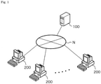
- Fig. 1 is a schematic diagram describing an overall configuration of a simulation system according to the present embodiment.
- the simulation system according to the present embodiment includes a server device 100 and a client device 200 communicably connected to each other via a communication network N.
- the server device 100 simulates a thermal phenomenon appearing in the outside from the power storage device and provides a simulation result to the client device 200.
- the power storage device of a simulation target includes an energy storage device (cell) such as a lead-acid battery, a secondary battery such as a lithium ion battery, or a capacitor.
- the power storage device of a simulation target may include a module in which a plurality of cells are connected in series, a bank (series connection battery group) in which a plurality of modules are connected in series, a domain (parallel connection battery group) in which a plurality of banks are connected in parallel, and the like.
- the client device 200 is a terminal device such as a personal computer, a smartphone, or a tablet terminal used by the user.
- Software (application program) for accessing the server device 100 is installed in the client device 200.
- the server device 100 performs, for example, user authentication based on a user ID and a password when receiving an access from the client device 200, and provides an appropriate service to the client device 200 in a case where the user authentication is successful.
- the server device 100 After the user authentication, the server device 100 according to the present embodiment transmits, to the client device 200, an interface screen for receiving various inputs by the user of the client device 200.
- the interface screen includes, for example, a reception screen for receiving a simulation condition.
- the server device 100 transmits a simulation result executed on the basis of the received condition to the client device 200.
- the simulation result transmitted from the server device 100 to the client device 200 includes data such as numerical data and a graph obtained as an execution result of a simulation.
- the simulation result transmitted from the server device 100 to the client device 200 may include a mathematical model obtained as an execution result of simulation or a simulation program based on a simulation condition.
- a simulation condition is received in the client device 200, and the received simulation condition and the like are transmitted to the server device 100 so that simulation is executed.
- the server device 100 may receive a simulation condition, execute simulation on the basis of the received simulation condition or the like, and display a simulation result on the server device 100.
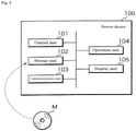
- Fig. 2 is a block diagram describing an internal configuration of the server device 100.
- the server device 100 includes a control unit 101, a storage unit 102, a communication unit 103, an operation unit 104, and a display unit 105.
- the control unit 101 includes a central processing unit (CPU), a read only memory (ROM), a random access memory (RAM), and the like.
- the CPU included in the control unit 101 loads various computer programs stored in the ROM or the storage unit 102 into the RAM and executes the programs so as to cause the entire device to function as the simulation device of the present application by.
- the server device 100 is merely an embodiment of the simulation device, and may be any information processing device communicably connected to the client device 200.
- the control unit 101 is not limited to the above configuration, and may be any processing circuit or arithmetic circuit including a plurality of CPUs, a multi-core CPU, a graphics processing unit (GPU), a microcomputer, a volatile or nonvolatile memory, and the like.
- the control unit 101 may have a function of a timer that measures elapsed time from when a measurement start instruction is given to when a measurement end instruction is given, a counter that counts the number, a clock that outputs date and time information, and the like.
- the storage unit 102 includes a storage device using a hard disk drive (HDD), a solid state drive (SSD), or the like.
- the storage unit 102 stores various computer programs executed by the control unit 101, data necessary for executing the computer programs, and the like.
- the computer program stored in the storage unit 102 includes a simulation program for simulating a thermal phenomenon appearing in the outside from the power storage device.
- the simulation program is, for example, execution binary.
- a theoretical equation that is a source of the simulation program is described by an algebraic equation or a differential equation representing a thermal phenomenon appearing in the outside from the power storage device.
- the simulation program may be a single computer program or a program group including a plurality of computer programs.
- the simulation program may be described by commercially available numerical analysis software or programming language such as MATLAB (registered trademark), Amesim (registered trademark), Twin Builder (registered trademark), MATLAB & Simulink (registered trademark), Simplorer (registered trademark), ANSYS (registered trademark), Abaqus (registered trademark), Modelica (registered trademark), VHDL-AMS (registered trademark), C language, C++, or Java (registered trademark).
- the numerical analysis software may be a circuit simulator referred to as 1D-CAE, or simulation such as a finite element method or a finite volume method by a 3D shape. A reduced-order model (ROM) based on these may be used.
- the program stored in the storage unit 102 may be provided by a non-transitory recording medium M in which the program is recorded in a readable manner.
- the recording medium M is, for example, a portable memory such as a CD-ROM, a universal serial bus (USB) memory, a secure digital (SD) card, a micro SD card, and a compact flash (registered trademark).
- the control unit 101 reads a program from the recording medium M using a reading device (not illustrated), and installs the read program in the storage unit 102.
- the program stored in the storage unit 102 may be provided by communication via the communication unit 103. In this case, the control unit 101 acquires the program through the communication unit 103 and installs the acquired program in the storage unit 102.
- the storage unit 102 may store a mathematical model obtained as a result of simulation.
- the mathematical model is, for example, an execution code executed by a programming language or numerical analysis software.
- the mathematical model may be definition information or a library file referred to by a programming language or numerical analysis software.
- the storage unit 102 may have a battery table in which information on the power storage device (for example, a secondary battery) is stored in association with a user ID.
- Fig. 3 is a conceptual diagram illustrating an example of the battery table.
- the battery table stores, for example, a battery ID for identifying a battery, a user ID for identifying the user, and battery information in association with each other.
- the battery information registered in the battery table includes, for example, information on the positive electrode and the negative electrode, information on the electrolyte solution, information on the current collector, and the like.
- the information on the positive electrode and the negative electrode is information such as an active material name, thickness, width, depth, and open circuit potential of the positive electrode and the negative electrode.
- the information on the electrolyte solution and the current collector is information on ion species, transport number, diffusion coefficient, conductivity, and the like.
- the battery table may include a link that refers to information of physical property, an operating state, a circuit configuration, and the like of the power storage device.
- the information stored in the battery table may be registered by the administrator of the server device 100 or may be registered by the user via the client device 200.
- the information stored in the battery table may be used as a part of a simulation condition when a thermal phenomenon of the power storage device is simulated.
- the communication unit 103 includes an interface for communicating with the client device 200 through the communication network N. In a case where information to be transmitted to the client device 200 is input from the control unit 101, the communication unit 103 transmits the input information to the client device 200 and outputs information from the client device 200 received through the communication network N to the control unit 101.
- the operation unit 104 includes an input interface such as a keyboard and a mouse, and receives operation by the user.
- the display unit 105 includes a liquid crystal display device and the like, and displays information to be notified to the user.
- the server device 100 includes the operation unit 104 and the display unit 105.
- the operation unit 104 and the display unit 105 are not essential, and the configuration may be such that operation is received through a computer connected to the outside of the server device 100 and information to be notified is output to the external computer.
- Fig. 4 is a block diagram describing an internal configuration of the client device 200.
- the client device 200 is a personal computer, a smartphone, a tablet terminal, or the like, and includes a control unit 201, a storage unit 202, a communication unit 203, an operation unit 204, and a display unit 205.
- the control unit 201 includes a CPU, a ROM, a RAM, and the like.
- the CPU included in the control unit 201 loads various computer programs stored in the ROM or the storage unit 202 into the RAM and executes control of the entire device.
- the control unit 201 is not limited to the above configuration, and may be any processing circuit or arithmetic circuit including a plurality of CPUs, a multi-core CPU, a microcomputer, and the like.
- the control unit 201 may have a function of a timer that measures elapsed time from when a measurement start instruction is given to when a measurement end instruction is given, a counter that counts the number, a clock that outputs date and time information, and the like.
- the storage unit 202 includes a nonvolatile memory such as an electronically erasable programmable read only memory (EEPROM), and stores various computer programs and data.
- the computer program stored in the storage unit 202 includes a general-purpose or dedicated application used for exchanging information with the server device 100.
- An example of the general-purpose application program is a web browser. In a case where a web browser is used to make an access to the server device 100, it is preferable to perform user authentication using a user ID and an authentication code, and communication between the server device 100 and the client device 200 is preferably permitted only in a case where the user authentication is successful.
- the communication unit 203 includes an interface for communicating with the server device 100 through the communication network N.
- the communication unit 203 transmits the input information to the server device 100 and outputs information from the server device 100 received through the communication network N to the control unit 201.
- the operation unit 204 includes an input interface such as a keyboard, a mouse, and a touch panel, and receives operation by the user.
- the display unit 205 includes a liquid crystal display device and the like, and displays information to be notified to the user.
- the client device 200 includes the operation unit 204.
- the configuration may be such that an input interface such as a keyboard or a mouse is connected to the client device 200.
- the server device 100 receives information related to an occurrence location of the internal short-circuit and a resistance value of a short circuit portion as a simulation condition. At this time, the server device 100 may cause the display unit 205 of the client device 200 to display a reception screen for receiving a simulation condition, and may receive a simulation condition through the displayed reception screen.
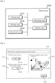
- FIG. 5 is a schematic diagram illustrating an example of the reception screen for receiving a simulation condition.
- a reception screen 210 illustrated in Fig. 5 includes a selection field 211 for selecting a battery of a simulation target, an input field 212 for inputting information related to a resistance value of a short circuit portion, and a designation field 213 for designating an occurrence location of an internal short-circuit.
- a pull-down menu 211a is arranged in the selection field 211, and a type of the battery of a simulation target is received by the pull-down menu 211a.
- An input box 212a is arranged in the input field 212, and an input of a resistance value is received as a numerical value is input using the operation unit 204, for example.
- a three-dimensional schematic diagram of the power storage device (cell) and an icon 213a indicating the occurrence location of the internal short-circuit are displayed for receiving the occurrence location of the internal short-circuit.
- a three-dimensional schematic diagram of a module, a bank, or a domain may be displayed, and a short circuit location may be received in the displayed schematic diagram.
- the reception screen 210 receives the occurrence location of the internal short-circuit by moving operation (drag operation) of the icon 213a using operation unit 204.
- an input simulation condition (information about a battery, information about a resistance value of the short circuit portion, and the occurrence location of the internal short-circuit) is transmitted from the client device 200 to the server device 100.
- the server device 100 simulates the power storage device on the basis of the simulation condition transmitted from the client device 200.
- Fig. 6 is an explanatory diagram for describing an outline of the simulation method.
- the server device 100 simulates behavior of the power storage device based on Joule heating and an exothermic reaction caused by material decomposition.
- the heat generation may include enthalpy reaction heat (reversible reaction heat) and electrochemical reaction heat (irreversible reaction heat) accompanying an electrochemical reaction.
- the server device 100 can use, for example, the Newman model for an electrochemical reaction.
- the Newman model is an electrochemical model in which homogeneous, single-diameter spheres are assumed to be arranged close to each other in the positive electrode and the negative electrode.
- the Newman model is described by the Nernst-Planck equation, a charge conservation equation, the diffusion equation, the Butler-Volmer equation, and the Nernst equation described below.
- the Nernst-Planck equation is an equation for solving ionophoresis and ion diffusion in an electrolyte or a porous electrode, and is expressed by a formula below.
- Various parameters expressed in Mathematical formulas 1 to 4 below may be configured such that a value in a bulk and a value in a porous body are appropriately converted as a function of porosity of a constituent material.
- i l is liquid phase current density (A/m 2 )
- ⁇ l eff is liquid phase conductivity (S/m)
- ⁇ l is liquid phase potential (V)
- R is a gas constant (J/(K • mol))
- T is a temperature (K)
- F is the Faraday constant (C/mol)
- f is an activity coefficient
- C l is ion concentration of the electrolyte (mol/m 3 )
- t + is a cation transport number
- i tot is reaction current density per volume (A/m 3 ).
- ⁇ s is solid phase potential (V)
- ⁇ s is solid phase conductivity (S/m)
- i s is solid phase current density (A/m 2 )
- i tot is reaction current density per volume (A/m 3 ).
- C s represents active material concentration (mol/m 3 ) in the solid phase
- t represents time (s)
- D s represents a diffusion coefficient (m 2 /s) in the solid phase.
- the Butler-Volmer equation is an equation representing an activation overvoltage in a charge transfer reaction occurring at an interface between the solid phase and the liquid phase
- i ioc reaction current density (A/m 2 )
- i 0 exchange current density (A/m 2 )
- ⁇ a and ⁇ c transition coefficients
- ⁇ an activation overvoltage (V)
- E eq equilibrium potential (V)
- E 0 standard equilibrium potential (V)
- a ox is oxidizing agent concentration (mol/m 3 )
- a red is reducing agent concentration (mol/m 3 ).
- the exchange current density i 0 may be defined as a function of, for example, ion concentration of the electrolyte solution or concentration of the active material.
- a numerical value based on an experimental result may be used instead of the theoretical formula described in Mathematical formula 4.
- actual measurement data of the state of charge (SOC) and the open circuit potential (OCP or OCV) may be used instead of the Nernst equation.
- Mathematical formula 6 is an equation describing a relationship between the flux J s of the active material and the reaction current density i loc .
- i loc zFJ s
- the Newman model is shown as an example of a model representing an electrochemical phenomenon of the power storage device.
- a single-particle model in which an electrode is represented by a single active particle, or a polynomial model in which open circuit potential and internal resistance as represented by the NTGK model are represented as a function of a temperature and a state of charge (SOC) may be used, or an equivalent circuit model may be used.
- the single-particle model is described in detail in Non-Patent Document " Cycle Life Modeling of Lithium-Ion Batteries, Gang Ning and Branko N. Popov, Journal of The Electrochemical Society, 151 (10) A 1584-A 1591 (2004 )".
- r is a reaction rate (1/s)
- k 0 is a reaction rate constant (1/s)
- E a is activation energy (J/mol)
- R is a gas constant (J/(K ⁇ mol))
- T is a temperature (K)
- x f is a reaction rate
- p, q, and Co are constants.
- Q is heat generation density (W/m 3 )
- p density (kg/m 3 )
- H p is reaction heat (J/kg).
- Joule heating is generated by the current accompanying this internal short-circuit.
- An exothermic reaction such as the material decomposition progresses according to the generation of Joule heating.
- electric resistance changes, and the magnitude of current flowing into the short circuit portion also changes.
- the Joule heating and the material decomposition exothermic reaction are not independent physical phenomena, but progress in association with each other through physical phenomena such as heat transfer.
- the server device 100 performs analysis by coupling the exothermic reaction accompanying the material decomposition and the Joule heating, and simulates a thermal phenomenon from the power storage device to the outside in consideration of, for example, a change in electric resistance due to temperature increase.
- Fig. 7 is a flowchart describing a procedure of processing executed by the server device 100 and the client device 200.
- the control unit 201 of the client device 200 receives data for the display screen transmitted from the server device 100 after the user authentication, and displays the reception screen 210 for receiving a simulation condition on the display unit 205 (Step S101).
- the control unit 201 receives a simulation condition through the reception screen 210 displayed on the display unit 205 (Step S102). Specifically, the control unit 201 receives selection of a type of a battery, information on a resistance value of the short circuit portion in the internal short-circuit, and an occurrence location of the internal short-circuit.
- the control unit 201 determines whether a transmission instruction for a simulation condition is received (Step S103). In a case where the send button 214 is operated on the reception screen 210 illustrated in Fig. 5 , the control unit 201 determines that the transmission instruction is received. In a case where the transmission instruction is received (S103: NO), the control unit 201 waits until the transmission instruction is received.
- the control unit 201 transmits the simulation condition received in Step S102 from the communication unit 203 to the server device 100 (Step S104).
- the server device 100 receives the simulation condition transmitted from the client device 200 through the communication unit 103 (Step S105).
- the control unit 101 of the server device 100 executes simulation on the basis of the condition received through the communication unit 103 (Step S106). At this time, the control unit 101 simulates a thermal phenomenon of the power storage device by executing a simulation program corresponding to behavior of the simulation target.
- the simulation condition input by the user is applied when the simulation program is executed.
- the control unit 101 couples a Joule heating reaction and an exothermic reaction of material decomposition, calculates an electromotive force, internal resistance, and the like in the power storage device by, for example, the Newman model, and calculates a reaction rate in the exothermic reaction by the Arrhenius reaction formula shown in Mathematical formula 5.
- control unit 101 can execute current calculation in consideration of a change in electric resistance due to temperature increase, and can simulate a thermal phenomenon in the power storage device while relating stop of energization due to temperature increase and a phenomenon in which a material generates heat by a decomposition reaction due to progress of the exothermic reaction. For example, it may be assumed that a portion where a material decomposition reaction progresses to a certain extent loses conductivity and energization stops.
- the control unit 101 transmits a simulation result to the client device 200 through the communication unit 103 (Step S107).
- the simulation result transmitted in Step S107 may be numerical data, or a graph, a contour diagram, a moving image, or the like generated from the numerical data.
- the simulation result transmitted in Step S107 may be a mathematical model obtained as a result of the simulation.
- the mathematical model is not merely a theoretical model, but represents a model after simulation is executed on the power storage device and various parameters are adjusted.
- the mathematical model is provided by, for example, a format of a library, a module, or the like used in commercially-available numerical analysis software or a programming language such as MATLAB (registered trademark), Amesim (registered trademark), Twin Builder (registered trademark), MATLAB & Simulink (registered trademark), Simplorer (registered trademark), ANSYS (registered trademark), Abaqus (registered trademark), Modelica (registered trademark), VHDL-AMS (registered trademark), C language, C++, or Java (registered trademark).
- MATLAB registered trademark
- Amesim registered trademark
- Twin Builder registered trademark
- MATLAB & Simulink registered trademark
- Simplorer registered trademark
- ANSYS registered trademark
- Abaqus registered trademark
- Modelica registered trademark
- VHDL-AMS registered trademark
- C language C++
- Java registered trademark
- the client device 200 receives the simulation result transmitted from the server device 100 by the communication unit 203 (Step S108).
- the control unit 201 of the client device 200 causes the display unit 205 to display the received simulation result (Step S109).
- the server device 100 can simulate a thermal phenomenon appearing in the outside from the power storage device in consideration of the exothermic reaction due to the material decomposition of the power storage device and Joule heating. Even if the user is not familiar with a physical phenomenon in the power storage device, the user can acquire a simulation result related to a thermal phenomenon of the power storage device without setting complicated simulation by inputting information related to a type of the power storage device, an occurrence location of internal short-circuit, and a resistance value of a short circuit portion from the client device 200.
- the server device 100 receives input of information related to the resistance value in the external short-circuit through the client device 200 (for example, a numerical value directly indicating a resistance value in an external short-circuit, or alternatively, information indirectly indicating a resistance value in an external short-circuit (specifically, a cause of the external short-circuit (external short-circuit between the positive electrode terminal and the negative electrode terminal by a tool such as a spanner, short-circuit outside the battery due to breakdown of insulation (coating) of wiring, short-circuit outside the battery due to crash, an external short-circuit due to a switch failure, and the like)), and simulates a thermal phenomenon based on the received information related to the resistance value of the external short-circuit.
- information related to the resistance value in the external short-circuit through the client device 200
- the client device 200 for example, a numerical value directly indicating a resistance value in an external short-circuit, or alternatively, information indirectly indicating a resistance value in an external short-circuit (specific
- control unit 101 of the server device 100 calculates current flowing from the positive electrode terminal to the negative electrode terminal of the battery by the external short-circuit. Then, the control unit 101 can simulate the power storage device and a thermal phenomenon appearing in the outside from the power storage device by performing coupled analysis of Joule heating accompanying the current and an exothermic reaction of material decomposition according to generation of Joule heating.
- a thermal phenomenon in a case where the power storage device is heated from the outside is simulated.
- the power storage device is heated due to abnormality in a surrounding environment (when a mobile body equipped with the power storage device crashes, when a cooling device in a power storage device facility fails, and the like).
- the power storage device has a rectangular parallelepiped shape (prismatic cell)
- behavior may vary depending on whether a side surface or an upper surface of the power storage device is heated.
- the power storage device is a pouch cell or a cylindrical cell.
- behaviors of the power storage device positioned inward and the power storage device positioned outward may be different from each other due to a difference in distance from a heat source and an influence of heat accumulation.
- a heating location of the power storage device by a heat source is received.
- the server device 100 receives, through the client device 200, simulation conditions including a heating location, an amount of heat, and an environmental temperature when the power storage device is heated from the outside.
- the heating location may be received via a user interface including graphical display similar to that of Fig. 5 .
- the server device 100 simulates a thermal phenomenon based on the received simulation condition.
- the control unit 101 of the server device 100 analyzes a material decomposition reaction that progresses according to heat applied from the outside using the Arrhenius reaction formula, so as to simulate a thermal phenomenon appearing in the outside from the power storage device.
- Fig. 8 is an explanatory view for describing a constituent element of a power storage device 1 according to the third embodiment.
- the power storage device 1 according to the third embodiment includes a wound electrode assembly 10v, a positive electrode terminal 11, a positive electrode current collector 11a, a negative electrode terminal 12, and a negative electrode current collector 12a, and for example, they are housed in a hollow rectangular parallelepiped case 20.
- a separator made from a porous resin film is disposed between a strip-shaped negative electrode in which a negative active material is provided on negative electrode current collecting foil made from copper foil and a strip-shaped positive electrode in which a positive active material is provided on positive electrode current collecting foil made from aluminum foil disposed in a manner shifted in the width direction of the negative electrode, and these are wound to constitute the wound electrode assembly 10v.
- the positive electrode current collector 11a electrically connects the positive electrode terminal 11 and a positive electrode (active material non-forming portion, positive electrode current collecting foil) of the electrode assembly 10v.
- the negative electrode current collector 12a electrically connects the negative electrode terminal 12 and a negative electrode (active material non-forming portion, negative electrode current collecting foil) of the electrode assembly 10v.
- the positive electrode current collector 11a is electrically connected to the positive electrode of the electrode assembly 10v at at least one point
- the negative electrode current collector 12a is electrically connected to the negative electrode of the electrode assembly 10v at at least one point. Positions of the positive electrode current collector 11a and the negative electrode current collector 12a may be in various forms within a range in which the electrical connection with the positive electrode and the negative electrode of the electrode assembly 10v does not change.
- the direction of the winding center of the electrode assembly 10v is directed in the X axis direction in the drawing.
- the direction of the winding center of the electrode assembly 10v may be the Y axis direction or the Z axis direction in the drawing.
- Fig. 9 is a diagram illustrating an electrode assembly of a type having an electrode tab in a wound cell.
- a plurality of negative electrode tabs 12b active material non-forming portions
- a plurality of positive electrode tabs 11b active material non-forming portions
- a separator is disposed between the negative electrode and the positive electrode, and these are wound to constitute a wound electrode assembly.
- a plurality of the negative electrode tabs 12b and a plurality of the positive electrode tabs 11b are bundled and electrically connected to a negative electrode current collector and a positive electrode current collector (not illustrated), respectively.
- a short circuit occurs from an electrode other than a short-circuit layer through only a tab at the time of a short circuit.
- a wound cell there are two types of current: current flowing from a short-circuit layer through the tab (the positive electrode tab 11b or the negative electrode tab 12b); and a current flowing from a curved portion between the wound cell and an adjacent electrode. For this reason, in the wound cell, a calculation method used in a laminated cell cannot be used.
- short-circuit current is calculated in a state where the wound electrode assembly is virtually developed and expanded.
- Typical examples performed in the simulation of the internal short-circuit include a through short circuit represented by a nail penetration test and a partial short-circuit represented by a nickel piece mixing test. Hereinafter, each will be described in detail.
- Fig. 10 is an explanatory view for describing an appearance location of a short circuit portion in a through short circuit in the wound electrode assembly shown in Fig. 9 .
- shapes and sizes of the wound electrode assembly 10 are deformed.
- the example of Fig. 10 shows a state in which a conductor such as a nail penetrates the wound electrode assembly in a wound cell of three turns, that is, six layers in total.
- the developed model is a three-dimensional model in which positive electrode current collecting foil, a positive active material, a separator, a negative active material, and negative electrode current collecting foil are arranged from the near side to the far side of the drawing.
- the positive electrode tab 11b exists in the same plane (at the same position in the depth direction) as the positive electrode current collecting foil, and is electrically connected to the strip-shaped positive electrode current collecting foil of the developed electrode assembly 10 in six locations.
- the negative electrode tab 12b exists in the same plane (at the same position in the depth direction) as the negative electrode current collecting foil, and is electrically connected to the strip-shaped negative electrode current collecting foil of the developed electrode assembly 10 in six locations.
- the positive electrode tab 11b and the negative electrode tab 12b are not directly electrically connected.
- a portion connecting a plurality of the positive electrode tabs 11b (a plurality of the negative electrode tabs 12b) in the lateral direction in the drawing is a virtual conductive path representing electrical connection of a plurality of tabs by tab binding as shown in Fig. 9 .
- Fig. 10 in the case of the through short circuit, when the wound electrode assembly is developed, a plurality of short circuit portions appear in the longitudinal direction of the cell.
- a short-circuit phenomenon occurring inside the wound cell can be appropriately expressed, and a thermal phenomenon appearing in the outside from the wound cell can be accurately simulated.
- the wound electrode assembly has a portion where an electrode is bent, which is referred to as a curved portion 10a shown in Fig. 10 .
- a physical property value for example, electric conductivity, porosity, liquid phase conductivity, and the like
- An appropriate physical property value for example, electron conductivity of 1.0 ⁇ 10 10 S/m or the like
- the short circuit position is not limited to the center of the wound electrode assembly, and calculation can be performed by the same modeling method even when the short circuit position is in the vicinity of the tab or the vicinity of the curved portion 10a, for example.
- Fig. 11 is an explanatory view for describing an appearance location of a short circuit portion in a partial short circuit in the wound electrode assembly.
- shapes and sizes of the wound electrode assembly 10 are deformed.
- the example of Fig. 11 shows a state in which a conductor such as a nickel piece short-circuits a part of the wound electrode assembly.
- the developed model is a three-dimensional model in which positive electrode current collecting foil, a positive active material, a separator, a negative active material, and negative electrode current collecting foil are arranged from the near side to the far side of the drawing.
- the wound electrode assembly when the wound electrode assembly is developed, one short circuit portion appears in the longitudinal direction of the cell.
- the wound electrode assembly has a portion where an electrode is bent, which is referred to as the curved portion 10a shown in Fig. 11 .
- a physical property value for example, electric conductivity, porosity, liquid phase conductivity, and the like
- An appropriate physical property value for example, electron conductivity of 1.0 ⁇ 10 10 S/m or the like
- the short circuit position is not limited to the center of the wound electrode assembly, and does not need to be the outermost peripheral layer.
- the simulation of short-circuit current in the shape in which the wound electrode assembly is developed and the simulation of the heat transfer and the exothermic reaction performed in the actual shape are performed in a coupled manner, so that calculation more accurately expressing the actual object can be performed.
- a heat generation rate in the material decomposition reaction of the power storage device is calculated.
- the server device 100 uses the above-described Arrhenius reaction formula of Mathematical formula 5 known as a Dahn model as a formula describing the exothermic reaction of the material decomposition reaction.
- the control unit 101 of the server device 100 calculates a reaction rate x f using the Arrhenius reaction formula of Mathematical formula 5.
- reaction rate x f and heat generation density Q are calculated using the Arrhenius reaction formula of Mathematical formula 5
- values of a reaction rate constant k 0 , activation energy E a , and constants p, q, and C 0 are required.
- a graph of a relationship of temperature-calorific value obtained by the differential thermal analysis is converted into a relationship of time-calorific value, and then fitting is performed to acquire each of the parameters described above.
- the present embodiment discloses a method of acquiring each parameter using the graph of the relationship of temperature-calorific value obtained by the differential thermal analysis without conversion.
- control unit 101 fits the data of temperature-calorific value obtained by the differential thermal analysis using a Lorentz function, a Gaussian function, or the like to acquire a relational expression of temperature-calorific value.
- the fitting by the Lorentz function or the Gaussian function is performed using an appropriate optimization tool.
- control unit 101 converts heat generation density Q(T) obtained as a function of temperature into heat generation density Q(t) represented as a function of time by using an equation of differential chain rule shown in a formula below.
- a factor represented by time partial differentiation of a temperature T is calculated in the course of calculation.
- a safety mechanism such as a rupture valve that is operated by pressure, and when internal pressure is increased by gas generation inside the housing, the rupture valve is opened, and the gas is ejected to the outside.
- this gas Since this gas has a high temperature, this gas causes a spreading fire to an adjacent cell and burning of a structural member. Further, since harmful gas such as carbon monoxide may be contained in the gas ejected from the power storage device, predicting an ambient temperature in consideration of a temperature, a flow rate, and gas concentration is important in the safety design of the power storage device and an entire product including the power storage device.
- the server device 100 simulates gas generation based on the exothermic reaction due to the material decomposition reaction.
- the calculated amounts can be used for thermal design and safety design of an electric vehicle, a power plant, and the like.
- reaction involved in gas generation for example, gas generation by oxygen extracted from a positive active material and an electrolyte solution and gas generation by thermal decomposition of an organic auxiliary agent contained in an electrode are known. These reactions are numbered 1, 2, ..., i, ... for convenience. Practically, it is difficult to analyze and consider in detail an elementary reaction process related to gas generation of a battery. In view of the above, a method of collating a differential thermal analysis (DSC) chart, a result of gas amount measurement, and the like to separate the reaction may be employed.
- DSC differential thermal analysis
- v i normal volume of the gas generated in a case where the reaction i completely progresses
- x fi is a reaction rate of the reaction i.
- the control unit 101 calculates pressure inside the power storage device housing.
- the gas in the housing is assumed to be ideal gas.
- P 0 is initial internal pressure (Pa) of the power storage device housing, and is usually 1 (atm).
- V gap is volume (m 3 ) of a gas existing region in the power storage device housing
- T is a gas temperature (K)
- T 0 is a reference temperature (K).
- the rupture valve of the power storage device is configured to open when a condition of P th ⁇ P in is satisfied.
- P th is a threshold of internal pressure at which the rupture valve is opened. After the rupture valve is opened, gas generated by the reaction is discharged to the outside from the opened rupture valve.
- q norm, tot represents a generation volume rate (m 3 /s) of the normal gas
- v i volume (m 3 ) of the normal gas generated by the i-th reaction
- r i represents a reaction rate (1/s) of the i-th reaction
- v vent is an ejected gas velocity (m/s) of the gas ejected from the opening portion of the rupture valve. This value may be used as a velocity boundary condition for gas ejection from the opening portion of the rupture valve as it is, or a parabolic velocity distribution may be provided.
- a value in consideration of convergence may be provided to a term specific to the turbulence model such as turbulence energy or a turbulence disappearance rate.
- the control unit 101 calculates a heat generation rate due to the exothermic reaction as well as a gas ejection velocity.
- the method for calculating the heat generation rate may be the same as the method described in the first embodiment.
- An amount of heat generated by the exothermic reaction is appropriately distributed to the ejection gas and the power storage device.
- a distribution ratio at this time a method of distributing the amount of heat by a ratio of each heat capacity by assuming that the gas and the power storage device instantaneously reach thermal equilibrium may be employed.
- a distribution ratio of the amounts of heat to the ejection gas and the power storage device may be provided so as to match an experimental result.
- a single power storage device is described as an example.
- simulation can also be executed for a system (assembled battery or the like) including a plurality of power storage devices.
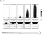
- Fig. 12 is a schematic view illustrating a system (assembled battery) including a plurality of power storage devices
- Fig. 13 is graphic display (moving image display) visualizing a state in which a plurality of power storage devices discharge gas in a chain manner in the system of Fig. 12 .
- simulation methods may be implemented as a simulation device or a computer program.
- the simulation target is described focusing on a thermal influence of the power storage device on the outside.
- attention may be paid to the inside of the power storage device.
- gas ejected from the power storage device has an effect of suppressing temperature increase of the power storage device. For this reason, it is also possible to calculate a state inside the power storage device with exactly the same idea.
- the simulation method of the present application can be utilized to determine whether or not the rupture valve is opened by gas generation and increase in internal pressure due to material decomposition.
- the simulation method of the present application can also be utilized to examine whether or not a spreading fire to a peripheral power storage device occurs if the rupture valve is opened and gas is ejected.
- an effect of a heat insulating material, a refractory material, and the like for preventing a spreading fire can be checked by calculation, which is a means for strongly promoting product design based on the idea of model-based development.
- the embodiment may be such that a server administrator provides a simulation program to the client user by means of a storage medium such as a DVD-ROM, and the simulation is performed locally in a client terminal.
- a providing means may be a download form via communication.
Landscapes
- Engineering & Computer Science (AREA)
- Computer Hardware Design (AREA)
- Physics & Mathematics (AREA)
- Theoretical Computer Science (AREA)
- Chemical Kinetics & Catalysis (AREA)
- General Chemical & Material Sciences (AREA)
- Electrochemistry (AREA)
- Chemical & Material Sciences (AREA)
- Evolutionary Computation (AREA)
- Geometry (AREA)
- General Engineering & Computer Science (AREA)
- General Physics & Mathematics (AREA)
- Manufacturing & Machinery (AREA)
- Microelectronics & Electronic Packaging (AREA)
- Secondary Cells (AREA)
Applications Claiming Priority (3)
| Application Number | Priority Date | Filing Date | Title |
|---|---|---|---|
| JP2019051226 | 2019-03-19 | ||
| JP2019232048A JP6699795B1 (ja) | 2019-03-19 | 2019-12-23 | シミュレーション方法、シミュレーション装置、及びコンピュータプログラム |
| PCT/JP2020/003127 WO2020189034A1 (fr) | 2019-03-19 | 2020-01-29 | Procédé de simulation, dispositif de simulation et programme informatique |
Publications (2)
| Publication Number | Publication Date |
|---|---|
| EP3944400A1 true EP3944400A1 (fr) | 2022-01-26 |
| EP3944400A4 EP3944400A4 (fr) | 2022-05-04 |
Family
ID=70776046
Family Applications (1)
| Application Number | Title | Priority Date | Filing Date |
|---|---|---|---|
| EP20772540.9A Pending EP3944400A4 (fr) | 2019-03-19 | 2020-01-29 | Procédé de simulation, dispositif de simulation et programme informatique |
Country Status (5)
| Country | Link |
|---|---|
| US (1) | US20220188478A1 (fr) |
| EP (1) | EP3944400A4 (fr) |
| JP (1) | JP6699795B1 (fr) |
| CN (1) | CN113597699A (fr) |
| WO (1) | WO2020189034A1 (fr) |
Families Citing this family (8)
| Publication number | Priority date | Publication date | Assignee | Title |
|---|---|---|---|---|
| JP7521335B2 (ja) * | 2020-08-31 | 2024-07-24 | 株式会社Gsユアサ | 検出装置、検出方法及びコンピュータプログラム |
| CN114323532B (zh) * | 2021-12-31 | 2026-02-03 | 蔚来汽车科技(安徽)有限公司 | 用于动力电池的碰撞试验方法和碰撞试验系统 |
| CN115034093B (zh) * | 2022-08-10 | 2022-11-15 | 中国汽车技术研究中心有限公司 | 带热网络的电机仿真模型构建方法和仿真方法 |
| CN115935766B (zh) * | 2022-11-04 | 2026-03-24 | 中国空间技术研究院 | 一种功率vdmos器件总剂量和单粒子栅击穿协和效应仿真方法 |
| CN118731816B (zh) * | 2024-08-06 | 2025-05-27 | 青岛艾诺仪器有限公司 | 一种电池微短路的模拟系统 |
| WO2026071046A1 (fr) * | 2024-09-27 | 2026-04-02 | パナソニックIpマネジメント株式会社 | Procédé de traitement d'informations, programme, support de stockage, dispositif de traitement d'informations et structure de données |
| WO2026071047A1 (fr) * | 2024-09-27 | 2026-04-02 | パナソニックIpマネジメント株式会社 | Procédé de simulation, programme, support de stockage, dispositif de simulation et structure de données |
| WO2026071048A1 (fr) * | 2024-09-27 | 2026-04-02 | パナソニックIpマネジメント株式会社 | Procédé de simulation, programme, support de stockage, dispositif de simulation et structure de données |
Family Cites Families (9)
| Publication number | Priority date | Publication date | Assignee | Title |
|---|---|---|---|---|
| JPH1114507A (ja) | 1997-06-19 | 1999-01-22 | Denso Corp | 車両シミュレーション装置 |
| JP4576903B2 (ja) * | 2004-06-29 | 2010-11-10 | 三菱化学株式会社 | 温度分布評価方法並びにシミュレーション装置及びシミュレーションプログラム |
| JP2012069496A (ja) * | 2010-09-27 | 2012-04-05 | Denso Corp | 電池加熱装置 |
| US9678163B2 (en) * | 2011-01-18 | 2017-06-13 | Tiax Llc | Differential current monitoring for parallel-connected batteries |
| JP6001823B2 (ja) * | 2011-01-24 | 2016-10-05 | 株式会社豊田中央研究所 | 二次電池のシミュレーション装置 |
| JP2013101884A (ja) * | 2011-11-09 | 2013-05-23 | Toyota Motor Corp | 二次電池の温度推定方法および二次電池の制御方法 |
| JP2016090399A (ja) * | 2014-11-05 | 2016-05-23 | 日本電信電話株式会社 | 短絡検出方法、短絡検出システムおよび短絡電流値算出方法 |
| JP2017059343A (ja) * | 2015-09-15 | 2017-03-23 | 三菱製紙株式会社 | リチウムイオン二次電池用部材の評価方法 |
| KR102589287B1 (ko) * | 2017-01-19 | 2023-10-13 | 내션얼 리서치 카운슬 오브 캐나다 | 배터리에서 열폭주를 개시하기 위한 장치 및 방법 |
-
2019
- 2019-12-23 JP JP2019232048A patent/JP6699795B1/ja active Active
-
2020
- 2020-01-29 WO PCT/JP2020/003127 patent/WO2020189034A1/fr not_active Ceased
- 2020-01-29 EP EP20772540.9A patent/EP3944400A4/fr active Pending
- 2020-01-29 CN CN202080018444.1A patent/CN113597699A/zh active Pending
- 2020-01-29 US US17/440,113 patent/US20220188478A1/en active Pending
Also Published As
| Publication number | Publication date |
|---|---|
| US20220188478A1 (en) | 2022-06-16 |
| CN113597699A (zh) | 2021-11-02 |
| JP2020161115A (ja) | 2020-10-01 |
| EP3944400A4 (fr) | 2022-05-04 |
| JP6699795B1 (ja) | 2020-05-27 |
| WO2020189034A1 (fr) | 2020-09-24 |
Similar Documents
| Publication | Publication Date | Title |
|---|---|---|
| EP3944400A1 (fr) | Procédé de simulation, dispositif de simulation et programme informatique | |
| Wang et al. | Advances and challenges in thermal runaway modeling of lithium-ion batteries | |
| Liu et al. | Integrated computation model of lithium-ion battery subject to nail penetration | |
| Chen et al. | Electro-thermal coupling model of lithium-ion batteries under external short circuit | |
| Sun et al. | Thermal runaway characteristics and modeling of LiFePO4 power battery for electric vehicles | |
| Doughty et al. | Lithium battery thermal models | |
| Madani et al. | Thermal characteristics and safety aspects of lithium-ion batteries: An in-depth review | |
| Li et al. | Parametric study on the safety behavior of mechanically induced short circuit for lithium-ion pouch batteries | |
| US12271664B2 (en) | Simulation method of a battery using molten salt as an electrolyte, and associated simulation device | |
| JP7480541B2 (ja) | 開発支援装置、及び開発支援方法 | |
| Jia et al. | Dynamics of Intra‐Cell Thermal Front Propagation in Lithium‐Ion Battery Safety Issues | |
| Hoelle et al. | 3d thermal simulation of lithium-ion battery thermal runaway in autoclave calorimetry: Development and comparison of modeling approaches | |
| Brik et al. | Causal and fault trees analysis of proton exchange membrane fuel cell degradation | |
| Roberts et al. | TABS: A Thermal Battery Desktop Design Tool. | |
| Xu et al. | A multiphysics simulation of the thermal runaway in large-format lithium-ion batteries | |
| Wang et al. | Unveiling the explosion potential of lithium-ion batteries: a quantitative approach to safety assessment | |
| Long et al. | Experimental and modeling approaches for electric vehicle battery safety: a technical review | |
| EP3951995A1 (fr) | Dispositif d'aide au développement, procédé d'aide au développement et programme informatique | |
| Huang et al. | Modelling thermal runaway initiation and propagation for batteries in dwellings to evaluate tenability conditions | |
| Wurzenberger et al. | Battery thermal management simulation-1d+ 1D electrochemical battery and 3D module modeling on vehicle system level | |
| Li et al. | Safety optimal design of lithium-ion battery cell based on multiphysics models | |
| Wang et al. | An investigation of critical parameters on spontaneous combustion for lithium-ion battery using bifurcation theory | |
| Qatramez | The Role of Lithium-Ion Batteries Vent Gas Production on Thermal Runaway Propagation in Containerized Energy Storage Systems | |
| Khan | Thermal management of battery systems in electric vehicle and smart grid application | |
| Masias | Ford Safety Performance of Rechargeable Energy Storage Systems (RESS) |
Legal Events
| Date | Code | Title | Description |
|---|---|---|---|
| STAA | Information on the status of an ep patent application or granted ep patent |
Free format text: STATUS: THE INTERNATIONAL PUBLICATION HAS BEEN MADE |
|
| PUAI | Public reference made under article 153(3) epc to a published international application that has entered the european phase |
Free format text: ORIGINAL CODE: 0009012 |
|
| STAA | Information on the status of an ep patent application or granted ep patent |
Free format text: STATUS: REQUEST FOR EXAMINATION WAS MADE |
|
| 17P | Request for examination filed |
Effective date: 20211014 |
|
| AK | Designated contracting states |
Kind code of ref document: A1 Designated state(s): AL AT BE BG CH CY CZ DE DK EE ES FI FR GB GR HR HU IE IS IT LI LT LU LV MC MK MT NL NO PL PT RO RS SE SI SK SM TR |
|
| A4 | Supplementary search report drawn up and despatched |
Effective date: 20220407 |
|
| RIC1 | Information provided on ipc code assigned before grant |
Ipc: H01M 10/42 20060101ALI20220401BHEP Ipc: G06F 30/10 20200101ALI20220401BHEP Ipc: G06F 30/20 20200101ALI20220401BHEP Ipc: H01M 10/48 20060101AFI20220401BHEP |
|
| DAV | Request for validation of the european patent (deleted) | ||
| DAX | Request for extension of the european patent (deleted) |