EP3944599A1 - Structure de support et dispositif d'affichage pliable - Google Patents
Structure de support et dispositif d'affichage pliable Download PDFInfo
- Publication number
- EP3944599A1 EP3944599A1 EP20798686.0A EP20798686A EP3944599A1 EP 3944599 A1 EP3944599 A1 EP 3944599A1 EP 20798686 A EP20798686 A EP 20798686A EP 3944599 A1 EP3944599 A1 EP 3944599A1
- Authority
- EP
- European Patent Office
- Prior art keywords
- bending
- supporting
- flexible screen
- flexible
- display apparatus
- Prior art date
- Legal status (The legal status is an assumption and is not a legal conclusion. Google has not performed a legal analysis and makes no representation as to the accuracy of the status listed.)
- Granted
Links
Images




Classifications
-
- H—ELECTRICITY
- H04—ELECTRIC COMMUNICATION TECHNIQUE
- H04M—TELEPHONIC COMMUNICATION
- H04M1/00—Substation equipment, e.g. for use by subscribers
- H04M1/02—Constructional features of telephone sets
- H04M1/0202—Portable telephone sets, e.g. cordless phones, mobile phones or bar type handsets
- H04M1/026—Details of the structure or mounting of specific components
- H04M1/0266—Details of the structure or mounting of specific components for a display module assembly
-
- G—PHYSICS
- G09—EDUCATION; CRYPTOGRAPHY; DISPLAY; ADVERTISING; SEALS
- G09F—DISPLAYING; ADVERTISING; SIGNS; LABELS OR NAME-PLATES; SEALS
- G09F9/00—Indicating arrangements for variable information in which the information is built-up on a support by selection or combination of individual elements
- G09F9/30—Indicating arrangements for variable information in which the information is built-up on a support by selection or combination of individual elements in which the desired character or characters are formed by combining individual elements
- G09F9/301—Indicating arrangements for variable information in which the information is built-up on a support by selection or combination of individual elements in which the desired character or characters are formed by combining individual elements flexible foldable or roll-able electronic displays, e.g. thin LCD, OLED
-
- G—PHYSICS
- G06—COMPUTING OR CALCULATING; COUNTING
- G06F—ELECTRIC DIGITAL DATA PROCESSING
- G06F1/00—Details not covered by groups G06F3/00 - G06F13/00 and G06F21/00
- G06F1/16—Constructional details or arrangements
- G06F1/1613—Constructional details or arrangements for portable computers
- G06F1/1633—Constructional details or arrangements of portable computers not specific to the type of enclosures covered by groups G06F1/1615 - G06F1/1626
- G06F1/1637—Details related to the display arrangement, including those related to the mounting of the display in the housing
-
- G—PHYSICS
- G06—COMPUTING OR CALCULATING; COUNTING
- G06F—ELECTRIC DIGITAL DATA PROCESSING
- G06F1/00—Details not covered by groups G06F3/00 - G06F13/00 and G06F21/00
- G06F1/16—Constructional details or arrangements
- G06F1/1613—Constructional details or arrangements for portable computers
- G06F1/1633—Constructional details or arrangements of portable computers not specific to the type of enclosures covered by groups G06F1/1615 - G06F1/1626
- G06F1/1637—Details related to the display arrangement, including those related to the mounting of the display in the housing
- G06F1/1641—Details related to the display arrangement, including those related to the mounting of the display in the housing the display being formed by a plurality of foldable display components
-
- G—PHYSICS
- G06—COMPUTING OR CALCULATING; COUNTING
- G06F—ELECTRIC DIGITAL DATA PROCESSING
- G06F1/00—Details not covered by groups G06F3/00 - G06F13/00 and G06F21/00
- G06F1/16—Constructional details or arrangements
- G06F1/1613—Constructional details or arrangements for portable computers
- G06F1/1633—Constructional details or arrangements of portable computers not specific to the type of enclosures covered by groups G06F1/1615 - G06F1/1626
- G06F1/1637—Details related to the display arrangement, including those related to the mounting of the display in the housing
- G06F1/1652—Details related to the display arrangement, including those related to the mounting of the display in the housing the display being flexible, e.g. mimicking a sheet of paper, or rollable
-
- H—ELECTRICITY
- H04—ELECTRIC COMMUNICATION TECHNIQUE
- H04M—TELEPHONIC COMMUNICATION
- H04M1/00—Substation equipment, e.g. for use by subscribers
- H04M1/02—Constructional features of telephone sets
- H04M1/0202—Portable telephone sets, e.g. cordless phones, mobile phones or bar type handsets
- H04M1/0206—Portable telephones comprising a plurality of mechanically joined movable body parts, e.g. hinged housings
- H04M1/0208—Portable telephones comprising a plurality of mechanically joined movable body parts, e.g. hinged housings characterized by the relative motions of the body parts
- H04M1/0214—Foldable telephones, i.e. with body parts pivoting to an open position around an axis parallel to the plane they define in closed position
-
- H—ELECTRICITY
- H04—ELECTRIC COMMUNICATION TECHNIQUE
- H04M—TELEPHONIC COMMUNICATION
- H04M1/00—Substation equipment, e.g. for use by subscribers
- H04M1/02—Constructional features of telephone sets
- H04M1/0202—Portable telephone sets, e.g. cordless phones, mobile phones or bar type handsets
- H04M1/0206—Portable telephones comprising a plurality of mechanically joined movable body parts, e.g. hinged housings
- H04M1/0208—Portable telephones comprising a plurality of mechanically joined movable body parts, e.g. hinged housings characterized by the relative motions of the body parts
- H04M1/0214—Foldable telephones, i.e. with body parts pivoting to an open position around an axis parallel to the plane they define in closed position
- H04M1/0216—Foldable in one direction, i.e. using a one degree of freedom hinge
-
- H—ELECTRICITY
- H04—ELECTRIC COMMUNICATION TECHNIQUE
- H04M—TELEPHONIC COMMUNICATION
- H04M1/00—Substation equipment, e.g. for use by subscribers
- H04M1/02—Constructional features of telephone sets
- H04M1/0202—Portable telephone sets, e.g. cordless phones, mobile phones or bar type handsets
- H04M1/026—Details of the structure or mounting of specific components
- H04M1/0266—Details of the structure or mounting of specific components for a display module assembly
- H04M1/0268—Details of the structure or mounting of specific components for a display module assembly including a flexible display panel
-
- H—ELECTRICITY
- H05—ELECTRIC TECHNIQUES NOT OTHERWISE PROVIDED FOR
- H05K—PRINTED CIRCUITS; CASINGS OR CONSTRUCTIONAL DETAILS OF ELECTRIC APPARATUS; MANUFACTURE OF ASSEMBLAGES OF ELECTRICAL COMPONENTS
- H05K5/00—Casings, cabinets or drawers for electric apparatus
- H05K5/02—Details
- H05K5/0217—Mechanical details of casings
Definitions
- This application relates to the field of foldable display apparatus technologies, and in particular, to a supporting structure and a foldable display apparatus.
- a foldable mobile phone with a flexible screen is an important development trend of modern mobile phones.
- the flexible screen usually includes planar regions and a bending region connecting two adjacent planar regions.
- a supporting structure of the foldable mobile phone with a flexible screen includes planar supporting portions opposite to the planar regions and a bending supporting portion opposite to the bending region.
- the flexible screen is bonded and fastened to the supporting structure.
- the bending supporting portion includes an intermediate skeleton and a flexible supporting bar injection-molded with the intermediate skeleton, and the flexible screen is bonded and fastened to the flexible supporting bar.
- the bending supporting portion and the bending region of the flexible screen are simultaneously bent or unfolded, and the bending supporting portion and the flexible screen each have a specified thickness.
- the flexible screen needs to stretch and contract. Consequently, degumming is likely caused between the flexible screen and the bending supporting portion, resulting in poor products.
- This application provides a supporting structure of a foldable display apparatus and a foldable display apparatus, to improve strength of connection between a flexible screen and a bending supporting portion, and improve product quality of the foldable display apparatus.
- this application provides a supporting structure of a foldable display apparatus, where the supporting structure of the foldable display apparatus is configured to support a flexible screen of the foldable display apparatus.
- the flexible screen includes two types of regions: planar regions and a bending region.
- the flexible screen includes at least two planar regions and a bending region connected between the two planar regions.
- the supporting structure of the foldable display apparatus includes two types of parts: planar supporting portions and a bending supporting portion.
- the planar supporting portions are opposite to the planar regions and support the planar regions of the flexible screen, and the bending supporting portion is opposite to the bending region and supports the bending region of the flexible screen.
- the bending supporting portion includes two parts: a bending skeleton and a flexible supporting bar connected to the bending skeleton, and the flexible supporting bar is in direct contact with the flexible screen.
- the flexible supporting bar When the flexible screen is unfolded, the flexible supporting bar is configured to support the bending region of the flexible screen, and when the flexible screen is folded, the flexible supporting bar is configured to drive the flexible screen to be folded.
- the flexible supporting bar includes at least two parts: a supporting portion and a plurality of connecting portions that are distributed at intervals and fastened to the supporting portion.
- the supporting portion is connected to the flexible screen.
- the plurality of connecting portions are located on a side of the supporting portion away from the flexible screen, and the plurality of connecting portions are distributed at intervals.
- the flexible screen is bonded and fastened to the supporting portion of the flexible supporting bar.
- the supporting portion and the flexible screen are bent together, and the supporting portion is connected to the bending skeleton by using the plurality of connecting portions distributed at intervals. Therefore, during bending, relative displacement is generated between the supporting portion and the bending skeleton, so that no relative displacement is likely generated between the supporting portion and the flexible screen. This improves strength of connection between the supporting portion and the flexible screen, reduces a risk of degumming between the flexible screen and the flexible supporting bar, and improves product quality of the foldable display apparatus.
- the connecting portions may be clamping slot structures
- the bending skeleton includes clamping heads clamped with the clamping slot structures.
- the clamping head extends into the clamping slot structure for clamping, to implement connection between the flexible supporting bar and the bending skeleton.
- the supporting portion and the flexible screen are bent together, and displacement is generated between the clamping slot of the supporting portion and the bending skeleton, so that no relative displacement is likely generated between the supporting portion and the flexible screen. This improves strength of connection between the supporting portion and the flexible screen, reduces a risk of degumming between the flexible screen and the flexible supporting bar, and improves product quality of the foldable display apparatus.
- the connecting portions may be fixed protrusions
- the plurality of fixed protrusions are located on a side of the supporting portion away from the flexible screen, and an end of each of the plurality of fixed protrusions away from the supporting portion is connected to the bending skeleton. Therefore, there is a specified distance from the joint between the flexible supporting bar and the bending skeleton to the supporting portion.
- the flexible screen is bonded and fastened to the supporting portion of the flexible supporting bar.
- the supporting portion and the flexible screen are bent together, and displacement is generated between the fixed protrusion of the supporting portion and the bending skeleton, so that no relative displacement is likely generated between the supporting portion and the flexible screen. This improves strength of connection between the supporting portion and the flexible screen.
- the fixed protrusion of the flexible supporting bar is connected to the bending skeleton.
- the fixed protrusion of the flexible supporting bar is clamped with the bending skeleton.
- the fixed protrusions have fasteners
- the bending skeleton includes bayonets in one-to-one adaptation with the fasteners of the fixed protrusions
- the fastener may be clamped with the bayonet
- the fastener of the fixed protrusion extends into the bayonet and is clamped with the bayonet.
- the flexible supporting bar is flexible.
- the fastener may contract and deform to pass through the bayonet, and spring back after passing through the bayonet, to be clamped with the bayonet.
- a small amount of displacement may be alternatively generated between the fastener and the bayonet, but an effect of connection between the fastener and the bayonet may not be affected. Therefore, relative displacement generated between layers in a folding region when the foldable display apparatus is folded may be further absorbed. In this way, this can improve strength of connection between the supporting portion and the flexible screen, and reduce a disk of degumming between the flexible screen and the flexible supporting bar.
- a manner for connection between the fastener and the bayonet further includes different implementation solutions.
- the bayonet may be a groove, or may be a through hole.
- an opening of the groove has a clamping edge.
- a size of the opening of the groove is less than a size of a bottom region of the groove.
- the bayonet When the bayonet is a through hole, after the fastener of the fixed protrusion contracts to pass through the through hole, the fastener springs back and is clamped with an edge of the through hole, to complete clamping between the flexible supporting bar and the bending skeleton.
- a structure of the through hole is relatively simple, and therefore a manufacturing process can be simplified.
- the bending skeleton includes mounting portions in one-to-one adaptation with the fixed protrusions, and the fixed protrusion is fastened to the mounting portion, to complete mounting and connection between the flexible supporting bar and the bending skeleton.
- the mounting portion has a mounting hole.
- the fixed protrusion passes through the mounting hole of the mounting portion and is then fastened to the mounting portion. Therefore, a hole wall of the mounting hole can limit the fixed protrusion to some extent. In this way, a region in which the fixed protrusion is fixedly connected to the mounting portion does not likely fall off.
- a manner for fixed connection between the fixed protrusion and the bending skeleton further includes different implementation solutions.
- the fixed protrusion may be bonded and fastened to the mounting portion.
- a process in this solution is relatively simple.
- the fixed protrusion may be hot-melt in the mounting portion. In this solution, connection is relatively stable, and falling-off does not likely occur.
- a shape of the foregoing connecting portion is not specifically limited.
- the connecting portions may be bar-shaped connecting portions or dot-shaped connecting portions.
- the shape of the connecting portion may be selected based on an actual product requirement.
- the connecting portions are bar-shaped connecting portions
- the bar-shaped connecting portions extend in an extension direction of the flexible supporting bar
- the plurality of bar-shaped connecting portions are disposed in parallel.
- a folding direction is perpendicular to the extension direction of the flexible supporting bar. Therefore, in this technical solution, the bar-shaped connecting portions do not need to be bent drastically, and a region between the bar-shaped connecting portions in parallel may be bent drastically, to facilitate a bending operation.
- the bar-shaped connecting portions are not likely damaged. This improves a service life.
- the connecting portions are dot-shaped connecting portions
- the dot-shaped connecting portions are arranged in a matrix on the supporting portion.
- a relatively reliable connection relationship can be provided.
- the flexible screen may have one bending region, or may have two or more bending regions.
- the supporting structure of the foldable display apparatus in this application may include one bending supporting portion, or may include two bending supporting portions.
- the technical solution of this application can be used provided that the foldable display apparatus includes the bending supporting portion, to improve strength of connection between the flexible screen and the bending supporting portion, and improve product quality of the foldable display apparatus.
- this application further provides a foldable display apparatus, where the foldable display apparatus includes a flexible screen and the supporting structure of the foldable display apparatus in any one of the foregoing technical solutions.
- a bending supporting portion of the supporting structure includes a flexible supporting bar and a bending skeleton. Distal ends of connecting portions of the flexible supporting bar are fixedly connected to the bending skeleton. Therefore, there may be space for relative movement between the flexible supporting bar and the bending skeleton.
- the flexible screen may be stably connected to a supporting portion of the supporting bar, and degumming does not likely occur, so that product quality of the foldable display apparatus is relatively high.
- a folding direction of the foregoing foldable display apparatus is not limited.
- the foldable display apparatus may be folded in a direction towards the flexible screen.
- the flexible screen is located between supporting housings of the foldable display apparatus.
- the foldable display apparatus may be folded in a direction away from the flexible screen.
- the flexible screen is located on outer sides of supporting housings of the foldable display apparatus.
- the supporting structure of the foldable display apparatus is applied to a foldable mobile terminal, for example, a foldable mobile phone or a foldable ebook.
- a foldable mobile terminal for example, a foldable mobile phone or a foldable ebook.
- a flexible screen of the mobile terminal is also folded.
- the flexible screen includes two types of regions: planar regions and a bending region connecting two adjacent planar regions.
- the supporting structure of the foldable display apparatus includes planar supporting portions and a bending supporting portion. The planar supporting portions are opposite to the planar regions, and the bending supporting portion is opposite to the bending region.
- the bending region of the flexible screen and the bending supporting portion that supports the bending region need to be folded together.
- the flexible screen of the mobile phone is unfolded, the bending region of the flexible screen and the bending supporting portion that supports the bending region are also unfolded together.
- the flexible screen and the bending supporting portion each have a specified thickness, and the bending supporting portion has an integral structure.
- a supporting structure of the foldable display apparatus needs to be designed, to reduce a risk of degumming between the flexible screen and the bending supporting portion, and improve product quality.
- FIG. 1 is a top view of a foldable display apparatus according to an embodiment of this application
- FIG. 2 is a schematic cross-sectional diagram of a foldable display apparatus according to an embodiment of this application
- FIG. 3 is a schematic diagram of a folded state of a foldable display apparatus according to an embodiment of this application
- FIG. 4 is a schematic diagram of an unfolded state of a foldable display apparatus according to an embodiment of this application.
- the supporting structure of the foldable display apparatus in the embodiments of this application is applied to the foldable display apparatus shown in the figures.
- a supporting structure 2 is configured to support a flexible screen 1 of the foldable display apparatus.
- the foldable display apparatus includes the flexible screen 1 and the supporting structure 2.
- the supporting structure 2 includes a bonding step 21.
- the flexible screen 1 has a display panel 11 and a cover 12 that are stacked together.
- the cover 12 extends from an edge of the display panel 11 by a specified distance, so that the cover 12 can be lapped and fastened to the bonding step 21 of the supporting structure 2, to form a bonding region 13 located on the edge of the flexible screen 1.
- the flexible screen 1 includes at least two planar regions 14 (that the flexible screen 1 includes two planar regions 14 is used as an example in the figures). There is a bending region 15 between any two adjacent planar regions 14. When the foldable display apparatus is in a folded state and an unfolded state, the planar regions 14 remain flattened. When the foldable display apparatus is in the folded state, the bending region 15 is bent.
- the foldable display apparatus When the foldable display apparatus is in the unfolded state, the bending region 15 is flattened.
- the foldable display apparatus has a bending supporting portion 23 corresponding to the bending region 15.
- the flexible supporting bar is made of a flexible material, for example, rubber, and has specified flexibility. When the flexible screen is bent, the flexible supporting bar may be bent together with the flexible screen.
- FIG. 5 is a schematic cross-sectional structural diagram of a bending supporting portion according to an embodiment of this application.
- the supporting structure 2 in this embodiment of this application includes planar supporting portions 22 and a bending supporting portion 23.
- the planar supporting portions 22 are opposite to the planar regions 14 of the flexible screen 1, and are configured to support the planar regions 14.
- the bending supporting portion 23 is opposite to the bending region 15 of the flexible screen 1, and is configured to support the bending region 15.
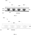
- the bending supporting portion 23 includes a bending skeleton 231 and a flexible supporting bar 232 connected to the bending skeleton 231, and the flexible supporting bar 232 is in contact with the flexible screen 1 to support the bending portion of the flexible screen 1.
- the flexible supporting bar 232 includes a supporting portion 2321 and a plurality of connecting portions 2322 that are distributed at intervals and fastened to the supporting portion 2321.
- the supporting portion 2321 is in contact with the flexible screen 1.
- the connecting portions 2322 are located on a side of the supporting portion 2321 away from the flexible screen 1, an end of the connecting portion 2322 away from the supporting portion 2321 is connected to the bending skeleton 231, and there is a specified interval between the plurality of connecting portions 2322.
- the end of the connecting portion 2322 away from the supporting portion 2321 is connected to the bending skeleton 231, so that there is at least a specified distance from a joint between the connecting portion 2322 and the bending skeleton 231 to the supporting portion 2321.
- the connecting portions 2322 are flexible connecting portions, and there is a specified interval between the plurality of connecting portions 2322. Therefore, when the foldable display apparatus is folded, the flexible screen 1 bonded to the supporting portion 2321 and the supporting portion 2321 are bent together, and relative displacement is generated between the supporting portion 2321 and the bending skeleton 231, so that no relative displacement is likely generated between the supporting portion 2321 and the flexible screen 1. This improves strength of connection between the supporting portion 2321 and the flexible screen 1, reduces a risk of degumming between the flexible screen 1 and the flexible supporting bar 232, and improves product quality of the foldable display apparatus.
- the supporting structure has the planar supporting portions and the bending supporting portion.
- This implementation is used only as a specific solution for implementing this embodiment of this application.
- the supporting structure in the technical solution of this application is applicable to all solutions in which the flexible screen has a bending region.
- the supporting structure correspondingly has the bending supporting portion.
- a structure of a part other than the bending region of the flexible screen is not limited, for example, the part may be a curved-surface region or in any shape or state, provided that the supporting structure is adapted to the structure.
- the connecting portions 2322 are connected to the bending skeleton 231.
- the connecting portions 2322 may be clamped with the bending skeleton 231, or may be fixedly connected to the bending skeleton 231, and a structure of the connecting portion 2322 may be a clamping slot 2323, or may be a fixed protrusion 2326.
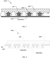
- FIG. 5 to FIG. 7 FIG. 6 is a schematic cross-sectional structural diagram of another bending supporting portion according to an embodiment of this application, and FIG. 7 is a schematic cross-sectional structural diagram of another bending supporting portion according to an embodiment of this application.
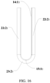
- the connecting portions 2322 are clamped with the bending skeleton 231, the connecting portions 2322 are clamping slots 2323, the bending skeleton 231 includes clamping heads 2312, and the clamping head 2312 extends into the clamping slot 2323 and is clamped with the clamping slot 2323.
- the connecting portion 2322 of the flexible supporting bar 232 is made of a flexible material. Therefore, the clamping slot 2323 is also a flexible clamping slot 2323.
- the flexible clamping slot 2323 has a slot hole 2324. There is a clamping wall 2325 on a side of the slot hole 2324 that is close to the bending skeleton 231.
- the bending skeleton 231 has the clamping heads 2312.
- the clamping head 2312 has a head 2313 and a clamping neck 2314.
- a radial size of the head 2313 of the clamping head 2312 is greater than a radial size of the clamping neck 2314, and the head 2313 of the clamping head 2312 is close to a side of the flexible supporting bar 232.
- the head 2313 of the clamping head 2312 passes through a region of the clamping wall 2325 of the clamping slot 2323, and the clamping wall 2325 elastically expands, so that the head 2313 of the clamping head 2312 passes through the region of the clamping wall 2325 to enter the slot hole 2324 of the clamping slot 2323.
- cross-sectional shapes of the clamping head and the clamping slot are not specifically limited, and a structure for clamping between the clamping head and the clamping slot is not specifically limited, either.
- the cross-sectional shape of the clamping head is a rectangle, and the clamping head is clamped with the clamping slot in a planar manner.
- the cross-sectional shape of the clamping head is an ellipse, and the clamping head is clamped with the clamping slot in a curved-surface manner.
- the clamping head has a region whose size gradually increases in a direction away from the bottom of the clamping slot, to facilitate mounting the clamping head to the clamping slot.
- the cross-sectional shape of the clamping head is a triangle.
- a size of the clamping head gradually increases in the direction away from the bottom of the clamping slot, to facilitate mounting.
- FIG. 8 is a schematic cross-sectional structural diagram of another bending supporting portion according to an embodiment of this application
- FIG. 9 is a schematic cross-sectional structural diagram of another bending supporting portion according to an embodiment of this application
- FIG. 10 is a schematic cross-sectional structural diagram of another bending supporting portion according to an embodiment of this application.
- the connecting portions 2322 may be fixed protrusions 2326, and an end of the fixed protrusion 2326 away from the supporting portion 2321 is connected to the bending skeleton 231. Therefore, there is a specified distance from the joint between the connecting portion 2322 and the bending skeleton 231 to the supporting portion 2321. Within the distance, connection is performed by using the fixed protrusion 2326.
- the fixed protrusion 2326 is flexible and has relatively high flexibility. In this way, when the foldable display apparatus is folded, the bending supporting portion 23 is bent, and the fixed protrusion 2326 is bent. Therefore, the supporting portion 2321 and the flexible screen 1 fixedly connected to the supporting portion 2321 are bent simultaneously, and no relative displacement is likely generated between the supporting portion 2321 and the flexible screen 1. In this way, this can improve strength of connection between the supporting portion 2321 and the flexible screen 1, reduce a risk of degumming between the flexible screen 1 and the flexible supporting bar 232, and improve product quality of the foldable display apparatus.
- the fixed protrusions 2326 may have fasteners
- the bending skeleton 231 has bayonets 2315
- the fasteners are in one-to-one adaptation with the bayonets 2315, namely, the fasteners may be clamped with the bayonets 2315.
- the fastener is flexible.
- the fastener may be inserted into the bayonet 2315 of the bending skeleton 231. The fastener may contract when passing through the bayonet 2315.
- the fastener returns to an original shape after passing through the bayonet 2315, and may be clamped with the bayonet 2315, so that an end of the fixed protrusion 2326 away from the supporting portion 2321 is connected to the bending skeleton 231.
- mounting can be completed by inserting the bayonet 2315 of the fixed protrusion 2326 into the bayonet 2315 of the bending skeleton 231. Therefore, a mounting process is relatively simple.
- cross-sectional shapes of the fastener and the bayonet are not specifically limited, and a structure for clamping between the fastener and the bayonet is not specifically limited, either.
- the cross-sectional shape of the fastener is a rectangle, and the fastener is clamped with the bayonet in a planar manner.
- the cross-sectional shape of the fastener is an ellipse, and the fastener is clamped with the bayonet in a curved-surface manner.
- the fastener has a region whose size gradually increases in a direction away from the bottom of the bayonet, to facilitate mounting the fastener to the bayonet.
- the cross-sectional shape of the fastener is a triangle.
- a size of the fastener gradually increases in the direction away from the bottom of the bayonet, to facilitate mounting.
- a manner for connection between the fastener and the bayonet 2315 further includes different implementation solutions.
- a structure and a shape of the bayonet 2315 are not specifically limited.
- the bayonet 2315 may be a groove 2316, or may be a through hole 2318.
- the bayonet 2315 is a groove 2316.
- An opening of the groove 2316 has a clamping edge 2317.
- the fastener may pass through the clamping edge 2317 and extends into the groove 2316, and is clamped with the clamping edge 2317.
- the fastener is a flexible fastener.
- the fastener contracts to enter the groove 2316, then returns to an original shape, and can be clamped with the clamping edge 2317, to complete mounting.
- the fastener is clamped with the groove 2316. Therefore, specified displacement may alternatively occur at a joint between the fastener and the groove 2316, to facilitate absorbing deformation of the bending supporting portion 23, and the connection manner facilitates mounting.
- the fastener is located in the groove 2316. The groove 2316 may protect the fastener, and no friction or structural interference likely occurs between a remaining structure and the fastener.
- FIG. 11 is a schematic cross-sectional structural diagram of another bending supporting portion according to an embodiment of this application.
- the bayonet 2315 is a through hole 2318, the fastener passes through the through hole 2318, and is then clamped with an edge of the through hole 2318.
- a process of mounting the fastener to the through hole 2318 is also relatively convenient, and specified displacement may alternatively occur at a joint between the fastener and the through hole 2318, to facilitate absorbing deformation of the bending supporting portion 23.
- a structure of the through hole 2318 is relatively simple, to simplify a manufacturing process of the bending skeleton 231, and reduce manufacturing costs of the bending skeleton 231.
- FIG. 12 is a schematic cross-sectional structural diagram of another bending supporting portion according to an embodiment of this application.
- the fixed protrusion 2326 may alternatively be fixedly connected to the bending skeleton 231.
- the bending skeleton 231 may include mounting portions 2319 in one-to-one adaptation with the fixed protrusions 2326. An end of the fixed protrusion 2326 away from the supporting portion 2321 is fastened to the mounting portion 2319. In this embodiment, the end of the fixed protrusion 2326 away from the supporting portion 2321 is fixedly connected to the bending skeleton 231.
- a joint between the fixed protrusion 2326 and the bending skeleton 231 is connected to the supporting portion 2321 by using the flexible fixed protrusion 2326, to absorb deformation of the bending supporting portion 23.
- strength of connection between the fixed protrusion 2326 and the bending skeleton 231 is relatively high.
- the mounting portion 2319 has a mounting hole 2320, and the fixed protrusion 2326 passes through the mounting hole 2320 and is then fastened to the bending skeleton 231.
- the fixed protrusion 2326 passes through the mounting hole 2320. Therefore, a hole wall of the mounting hole 2320 may protect the fixed protrusion 2326, to improve a service life of the fixed protrusion 2326.
- the hole wall of the mounting hole 2320 may limit the fixed protrusion 2326, to prevent excessively large displacement from being generated between the fixed protrusion 2326 and the bending skeleton 231, and improve strength of connection between the fixed protrusion 2326 and the bending skeleton 231.
- a manner for fixed connection between the fixed protrusion 2326 and the bending skeleton 231 is not limited.
- the fixed protrusion 2326 is bonded and fastened to the mounting portion 2319.
- This connection manner has relatively low costs and a relatively simple process.
- the fixed protrusion 2326 is fastened to the mounting portion 2319 in a hot-melting manner. This connection manner has relatively high strength of fixed connection, and falling-off does not likely occur.
- a shape of the connecting portion is not limited.
- the connecting portions may be bar-shaped connecting portions or dot-shaped connecting portions.
- the shape of the connecting portion may be selected based on an actual product requirement.
- FIG. 13 is a schematic structural diagram of a supporting structure according to an embodiment of this application.
- the connecting portions 2322 are bar-shaped connecting portions 2327, a quantity of bar-shaped connecting portions 2327 required by the flexible supporting bar 232 is relatively small, and a structure of the flexible supporting bar 232 is relatively simple, so that the flexible supporting bar 232 has a simple manufacturing process and relatively low manufacturing costs.
- the flexible supporting bar 232 has a plurality of bar-shaped connecting portions 2327, the bar-shaped connecting portions 2327 extend in an extension direction of the flexible supporting bar 232, and the plurality of bar-shaped connecting portions 2327 are arranged in parallel.
- a folding direction is perpendicular to the extension direction of the flexible supporting bar 232. Therefore, in this embodiment of this application, an extension direction of the bar-shaped connecting portion 2327 is perpendicular to the folding direction of the flexible supporting bar 232, so that a folding line of the foldable display apparatus is parallel to a region between the bar-shaped connecting portions 2327.
- the region between the parallel bar-shaped connecting portions 2327 can be drastically bent, to facilitate a bending operation.
- the bar-shaped connecting portions 2327 are not likely damaged. This improves a service life.
- the extension direction of the flexible supporting bar 232 is a direction A
- the folding direction is a direction B.
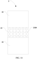
- FIG. 14 is a schematic structural diagram of another supporting structure according to an embodiment of this application.
- the connecting portions 2322 are dot-shaped connecting portions 2328
- the dot-shaped connecting portions 2328 are arranged in a matrix on the supporting portion 2321.
- the plurality of dot-shaped connecting portions 2328 arranged in a matrix can provide a relatively reliable connection relationship.
- bar-shaped gaps may be formed between the dot-shaped connecting portions 2328 that are arranged in a matrix, to facilitate a folding operation on the foldable display apparatus.
- a cross-sectional shape of the dot-shaped connecting portion in a direction parallel to the flexible screen 1 may be a circle, a square, or a polygon, and a shape of the dot-shaped connecting portion is relatively regular, to facilitate manufacturing.
- the flexible screen of the foldable display apparatus may include one bending region, or may include two or more bending regions.
- the supporting structure of the foldable display apparatus may include only one bending supporting portion, or may include two or more bending supporting portions.
- a quantity of bending regions included in the foldable display apparatus may be correspondingly the same as a quantity of included bending supporting portions, so that degumming does not likely occur between the flexible screen and the bending supporting portion of the foldable display apparatus. Therefore, strength of connection between the flexible screen and the bending supporting portion of the foldable display apparatus can be improved, and product quality of the foldable display apparatus is relatively good.
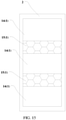
- FIG. 15 is a schematic structural diagram of a foldable display apparatus according to an embodiment of this application.
- the flexible screen 1 of the foldable display apparatus shown in the figure includes three planar regions 14 and two bending regions 15.
- FIG. 16 is a schematic diagram of a folded state of another foldable display apparatus according to an embodiment of this application.
- this application further provides a foldable display apparatus, where the foldable display apparatus includes a flexible screen 1 and the supporting structure 2 of the foldable display apparatus in any one of the foregoing technical solutions.
- the supporting structure 2 includes a bending supporting portion 23 that supports a bending region 15 of the flexible screen 1, and planar supporting portions 22 that support planar regions 14 of the flexible screen 1.
- the bending supporting portion 23 includes a flexible supporting bar 232 and a bending skeleton 231.
- the flexible supporting bar 232 includes a supporting portion 2321 and connecting portions fastened to a side of the supporting portion 2321 away from the flexible screen 1.
- Distal ends of the connecting portions are fixedly connected to the bending skeleton 231. Therefore, there may be space for relative movement between the flexible supporting bar 232 and the bending skeleton 231.
- the flexible screen 1 may be stably connected to the supporting portion of the supporting bar, and degumming does not likely occur, so that product quality of the foldable display apparatus is relatively high.
- a folding direction of the foregoing foldable display apparatus is not limited. As shown in FIG. 16 , the foldable display apparatus may be folded in a direction towards the flexible screen 1. To be specific, after being folded, the flexible screen 1 is located between supporting housings of the foldable display apparatus. Alternatively, as shown in FIG. 3 , in another specific embodiment, the foldable display apparatus may be folded in a direction away from the flexible screen 1. To be specific, after being folded, the flexible screen 1 is located on outer sides of supporting housings of the foldable display apparatus.
Landscapes
- Engineering & Computer Science (AREA)
- Theoretical Computer Science (AREA)
- Computer Hardware Design (AREA)
- Signal Processing (AREA)
- Physics & Mathematics (AREA)
- General Physics & Mathematics (AREA)
- Human Computer Interaction (AREA)
- General Engineering & Computer Science (AREA)
- Microelectronics & Electronic Packaging (AREA)
- Devices For Indicating Variable Information By Combining Individual Elements (AREA)
Applications Claiming Priority (2)
| Application Number | Priority Date | Filing Date | Title |
|---|---|---|---|
| CN201910363515.0A CN111866236B (zh) | 2019-04-30 | 2019-04-30 | 一种支撑结构及可折叠显示装置 |
| PCT/CN2020/085932 WO2020221064A1 (fr) | 2019-04-30 | 2020-04-21 | Structure de support et dispositif d'affichage pliable |
Publications (3)
| Publication Number | Publication Date |
|---|---|
| EP3944599A1 true EP3944599A1 (fr) | 2022-01-26 |
| EP3944599A4 EP3944599A4 (fr) | 2022-06-08 |
| EP3944599B1 EP3944599B1 (fr) | 2025-08-27 |
Family
ID=72965882
Family Applications (1)
| Application Number | Title | Priority Date | Filing Date |
|---|---|---|---|
| EP20798686.0A Active EP3944599B1 (fr) | 2019-04-30 | 2020-04-21 | Structure de support et dispositif d'affichage pliable |
Country Status (5)
| Country | Link |
|---|---|
| US (1) | US12250779B2 (fr) |
| EP (1) | EP3944599B1 (fr) |
| KR (1) | KR102617321B1 (fr) |
| CN (1) | CN111866236B (fr) |
| WO (1) | WO2020221064A1 (fr) |
Families Citing this family (14)
| Publication number | Priority date | Publication date | Assignee | Title |
|---|---|---|---|---|
| CN112349206B (zh) * | 2020-11-09 | 2022-07-12 | 厦门天马微电子有限公司 | 一种可折叠显示装置 |
| KR20220117373A (ko) * | 2021-02-15 | 2022-08-24 | 삼성디스플레이 주식회사 | 표시 장치 |
| CN114979322B (zh) * | 2021-02-26 | 2025-04-18 | Oppo广东移动通信有限公司 | 柔性屏组件及电子设备 |
| CN113053248B (zh) * | 2021-03-19 | 2022-09-02 | 京东方科技集团股份有限公司 | 显示模组及显示装置 |
| CN115701703B (zh) * | 2021-08-02 | 2024-05-03 | 华为技术有限公司 | 一种可折叠设备和防护器件 |
| CN116095204A (zh) * | 2021-11-08 | 2023-05-09 | Oppo广东移动通信有限公司 | 电子设备、显示屏组件、支撑组件、支撑件、制备方法 |
| CN115037817B (zh) * | 2021-11-08 | 2023-05-05 | 荣耀终端有限公司 | 凸轮组件、折叠机构、终端设备及凸轮组件的制作方法 |
| CN114038319A (zh) * | 2021-11-17 | 2022-02-11 | 合肥维信诺科技有限公司 | 可卷曲显示模组及可卷曲显示装置 |
| CN114182302A (zh) * | 2021-12-09 | 2022-03-15 | 山东清铝金属有限公司 | 一种电极板及其生产工艺 |
| CN115457862B (zh) * | 2022-08-25 | 2024-07-09 | 上海天马微电子有限公司 | 可折叠显示面板及显示装置 |
| KR20240042315A (ko) * | 2022-09-23 | 2024-04-02 | 삼성디스플레이 주식회사 | 표시 장치 |
| CN116013163B (zh) * | 2023-02-08 | 2025-01-24 | 深圳市南极光电子科技股份有限公司 | 显示面板和有源矩阵有机发光二极体显示装置 |
| CN118687058A (zh) * | 2023-03-23 | 2024-09-24 | 京东方科技集团股份有限公司 | 显示装置 |
| CN121586876A (zh) * | 2023-07-21 | 2026-02-27 | 三星电子株式会社 | 包括支撑体的电子装置 |
Family Cites Families (22)
| Publication number | Priority date | Publication date | Assignee | Title |
|---|---|---|---|---|
| DE1435791A1 (de) * | 1963-11-23 | 1969-02-20 | Jaster Geb Krupska Margarete J | Verpackung oder Ummantelung aus Kunststoff |
| US7289083B1 (en) | 2000-11-30 | 2007-10-30 | Palm, Inc. | Multi-sided display for portable computer |
| US20040170342A1 (en) * | 2003-02-28 | 2004-09-02 | 3M Innovative Properties Company | Slidable fastener bearing assembly |
| WO2011115446A2 (fr) * | 2010-03-19 | 2011-09-22 | Lee Hyung-Gon | Structure de fermeture |
| US8826499B2 (en) * | 2011-06-06 | 2014-09-09 | Nike, Inc. | Closure system |
| KR20130043526A (ko) * | 2011-10-20 | 2013-04-30 | 삼성전자주식회사 | 플렉시블 표시장치 |
| US9823696B2 (en) * | 2012-04-27 | 2017-11-21 | Nokia Technologies Oy | Limiting movement |
| KR102039172B1 (ko) | 2014-02-10 | 2019-10-31 | 삼성전자주식회사 | 사용자 단말 장치 및 이의 디스플레이 방법 |
| KR102364083B1 (ko) * | 2015-02-06 | 2022-02-17 | 엘지전자 주식회사 | 이동 단말기 |
| CN104851365B (zh) | 2015-05-28 | 2017-07-04 | 京东方科技集团股份有限公司 | 折叠显示装置 |
| KR102561880B1 (ko) * | 2015-06-03 | 2023-08-02 | 쓰리엠 이노베이티브 프로퍼티즈 컴파니 | 중립면 조정을 위한 스티프 층을 갖는 가요성 디스플레이 |
| TWI706743B (zh) * | 2015-06-03 | 2020-10-11 | 美商3M新設資產公司 | 具有互鎖裝置之撓性顯示器 |
| CN105430132B (zh) | 2015-12-29 | 2017-11-17 | 广东欧珀移动通信有限公司 | 一种可折叠终端 |
| CN106297568A (zh) * | 2016-10-31 | 2017-01-04 | 昆山国显光电有限公司 | 柔性显示装置 |
| KR102362080B1 (ko) | 2017-05-31 | 2022-02-10 | 엘지디스플레이 주식회사 | 폴더블 표시장치 |
| CN107195795B (zh) | 2017-06-07 | 2019-06-14 | 武汉天马微电子有限公司 | 可折叠显示面板和可折叠显示装置 |
| CN207115888U (zh) * | 2017-08-03 | 2018-03-16 | 深圳市柔宇科技有限公司 | 折叠机构及终端 |
| CN107437378B (zh) * | 2017-09-20 | 2020-09-11 | 上海天马微电子有限公司 | 柔性显示模组 |
| CN108712530B (zh) * | 2018-05-24 | 2020-09-22 | 维沃移动通信有限公司 | 一种铰链和移动终端 |
| CN108877529A (zh) * | 2018-07-10 | 2018-11-23 | 昆山国显光电有限公司 | 柔性显示屏盖板、柔性显示模组以及柔性显示装置 |
| CN211455155U (zh) * | 2020-01-22 | 2020-09-08 | 华为技术有限公司 | 显示模组及电子设备 |
| KR20220093569A (ko) * | 2020-12-28 | 2022-07-05 | 엘지디스플레이 주식회사 | 폴더블 표시 장치 |
-
2019
- 2019-04-30 CN CN201910363515.0A patent/CN111866236B/zh active Active
-
2020
- 2020-04-21 US US17/606,178 patent/US12250779B2/en active Active
- 2020-04-21 KR KR1020217035921A patent/KR102617321B1/ko active Active
- 2020-04-21 EP EP20798686.0A patent/EP3944599B1/fr active Active
- 2020-04-21 WO PCT/CN2020/085932 patent/WO2020221064A1/fr not_active Ceased
Also Published As
| Publication number | Publication date |
|---|---|
| WO2020221064A1 (fr) | 2020-11-05 |
| US12250779B2 (en) | 2025-03-11 |
| CN111866236B (zh) | 2021-10-26 |
| CN111866236A (zh) | 2020-10-30 |
| EP3944599A4 (fr) | 2022-06-08 |
| US20220217857A1 (en) | 2022-07-07 |
| EP3944599B1 (fr) | 2025-08-27 |
| KR102617321B1 (ko) | 2023-12-21 |
| KR20210144886A (ko) | 2021-11-30 |
Similar Documents
| Publication | Publication Date | Title |
|---|---|---|
| EP3944599B1 (fr) | Structure de support et dispositif d'affichage pliable | |
| US20190373743A1 (en) | Foldable display and foldable display device | |
| US9250379B2 (en) | Backlight module | |
| KR100603838B1 (ko) | 액정 표시장치 | |
| EP4407592A1 (fr) | Dispositif électronique | |
| CN110491283A (zh) | 一种无边框显示装置 | |
| CN101649974A (zh) | 背光模组 | |
| CN102621740B (zh) | 显示装置及其保护结构 | |
| JP5599569B2 (ja) | 裸眼立体視ディスプレイ | |
| KR20150012772A (ko) | 접이식 디스플레이 장치의 접이 방법 | |
| US9383598B2 (en) | Liquid crystal module | |
| CN213876233U (zh) | 背光模组、显示面板和显示装置 | |
| CN210573109U (zh) | 显示面板和显示装置 | |
| CN217718217U (zh) | 一种带压圈的镜头结构 | |
| US10203552B2 (en) | Rubber frame and manufacturing method thereof, backlight module, and display device and assembling method thereof | |
| CN217181373U (zh) | 显示模组及显示装置 | |
| EP4340557A1 (fr) | Dispositif électronique et procédé d'assemblage pour dispositif électronique | |
| CN212435742U (zh) | 装配结构和终端设备 | |
| US20240057446A1 (en) | Foldable display and terminal device | |
| CN210467104U (zh) | 一种显示屏 | |
| KR20210016138A (ko) | 디스플레이 장치의 패널 폴딩부재 및 이를 구비하는 접이식 디스플레이 장치 | |
| US20140028949A1 (en) | Liquid Crystal Display Device, Backlight Module, and Backboard Structure | |
| CN207336995U (zh) | 一种液晶显示模组和中胶框 | |
| CN214474774U (zh) | 一种一体化硬盘托架 | |
| CN222321565U (zh) | 折叠式电子设备 |
Legal Events
| Date | Code | Title | Description |
|---|---|---|---|
| STAA | Information on the status of an ep patent application or granted ep patent |
Free format text: STATUS: THE INTERNATIONAL PUBLICATION HAS BEEN MADE |
|
| PUAI | Public reference made under article 153(3) epc to a published international application that has entered the european phase |
Free format text: ORIGINAL CODE: 0009012 |
|
| STAA | Information on the status of an ep patent application or granted ep patent |
Free format text: STATUS: REQUEST FOR EXAMINATION WAS MADE |
|
| 17P | Request for examination filed |
Effective date: 20211021 |
|
| AK | Designated contracting states |
Kind code of ref document: A1 Designated state(s): AL AT BE BG CH CY CZ DE DK EE ES FI FR GB GR HR HU IE IS IT LI LT LU LV MC MK MT NL NO PL PT RO RS SE SI SK SM TR |
|
| A4 | Supplementary search report drawn up and despatched |
Effective date: 20220510 |
|
| RIC1 | Information provided on ipc code assigned before grant |
Ipc: G06F 1/16 20060101ALI20220504BHEP Ipc: G09F 9/30 20060101ALI20220504BHEP Ipc: H04M 1/02 20060101AFI20220504BHEP |
|
| DAV | Request for validation of the european patent (deleted) | ||
| DAX | Request for extension of the european patent (deleted) | ||
| STAA | Information on the status of an ep patent application or granted ep patent |
Free format text: STATUS: EXAMINATION IS IN PROGRESS |
|
| 17Q | First examination report despatched |
Effective date: 20240425 |
|
| GRAP | Despatch of communication of intention to grant a patent |
Free format text: ORIGINAL CODE: EPIDOSNIGR1 |
|
| STAA | Information on the status of an ep patent application or granted ep patent |
Free format text: STATUS: GRANT OF PATENT IS INTENDED |
|
| INTG | Intention to grant announced |
Effective date: 20250411 |
|
| GRAS | Grant fee paid |
Free format text: ORIGINAL CODE: EPIDOSNIGR3 |
|
| GRAA | (expected) grant |
Free format text: ORIGINAL CODE: 0009210 |
|
| STAA | Information on the status of an ep patent application or granted ep patent |
Free format text: STATUS: THE PATENT HAS BEEN GRANTED |
|
| AK | Designated contracting states |
Kind code of ref document: B1 Designated state(s): AL AT BE BG CH CY CZ DE DK EE ES FI FR GB GR HR HU IE IS IT LI LT LU LV MC MK MT NL NO PL PT RO RS SE SI SK SM TR |
|
| REG | Reference to a national code |
Ref country code: CH Ref legal event code: EP |
|
| REG | Reference to a national code |
Ref country code: DE Ref legal event code: R096 Ref document number: 602020057523 Country of ref document: DE |
|
| REG | Reference to a national code |
Ref country code: IE Ref legal event code: FG4D |
|
| REG | Reference to a national code |
Ref country code: NL Ref legal event code: MP Effective date: 20250827 |
|
| PG25 | Lapsed in a contracting state [announced via postgrant information from national office to epo] |
Ref country code: IS Free format text: LAPSE BECAUSE OF FAILURE TO SUBMIT A TRANSLATION OF THE DESCRIPTION OR TO PAY THE FEE WITHIN THE PRESCRIBED TIME-LIMIT Effective date: 20251227 |
|
| PG25 | Lapsed in a contracting state [announced via postgrant information from national office to epo] |
Ref country code: NO Free format text: LAPSE BECAUSE OF FAILURE TO SUBMIT A TRANSLATION OF THE DESCRIPTION OR TO PAY THE FEE WITHIN THE PRESCRIBED TIME-LIMIT Effective date: 20251127 |
|
| REG | Reference to a national code |
Ref country code: LT Ref legal event code: MG9D |
|
| PG25 | Lapsed in a contracting state [announced via postgrant information from national office to epo] |
Ref country code: PT Free format text: LAPSE BECAUSE OF FAILURE TO SUBMIT A TRANSLATION OF THE DESCRIPTION OR TO PAY THE FEE WITHIN THE PRESCRIBED TIME-LIMIT Effective date: 20251229 |
|
| PG25 | Lapsed in a contracting state [announced via postgrant information from national office to epo] |
Ref country code: FI Free format text: LAPSE BECAUSE OF FAILURE TO SUBMIT A TRANSLATION OF THE DESCRIPTION OR TO PAY THE FEE WITHIN THE PRESCRIBED TIME-LIMIT Effective date: 20250827 |
|
| PG25 | Lapsed in a contracting state [announced via postgrant information from national office to epo] |
Ref country code: NL Free format text: LAPSE BECAUSE OF FAILURE TO SUBMIT A TRANSLATION OF THE DESCRIPTION OR TO PAY THE FEE WITHIN THE PRESCRIBED TIME-LIMIT Effective date: 20250827 Ref country code: HR Free format text: LAPSE BECAUSE OF FAILURE TO SUBMIT A TRANSLATION OF THE DESCRIPTION OR TO PAY THE FEE WITHIN THE PRESCRIBED TIME-LIMIT Effective date: 20250827 |
|
| PG25 | Lapsed in a contracting state [announced via postgrant information from national office to epo] |
Ref country code: GR Free format text: LAPSE BECAUSE OF FAILURE TO SUBMIT A TRANSLATION OF THE DESCRIPTION OR TO PAY THE FEE WITHIN THE PRESCRIBED TIME-LIMIT Effective date: 20251128 |
|
| PG25 | Lapsed in a contracting state [announced via postgrant information from national office to epo] |
Ref country code: SE Free format text: LAPSE BECAUSE OF FAILURE TO SUBMIT A TRANSLATION OF THE DESCRIPTION OR TO PAY THE FEE WITHIN THE PRESCRIBED TIME-LIMIT Effective date: 20250827 |
|
| PG25 | Lapsed in a contracting state [announced via postgrant information from national office to epo] |
Ref country code: LV Free format text: LAPSE BECAUSE OF FAILURE TO SUBMIT A TRANSLATION OF THE DESCRIPTION OR TO PAY THE FEE WITHIN THE PRESCRIBED TIME-LIMIT Effective date: 20250827 |
|
| PG25 | Lapsed in a contracting state [announced via postgrant information from national office to epo] |
Ref country code: BG Free format text: LAPSE BECAUSE OF FAILURE TO SUBMIT A TRANSLATION OF THE DESCRIPTION OR TO PAY THE FEE WITHIN THE PRESCRIBED TIME-LIMIT Effective date: 20250827 Ref country code: PL Free format text: LAPSE BECAUSE OF FAILURE TO SUBMIT A TRANSLATION OF THE DESCRIPTION OR TO PAY THE FEE WITHIN THE PRESCRIBED TIME-LIMIT Effective date: 20250827 |
|
| PG25 | Lapsed in a contracting state [announced via postgrant information from national office to epo] |
Ref country code: RS Free format text: LAPSE BECAUSE OF FAILURE TO SUBMIT A TRANSLATION OF THE DESCRIPTION OR TO PAY THE FEE WITHIN THE PRESCRIBED TIME-LIMIT Effective date: 20251127 |
|
| PG25 | Lapsed in a contracting state [announced via postgrant information from national office to epo] |
Ref country code: ES Free format text: LAPSE BECAUSE OF FAILURE TO SUBMIT A TRANSLATION OF THE DESCRIPTION OR TO PAY THE FEE WITHIN THE PRESCRIBED TIME-LIMIT Effective date: 20250827 |
|
| REG | Reference to a national code |
Ref country code: AT Ref legal event code: MK05 Ref document number: 1831439 Country of ref document: AT Kind code of ref document: T Effective date: 20250827 |
|
| PG25 | Lapsed in a contracting state [announced via postgrant information from national office to epo] |
Ref country code: SM Free format text: LAPSE BECAUSE OF FAILURE TO SUBMIT A TRANSLATION OF THE DESCRIPTION OR TO PAY THE FEE WITHIN THE PRESCRIBED TIME-LIMIT Effective date: 20250827 |
|
| PGFP | Annual fee paid to national office [announced via postgrant information from national office to epo] |
Ref country code: GB Payment date: 20260312 Year of fee payment: 7 |
|
| PG25 | Lapsed in a contracting state [announced via postgrant information from national office to epo] |
Ref country code: DK Free format text: LAPSE BECAUSE OF FAILURE TO SUBMIT A TRANSLATION OF THE DESCRIPTION OR TO PAY THE FEE WITHIN THE PRESCRIBED TIME-LIMIT Effective date: 20250827 |
|
| PG25 | Lapsed in a contracting state [announced via postgrant information from national office to epo] |
Ref country code: AT Free format text: LAPSE BECAUSE OF FAILURE TO SUBMIT A TRANSLATION OF THE DESCRIPTION OR TO PAY THE FEE WITHIN THE PRESCRIBED TIME-LIMIT Effective date: 20250827 |
|
| PG25 | Lapsed in a contracting state [announced via postgrant information from national office to epo] |
Ref country code: IT Free format text: LAPSE BECAUSE OF FAILURE TO SUBMIT A TRANSLATION OF THE DESCRIPTION OR TO PAY THE FEE WITHIN THE PRESCRIBED TIME-LIMIT Effective date: 20250827 |
|
| PGFP | Annual fee paid to national office [announced via postgrant information from national office to epo] |
Ref country code: FR Payment date: 20260309 Year of fee payment: 7 |
|
| PG25 | Lapsed in a contracting state [announced via postgrant information from national office to epo] |
Ref country code: CZ Free format text: LAPSE BECAUSE OF FAILURE TO SUBMIT A TRANSLATION OF THE DESCRIPTION OR TO PAY THE FEE WITHIN THE PRESCRIBED TIME-LIMIT Effective date: 20250827 |
|
| PG25 | Lapsed in a contracting state [announced via postgrant information from national office to epo] |
Ref country code: EE Free format text: LAPSE BECAUSE OF FAILURE TO SUBMIT A TRANSLATION OF THE DESCRIPTION OR TO PAY THE FEE WITHIN THE PRESCRIBED TIME-LIMIT Effective date: 20250827 Ref country code: SK Free format text: LAPSE BECAUSE OF FAILURE TO SUBMIT A TRANSLATION OF THE DESCRIPTION OR TO PAY THE FEE WITHIN THE PRESCRIBED TIME-LIMIT Effective date: 20250827 |