EP3945024B1 - Flugzeugklimaregelungssystem - Google Patents
Flugzeugklimaregelungssystem Download PDFInfo
- Publication number
- EP3945024B1 EP3945024B1 EP21188736.9A EP21188736A EP3945024B1 EP 3945024 B1 EP3945024 B1 EP 3945024B1 EP 21188736 A EP21188736 A EP 21188736A EP 3945024 B1 EP3945024 B1 EP 3945024B1
- Authority
- EP
- European Patent Office
- Prior art keywords
- medium
- heat exchanger
- region
- turbine
- environmental control
- Prior art date
- Legal status (The legal status is an assumption and is not a legal conclusion. Google has not performed a legal analysis and makes no representation as to the accuracy of the status listed.)
- Active
Links
Images

Classifications
-
- B—PERFORMING OPERATIONS; TRANSPORTING
- B64—AIRCRAFT; AVIATION; COSMONAUTICS
- B64D—EQUIPMENT FOR FITTING IN OR TO AIRCRAFT; FLIGHT SUITS; PARACHUTES; ARRANGEMENT OR MOUNTING OF POWER PLANTS OR PROPULSION TRANSMISSIONS IN AIRCRAFT
- B64D13/00—Arrangements or adaptations of air-treatment apparatus for aircraft crew or passengers, or freight space
- B64D13/06—Arrangements or adaptations of air-treatment apparatus for aircraft crew or passengers, or freight space the air being conditioned
-
- B—PERFORMING OPERATIONS; TRANSPORTING
- B64—AIRCRAFT; AVIATION; COSMONAUTICS
- B64D—EQUIPMENT FOR FITTING IN OR TO AIRCRAFT; FLIGHT SUITS; PARACHUTES; ARRANGEMENT OR MOUNTING OF POWER PLANTS OR PROPULSION TRANSMISSIONS IN AIRCRAFT
- B64D13/00—Arrangements or adaptations of air-treatment apparatus for aircraft crew or passengers, or freight space
- B64D13/06—Arrangements or adaptations of air-treatment apparatus for aircraft crew or passengers, or freight space the air being conditioned
- B64D13/08—Arrangements or adaptations of air-treatment apparatus for aircraft crew or passengers, or freight space the air being conditioned the air being heated or cooled
-
- F—MECHANICAL ENGINEERING; LIGHTING; HEATING; WEAPONS; BLASTING
- F25—REFRIGERATION OR COOLING; COMBINED HEATING AND REFRIGERATION SYSTEMS; HEAT PUMP SYSTEMS; MANUFACTURE OR STORAGE OF ICE; LIQUEFACTION SOLIDIFICATION OF GASES
- F25B—REFRIGERATION MACHINES, PLANTS OR SYSTEMS; COMBINED HEATING AND REFRIGERATION SYSTEMS; HEAT PUMP SYSTEMS
- F25B9/00—Compression machines, plants or systems, in which the refrigerant is air or other gas of low boiling point
- F25B9/002—Compression machines, plants or systems, in which the refrigerant is air or other gas of low boiling point characterised by the refrigerant
- F25B9/004—Compression machines, plants or systems, in which the refrigerant is air or other gas of low boiling point characterised by the refrigerant the refrigerant being air
-
- F—MECHANICAL ENGINEERING; LIGHTING; HEATING; WEAPONS; BLASTING
- F25—REFRIGERATION OR COOLING; COMBINED HEATING AND REFRIGERATION SYSTEMS; HEAT PUMP SYSTEMS; MANUFACTURE OR STORAGE OF ICE; LIQUEFACTION SOLIDIFICATION OF GASES
- F25B—REFRIGERATION MACHINES, PLANTS OR SYSTEMS; COMBINED HEATING AND REFRIGERATION SYSTEMS; HEAT PUMP SYSTEMS
- F25B9/00—Compression machines, plants or systems, in which the refrigerant is air or other gas of low boiling point
- F25B9/06—Compression machines, plants or systems, in which the refrigerant is air or other gas of low boiling point using expanders
-
- B—PERFORMING OPERATIONS; TRANSPORTING
- B64—AIRCRAFT; AVIATION; COSMONAUTICS
- B64D—EQUIPMENT FOR FITTING IN OR TO AIRCRAFT; FLIGHT SUITS; PARACHUTES; ARRANGEMENT OR MOUNTING OF POWER PLANTS OR PROPULSION TRANSMISSIONS IN AIRCRAFT
- B64D13/00—Arrangements or adaptations of air-treatment apparatus for aircraft crew or passengers, or freight space
- B64D13/06—Arrangements or adaptations of air-treatment apparatus for aircraft crew or passengers, or freight space the air being conditioned
- B64D2013/0603—Environmental Control Systems
- B64D2013/0618—Environmental Control Systems with arrangements for reducing or managing bleed air, using another air source, e.g. ram air
-
- B—PERFORMING OPERATIONS; TRANSPORTING
- B64—AIRCRAFT; AVIATION; COSMONAUTICS
- B64D—EQUIPMENT FOR FITTING IN OR TO AIRCRAFT; FLIGHT SUITS; PARACHUTES; ARRANGEMENT OR MOUNTING OF POWER PLANTS OR PROPULSION TRANSMISSIONS IN AIRCRAFT
- B64D13/00—Arrangements or adaptations of air-treatment apparatus for aircraft crew or passengers, or freight space
- B64D13/06—Arrangements or adaptations of air-treatment apparatus for aircraft crew or passengers, or freight space the air being conditioned
- B64D2013/0603—Environmental Control Systems
- B64D2013/064—Environmental Control Systems comprising more than one system, e.g. dual systems
-
- B—PERFORMING OPERATIONS; TRANSPORTING
- B64—AIRCRAFT; AVIATION; COSMONAUTICS
- B64D—EQUIPMENT FOR FITTING IN OR TO AIRCRAFT; FLIGHT SUITS; PARACHUTES; ARRANGEMENT OR MOUNTING OF POWER PLANTS OR PROPULSION TRANSMISSIONS IN AIRCRAFT
- B64D13/00—Arrangements or adaptations of air-treatment apparatus for aircraft crew or passengers, or freight space
- B64D13/06—Arrangements or adaptations of air-treatment apparatus for aircraft crew or passengers, or freight space the air being conditioned
- B64D2013/0603—Environmental Control Systems
- B64D2013/0648—Environmental Control Systems with energy recovery means, e.g. using turbines
-
- B—PERFORMING OPERATIONS; TRANSPORTING
- B64—AIRCRAFT; AVIATION; COSMONAUTICS
- B64D—EQUIPMENT FOR FITTING IN OR TO AIRCRAFT; FLIGHT SUITS; PARACHUTES; ARRANGEMENT OR MOUNTING OF POWER PLANTS OR PROPULSION TRANSMISSIONS IN AIRCRAFT
- B64D13/00—Arrangements or adaptations of air-treatment apparatus for aircraft crew or passengers, or freight space
- B64D13/06—Arrangements or adaptations of air-treatment apparatus for aircraft crew or passengers, or freight space the air being conditioned
- B64D2013/0603—Environmental Control Systems
- B64D2013/0662—Environmental Control Systems with humidity control
-
- Y—GENERAL TAGGING OF NEW TECHNOLOGICAL DEVELOPMENTS; GENERAL TAGGING OF CROSS-SECTIONAL TECHNOLOGIES SPANNING OVER SEVERAL SECTIONS OF THE IPC; TECHNICAL SUBJECTS COVERED BY FORMER USPC CROSS-REFERENCE ART COLLECTIONS [XRACs] AND DIGESTS
- Y02—TECHNOLOGIES OR APPLICATIONS FOR MITIGATION OR ADAPTATION AGAINST CLIMATE CHANGE
- Y02T—CLIMATE CHANGE MITIGATION TECHNOLOGIES RELATED TO TRANSPORTATION
- Y02T50/00—Aeronautics or air transport
- Y02T50/50—On board measures aiming to increase energy efficiency
Definitions
- Embodiments of the disclosure relate to environmental control systems, and more specifically to an environmental control system of an aircraft.
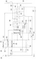
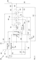
- the system 20 can receive a first medium A1 at a first inlet 22.
- the first medium A1 is bleed air, which is pressurized air originating from i.e. being "bled" from, an engine or auxiliary power unit of the aircraft. It shall be understood that one or more of the temperature, humidity, and pressure of the bleed air can vary based upon the compressor stage and revolutions per minute of the engine or auxiliary power unit from which the air is drawn.
- the system 20 is also configured to receive a second medium A2 at an inlet 24 and may provide a conditioned form of at least one of the first medium A1 and the second medium A2 to a volume 26.
- the second medium A2 is fresh air, such as outside air for example.
- the outside air can be procured via one or more scooping mechanisms, such as an impact scoop or a flush scoop for example.
- the inlet 24 can be considered a fresh or outside air inlet.
- the second medium is ram air drawn from a portion of a ram air circuit to be described in more detail below.
- the second medium A2 described herein is at an ambient pressure equal to an air pressure outside of the aircraft when the aircraft is on the ground and is between an ambient pressure and a cabin pressure when the aircraft is in flight.
- the one or more heat exchangers arranged within the shell 32 may be referred to as ram heat exchangers.
- the ram heat exchangers include a first or primary heat exchanger 34 and a second or secondary heat exchanger 36.
- ram air such as outside air for example, acts as a heat sink to cool a medium passing there through, for example the first medium A1 and/or the second medium A2.
- a fan 38 is a mechanical device that can force via push or pull methods a medium, such as ram air for example, through the shell 32 across the one or more ram heat exchangers 34, 36 at a variable cooling flow rate to control temperatures.
- the fan 38 is a separate component driven by any suitable means. Examples of such a fan include an electrically driven fan, a tip turbine fan, or a fan that is part of a simple cycle machine. However, in other embodiments, the fan 38 may part of a compression device 40 to be described in more detail below.
- the system 20 additionally includes a compression device 40.
- the compression device 40 is a mechanical device that includes components for performing thermodynamic work on a medium (e.g., extracts work from or applies work to the first medium A1, the second medium A2, and/or the third medium A3 by raising and/or lowering pressure and by raising and/or lowering temperature).
- a compression device 40 include an air cycle machine, a two-wheel air cycle machine, a three-wheel air cycle machine, a four-wheel air cycle machine, etc.
- the compression device 40 is a four-wheel air cycle machine including a compressor 42 and a plurality of turbines.
- the compressor 42 is a mechanical device configured to raise a pressure of a medium and can be driven by another mechanical device (e.g., a motor or a medium via a turbine).
- Examples of compressor types include centrifugal, diagonal or mixed-flow, axial-flow, reciprocating, ionic liquid piston, rotary screw, rotary vane, scroll, diaphragm, air bubble, etc.
- the compressor 42 is configured to receive and pressurize the second medium A2.
- the system 20 additionally includes a dehumidification system.
- the dehumidification system includes a condenser 52 and a water extractor or collector 54 arranged downstream from the condenser 52.
- the condenser 52 and the water collector 54 may be arranged in fluid communication with the second medium A2.
- the condenser 52 is a particular type of heat exchanger and the water collector 54 is a mechanical device that performs a process of removing water from a medium.
- the condenser 52 of the dehumidification system is illustrated as a separate heat exchanger located downstream from and arranged in fluid communication with an outlet of the second heat exchanger 36.
- the configuration of the at least one dehumidification system may vary.
- the condenser 52 is formed integrally with the secondary heat exchanger 36.
- the second medium A2 is configured to flow through a first portion of the heat exchanger that forms the secondary heat exchanger, and then through a second, downstream portion of the heat exchanger, which forms the condenser.
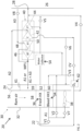
- a divider 56 wall extends parallel to the flow of ram air through the shell 32 at the interface between the first and second portions of the heat exchanger to separate the ram air shell 32 into a distinct first region 58 and second region 59.
- the fan 38 is positioned to draw ram air through only the first region 58, across the primary heat exchanger 34 and the first portion that forms a secondary heat exchanger 36.
- a fluid flow distinct from the ram air flow to be described in more detail below, is configured to flow through the second region 59, across the second portion of the heat exchanger that forms the condenser 52.
- the ram air arranged within the first region 58 and the fluid flow provided to the second region 59 do not mix within the ram air shell 32.
- Valves e.g., flow regulation device or mass flow valve
- Valves are devices that regulate, direct, and/or control a flow of a medium by opening, closing, or partially obstructing various passageways within the tubes, pipes, etc. of the system.
- Valves can be operated by actuators, such that flow rates of the medium in any portion of the system 20 can be regulated to a desired value.
- a first valve V1 may be configured to control a supply of the first medium A1 to the system 20, and a second valve may be operable to allow a portion of a medium, such as the first medium A1, to bypass the ram air circuit 30.
- operation of the second valve V2 may be used to add heat to the system 20 and to drive the compression device 40 when needed.
- a third valve V3 may be operable in the event of a pack failure, such as where the system 20 does not have a sufficient flow of the second medium A2 to meet the demands of the cabin or other loads.
- operation of valve V3 may be used to supplement the flow of second medium A2 with first medium A1, such as at a location upstream from the dehumidification system for example, to meet the demands of the aircraft.
- a fourth valve V4 may be used to allow a portion of the second medium A2 to bypass the dehumidification system and the turbine 44 of the compression device 40 and operation of a fifth valve V5 may be configured to allow a portion of the second medium A2 output from the dehumidification system to bypass the turbine 44 of the compression device 40.
- a sixth valve V6 is a surge control valve, operable to exhaust a portion of the second medium A2 output from the compressor 42 overboard or into the ram air circuit 30 to prevent a compressor surge.
- a seventh valve V7 is configured to control a supply of a medium, such as the first medium A1 for example, to the fan 38, to drive operation of the fan 38.
- a valve V8 may be configured to control a supply of the third medium A3 to the system 20,
- the system 20 is operable in a plurality of modes, selectable based on a flight condition of the aircraft.
- the system 20 may be operable in a first, low altitude mode or a second, high altitude mode.
- the first, low altitude mode is typically used for ground and low altitude flight conditions, such as ground idle, taxi, take-off, and hold conditions
- the second, high altitude mode may be used at high altitude cruise, climb, and descent flight conditions.
- valve V1 and V7 are open, and a high pressure first medium A1, such as bleed air drawn from an engine or APU, is provided to the primary heat exchanger 34 and to the fan 38.
- first medium A1 is cooled via a flow of ram air, driven by the fan 38.
- the cool first medium passes sequentially from the first heat exchanger 34 to another heat exchanger 60, where the first medium A1 is further cooled by another medium, distinct from the ram air.
- the heat exchanger 60 may be integrally formed with the heat exchanger that functions as the primary heat exchanger 34 and is positioned within the second region 59 of the ram air circuit 30.
- the further cooled first medium A1 is provided to the inlet of the bleed turbine 46.
- the high pressure first medium A1 is expanded across the bleed turbine 46 and work is extracted therefrom.
- the first medium A1 output from the bleed turbine 46 has a reduced temperature and pressure relative to the first medium A1 provided to the inlet of the bleed turbine 46.
- the first medium A1 at the outlet of the bleed turbine 46 may be used to cool the second medium A2 within the condenser 52, to be described in more detail below, and/or to cool the first medium A1 within the heat exchanger 60. This cooling may occur separately from ( FIG. 1 ) or within the second region 59 of the ram air circuit 30 ( FIG. 2 ).
- the first medium A1 may be exhausted overboard or outside the aircraft, or to a portion of the ram air circuit 30, such as downstream from all of the heat exchangers arranged therein.
- a wall or barrier 61 may be arranged at an upstream end of the second region 59 to prevent another medium, separate from the medium output from the compressing device 40 from passing through the second region 59.
- a barrier 61 is illustrated in FIG. 2 , it should be understood that any of the embodiments of the ram air system including a separate first and second region 58, 59 may include such a barrier 61.
- the work extracted form the first medium A1 in the bleed turbine 46 drives the compressor 42, which is used to compress a second medium A2 provided from an aircraft inlet 24.
- the second medium A2 such as fresh air for example, is drawn from an upstream end of the ram air circuit 30 or from another source and provided to an inlet of the compressor 42.
- the act of compressing the second medium A2 heats the second medium A2 and increases the pressure of the second medium A2.
- the compressed second medium A2 output from the compressor 42 is provided to an ozone removal heat exchanger 62, before being provided to the secondary heat exchanger 36 where it is cooled by ram air.
- the first medium A1 and the second medium A2 are configured to flow through the primary and second heat exchangers 34, 36, respectively, in the same direction relative to the ram air flow.
- embodiments where the first and second medium flow in different directions are also within the scope of the disclosure.
- the second medium A2 exiting the secondary heat exchanger 36 is then provided to the condenser 52, where the second medium A2 is further cooled by the first medium A1 output from the bleed turbine 46. From the condenser 52, the second medium A2 is provided to the water collector 54 where any free moisture is removed, to produce cool medium pressure air. This cool pressurized second medium A2 then enters the turbine 44 where work is extracted from the second medium A2 and used to drive the compressor 42. The second medium output from the turbine 44 is then sent to one or more loads of the aircraft, such as to condition the pressurized volume or cabin 26.
- valve V2 may be open to allow at least a portion of the first medium A1 to bypass the primary heat exchanger 34 and heat exchanger 60.
- Valve V2 may be operated to control, and in some embodiments, maximize the temperature of the first medium A1 provided to the bleed turbine 46.
- the work extracted from the first medium A1 within the bleed turbine 46 may be optimized while exhausting the first medium A1 therefrom with a temperature suitable to function as a heat sink with respect to the condenser 52 and/or heat exchanger 60.
- the third medium A3 such as an exhaust of cabin air for example, is recirculated to the system 20 from the pressurized volume 26, through valve V8.
- the flow of the third medium A3 may be provided directly to an inlet of the power turbine 48.
- the additional work extracted from the third medium A3 in the power turbine 48, is used in combination with the work extracted from the first medium A1 to drive the compressor 42.
- the third medium A3 may be mixed at a mixing point MP1 with the first medium A1.
- the mixing point is located downstream from an outlet of the bleed turbine 46 and the power turbine 48.
- this mixture of first medium and third medium A1+A3 may be used to cool the second medium A2 within the condenser 52, and/or to cool the first medium A1 within the heat exchanger 60, and then dumped overboard or into the ram air circuit 30.
- the compressed second medium A2 output from the compressor 42 may follow the same flow path with respect to the secondary heat exchanger 36 and condenser 52, water collector 54, and turbine 44 as previously described for the low altitude mode of operation.
- valve V5 is open in the high-altitude mode. As a result, at least a portion of the second medium A2 output from the condenser 52 bypasses the turbine 44 of the compression device.
- valve V4 is opened, thereby allowing a portion of the heated second medium A2 output from the compressor 42 to mix with the cold second medium A2 upstream from an outlet of the system 20. Accordingly, valve V4 can be controlled to achieve a second medium A2 having a desired temperature for conditioning the cabin 26.
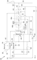
- the compression device 40 includes a second bleed turbine 46b in place of the power turbine 48. Accordingly, during both the low altitude and high-altitude modes of operation, the first medium A1 is provided to the first bleed turbine 46a then to the second bleed turbine 46b sequentially. The work extracted from the first medium A1 in both bleed turbines 46a, 46b is used to drive the compressor. Further, the first medium A1 output from the second bleed turbine 46b is used to cool the flows of medium within the condenser 52 and/or the heat exchanger 60.
- the third medium A3 is additionally provided to the system 20 and work is extracted therefrom. As shown, the third medium A3 is mixed at a mixing point MP2 with the first medium A1. In the illustrated, non-limiting embodiment, the mixing point MP2 is located downstream from an outlet of the first bleed turbine 46a and upstream from an inlet of the second bleed turbine 46b.
- the pressure ratio of one or more of the turbines of the compressing device 40 is reduced relative to existing turbines.
- the term "pressure ratio" is intended to describe the ratio of the pressure of the medium provided to an inlet of the turbine and the pressure of the medium provided at the outlet of the turbine.
- the pressure ratio of each of the turbines may be reduced compared to conventional turbines.
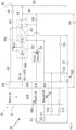
- the compression device 40 of the system 20 of FIGS. 5 and 6 includes a dual entry turbine 70 in place of the power turbine or the second bleed turbine.
- the dual entry turbine 70 is configured to receive flows of different mediums.
- a dual entry turbine typically has multiple nozzles, each of which is configured to receive a distinct flow of medium at a different entry point, such that multiple flows can be received simultaneously.
- the turbine 70 can include a plurality of inlet flow paths, such as an inner flow path and an outer flow path, to enable mixing of the medium flows at the exit of the turbine 70.
- the inner flow path can be a first diameter
- the outer flow path can be a second diameter.
- the inner flow path can align with one of the first or second nozzles
- the outer flow path can align with the other of the first or second nozzles.
- one of the inlets or nozzles of the dual entry turbine 70 is arranged downstream from and in series with an outlet of the bleed turbine 46. Accordingly, during both the low altitude and high-altitude modes of operation, the first medium A1 is provided to bleed turbine 46 then to the dual entry turbine 70 sequentially. The work extracted from the first medium A1 in both the bleed turbine 46 and the dual entry turbine 70 is used to drive the compressor. Further, the first medium A1 output from the second bleed turbine 46b is used to cool the flows of medium within the condenser 52 and/or the heat exchanger 60. As previously described, in a high-altitude mode of operation, the third medium A3 is additionally provided to the system 20 and work is extracted therefrom.
- the third medium A3 may be provided to a second inlet or nozzle of the dual entry turbine 70.
- the mixing point MP3 of the third medium A3 and the first medium A1 can be at the dual entry turbine 70, such as at an outlet of the turbine 70 for example, or alternatively, may be downstream therefrom.
Landscapes
- Engineering & Computer Science (AREA)
- Health & Medical Sciences (AREA)
- General Health & Medical Sciences (AREA)
- Pulmonology (AREA)
- Aviation & Aerospace Engineering (AREA)
- Physics & Mathematics (AREA)
- Mechanical Engineering (AREA)
- Thermal Sciences (AREA)
- General Engineering & Computer Science (AREA)
- Structures Of Non-Positive Displacement Pumps (AREA)
Claims (8)
- Klimaregelungssystem eines Flugzeugs, umfassend:
einen Stauluftkreislauf (30), der Folgendes beinhaltet:einen Stauluftmantel, (32) der mindestens einen darin positionierten Wärmetauscher (34, 36) aufweist;einen Teiler (56), der innerhalb des Stauluftmantels angeordnet ist, um den Stauluftmantel in einen ersten Bereich (58) und einen zweiten Bereich (59) zu trennen, wobei der mindestens eine Wärmetauscher innerhalb sowohl des ersten Bereichs als auch des zweiten Bereichs angeordnet ist, wobei das System derart konfiguriert ist, dass Stauluft durch den ersten Bereich strömt und dass in einem Betriebsmodus bei geringer Flughöhe ein erstes Medium (A1) und in einem Betriebsmodus bei großer Flughöhe eine Kombination aus dem ersten Medium (A1) und einem dritten Medium (A3) durch den zweiten Bereich strömt;ein Entfeuchtungssystem (52, 54), das in Fluidverbindung mit dem Stauluftkreislauf angeordnet ist; undeine Verdichtungsvorrichtung (40), die in Fluidverbindung mit dem Stauluftkreislauf und dem Entfeuchtungssystem angeordnet ist, wobei die Verdichtungsvorrichtung einen Verdichter (42) und eine Turbine (46) beinhaltet;wobei das System derart konfiguriert ist, dass das erste Medium oder die Kombination aus dem ersten und dritten Medium, die durch den zweiten Bereich strömt, aus der Turbine der Verdichtungsvorrichtung ausgestoßen wird;wobei der mindestens eine Wärmetauscher (34, 36) einen ersten Abschnitt, der innerhalb des ersten Bereichs (58) angeordnet ist, und einen zweiten Abschnitt, der innerhalb des zweiten Bereichs (59) angeordnet ist, beinhaltet, wobei der zweite Abschnitt des mindestens einen Wärmetauschers integral mit dem ersten Abschnitt ausgebildet ist; undwobei das System derart konfiguriert ist, dass das erste Medium oder die Kombination aus dem ersten Medium und dem dritten Medium, die durch den zweiten Bereich strömt, über den zweiten Abschnitt des mindestens einen Wärmetauschers strömt. - Klimaregelungssystem nach Anspruch 1, wobei der zweite Abschnitt des Wärmetauschers (34, 36) ein Kondensator des Entfeuchtungssystems (52, 54) ist.
- Klimaregelungssystem nach einem der Ansprüche 1 bis 2, wobei das erste Medium (A1) Zapfluft ist.
- Klimaregelungssystem nach einem der Ansprüche 1 bis 2, wobei das erste Medium (A1) Zapfluft ist und das dritte Medium (A3) Kabinenabluft ist.
- Klimaregelungssystem nach einem der vorhergehenden Ansprüche, ferner umfassend einen innerhalb des Stauluftmantels angeordneten Lüfter (38), um die Stauluft über den mindestens einen Wärmetauscher innerhalb des ersten Bereichs (58) zu bewegen.
- Klimaregelungssystem nach Anspruch 5, wobei der Lüfter (38) von der Verdichtungsvorrichtung (40) getrennt ist.
- Klimaregelungssystem nach Anspruch 6, wobei der Lüfter (38) elektrisch betrieben wird.
- Klimaregelungssystem nach Anspruch 6, wobei der Lüfter (38) durch einen ihm zugeführten Strom eines Mediums angetrieben wird.
Applications Claiming Priority (1)
| Application Number | Priority Date | Filing Date | Title |
|---|---|---|---|
| US202063058834P | 2020-07-30 | 2020-07-30 |
Publications (2)
| Publication Number | Publication Date |
|---|---|
| EP3945024A1 EP3945024A1 (de) | 2022-02-02 |
| EP3945024B1 true EP3945024B1 (de) | 2025-01-08 |
Family
ID=77155644
Family Applications (3)
| Application Number | Title | Priority Date | Filing Date |
|---|---|---|---|
| EP21188736.9A Active EP3945024B1 (de) | 2020-07-30 | 2021-07-30 | Flugzeugklimaregelungssystem |
| EP21188762.5A Pending EP3945027A1 (de) | 2020-07-30 | 2021-07-30 | Umweltkontrollsystem (ecs) eines luftfahrzeugs |
| EP21188755.9A Pending EP3945026A1 (de) | 2020-07-30 | 2021-07-30 | Flugzeugklimaregelungssystem |
Family Applications After (2)
| Application Number | Title | Priority Date | Filing Date |
|---|---|---|---|
| EP21188762.5A Pending EP3945027A1 (de) | 2020-07-30 | 2021-07-30 | Umweltkontrollsystem (ecs) eines luftfahrzeugs |
| EP21188755.9A Pending EP3945026A1 (de) | 2020-07-30 | 2021-07-30 | Flugzeugklimaregelungssystem |
Country Status (2)
| Country | Link |
|---|---|
| US (4) | US11939065B2 (de) |
| EP (3) | EP3945024B1 (de) |
Families Citing this family (10)
| Publication number | Priority date | Publication date | Assignee | Title |
|---|---|---|---|---|
| DE102018126921A1 (de) * | 2018-10-29 | 2020-04-30 | Airbus Operations Gmbh | Flugzeugkälteanlage mit einer motor-unterstützten Kabinenabluftturbine |
| FR3103140B1 (fr) * | 2019-11-19 | 2021-10-22 | Liebherr Aerospace Toulouse Sas | Système de conditionnement d’air d’une cabine d’un véhicule de transport aérien ou ferroviaire utilisant une source d’air pneumatique et thermique distincte de la source d’air de conditionnement |
| US12214888B2 (en) | 2020-07-30 | 2025-02-04 | Hamilton Sundstrand Corporation | Aircraft environmental control system |
| EP3945031B1 (de) | 2020-07-30 | 2024-01-31 | Hamilton Sundstrand Corporation | Flugzeugklimaregelungssystem |
| US11939065B2 (en) | 2020-07-30 | 2024-03-26 | Hamilton Sundstrand Corporation | Aircraft environmental control system |
| US20220363397A1 (en) * | 2021-05-11 | 2022-11-17 | Gulfstream Aerospace Corporation | Vehicles, humidification systems for a vehicle, and methods for humidifying an interior of a vehicle |
| US12595065B2 (en) * | 2022-05-02 | 2026-04-07 | Hamilton Sundstrand Corporation | 100% ambient air environmental control system |
| KR20240074256A (ko) | 2022-11-21 | 2024-05-28 | 현대자동차주식회사 | 항공기의 환경 제어 장치 및 이의 작동 방법 |
| KR20240141454A (ko) * | 2023-03-20 | 2024-09-27 | 현대자동차주식회사 | 항공기의 온도 및 압력 제어 장치 |
| US20250074601A1 (en) * | 2023-09-05 | 2025-03-06 | Hamilton Sundstrand Corporation | Less bleed environmental control system |
Family Cites Families (70)
| Publication number | Priority date | Publication date | Assignee | Title |
|---|---|---|---|---|
| US2777301A (en) * | 1952-06-30 | 1957-01-15 | Garrett Corp | All-purpose power and air conditioning system |
| US4419926A (en) | 1980-09-02 | 1983-12-13 | Lockheed Corporation | ESC energy recovery system for fuel-efficient aircraft |
| US4374469A (en) * | 1980-12-24 | 1983-02-22 | United Technologies Corporation | Variable capacity air cycle refrigeration system |
| US5025642A (en) * | 1990-02-20 | 1991-06-25 | Allied-Signal Inc. | Fluid conditioning apparatus and system |
| US5299763A (en) | 1991-12-23 | 1994-04-05 | Allied-Signal Inc. | Aircraft cabin air conditioning system with improved fresh air supply |
| US5442905A (en) | 1994-04-08 | 1995-08-22 | Alliedsignal Inc. | Integrated power and cooling environmental control system |
| US5461882A (en) * | 1994-07-22 | 1995-10-31 | United Technologies Corporation | Regenerative condensing cycle |
| US5899085A (en) | 1997-08-01 | 1999-05-04 | Mcdonnell Douglas Corporation | Integrated air conditioning and power unit |
| US5887445A (en) | 1997-11-11 | 1999-03-30 | Alliedsignal Inc. | Two spool environmental control system |
| US6148622A (en) | 1998-04-03 | 2000-11-21 | Alliedsignal Inc. | Environmental control system no condenser high pressure water separation system |
| US6128909A (en) * | 1998-06-04 | 2000-10-10 | Alliedsignal Inc. | Air cycle environmental control systems with two stage compression and expansion and separate ambient air fan |
| US6199387B1 (en) * | 1999-07-30 | 2001-03-13 | Liebherr-Aerospace Lindenberg Gmbh | Air-conditioning system for airplane cabin |
| US6250097B1 (en) * | 1999-10-12 | 2001-06-26 | Alliedsignal Inc. | Dual expansion energy recovery (DEER) air cycle system with mid pressure water separation |
| DE19963280C1 (de) | 1999-12-27 | 2001-08-23 | Liebherr Aerospace Gmbh | Klimatisierungssystem für Flugzeugkabinen |
| US6427471B1 (en) * | 2000-02-29 | 2002-08-06 | Shimadzu Corporation | Air cycle machine and air conditioning system using the same |
| JP4211196B2 (ja) * | 2000-05-19 | 2009-01-21 | 株式会社島津製作所 | 航空機用空気調和装置 |
| US6655168B2 (en) * | 2001-07-05 | 2003-12-02 | Shimadzu Corporation | Aircraft air conditioner |
| US6526775B1 (en) | 2001-09-14 | 2003-03-04 | The Boeing Company | Electric air conditioning system for an aircraft |
| DE10201426B8 (de) | 2002-01-16 | 2004-09-02 | Liebherr-Aerospace Lindenberg Gmbh | Klimatisierungssystem |
| EP1492704B1 (de) | 2002-04-08 | 2006-12-06 | Honeywell Normalair-Garrett (Holdings) Limited | Klimaanlage |
| US6684660B1 (en) | 2002-08-08 | 2004-02-03 | Hamilton Sundstrand | Pneumatic cabin super charger |
| GB2398864B (en) | 2003-01-23 | 2006-02-22 | Honeywell Normalair Garrett | Air conditioning system and method of testing |
| JP4144475B2 (ja) | 2003-08-22 | 2008-09-03 | 株式会社島津製作所 | 空調装置 |
| GB0414341D0 (en) * | 2004-06-26 | 2004-07-28 | Honeywell Normalair Garrett | Closed loop air conditioning system |
| US7578136B2 (en) | 2004-08-23 | 2009-08-25 | Honeywell International Inc. | Integrated power and pressurization system |
| JP2006078092A (ja) | 2004-09-10 | 2006-03-23 | Kawasaki Heavy Ind Ltd | 空気サイクル空調システム |
| US7673459B2 (en) | 2006-04-05 | 2010-03-09 | General Electric Company | System and method for providing air to a compressor of an aircraft auxiliary gas turbine engine |
| US9481468B1 (en) | 2011-07-22 | 2016-11-01 | Peter Schiff | Aircraft environmental control system |
| US9555893B2 (en) | 2011-11-28 | 2017-01-31 | Hamilton Sundstrand Corporation | Blended flow air cycle system for environmental control |
| US9669936B1 (en) | 2012-10-24 | 2017-06-06 | The Boeing Company | Aircraft air conditioning systems and methods |
| GB201318572D0 (en) | 2013-10-21 | 2013-12-04 | Rolls Royce Plc | Pneumatic system for an aircraft |
| US9656755B2 (en) * | 2013-12-13 | 2017-05-23 | The Boeing Company | Air cycle machine pack system and method for improving low inlet pressure cooling performance |
| EP2937287B1 (de) | 2014-04-24 | 2018-02-21 | Louis J. Bruno | Klimaregelungssystem mit shoestring-kreislauf zur maximierung der effizienz |
| US20150314878A1 (en) | 2014-05-02 | 2015-11-05 | Hamilton Sundstrand Corporation | Aircraft environmental conditioning system and method |
| EP2947012B1 (de) | 2014-05-19 | 2017-07-05 | Airbus Operations GmbH | Flugzeugklimaanlage und Verfahren für deren Betrieb |
| EP2998223B1 (de) | 2014-09-19 | 2018-12-05 | Airbus Operations GmbH | Flugzeugklimaanlage und Verfahren für den Betrieb einer Flugzeugklimaanlage |
| US10549860B2 (en) | 2014-11-25 | 2020-02-04 | Hamilton Sundstrand Corporation | Environmental control system utilizing cabin air to drive a power turbine of an air cycle machine |
| WO2016170141A1 (en) | 2015-04-23 | 2016-10-27 | Airbus Operations Gmbh | Electrically driven aircraft air conditioning system and method for operating such an aircraft air conditioning system |
| US10160547B2 (en) | 2015-05-26 | 2018-12-25 | Hamilton Sundstrand Corporation | Aircraft environmental control system |
| US10207809B2 (en) | 2015-08-31 | 2019-02-19 | Honeywell International Inc. | Integrated air and vapor cycle cooling system |
| DE102016204911A1 (de) | 2016-03-24 | 2017-09-28 | Airbus Operations Gmbh | Flugzeugklimaanlage mit einem elektrisch angetriebenen Umgebungsluftkompressor und Verfahren zum Betreiben einer derartigen Flugzeugklimaanlage |
| US11047237B2 (en) * | 2016-05-26 | 2021-06-29 | Hamilton Sunstrand Corporation | Mixing ram and bleed air in a dual entry turbine system |
| US10604263B2 (en) | 2016-05-26 | 2020-03-31 | Hamilton Sundstrand Corporation | Mixing bleed and ram air using a dual use turbine system |
| EP3248879B1 (de) | 2016-05-26 | 2021-06-30 | Hamilton Sundstrand Corporation | Mischen von zapf- und stauluft unter verwendung einer luftkreislaufmaschine mit zwei turbinen |
| US10144517B2 (en) * | 2016-05-26 | 2018-12-04 | Hamilton Sundstrand Corporation | Mixing bleed and ram air using a two turbine architecture with an outflow heat exchanger |
| EP3248876B1 (de) | 2016-05-26 | 2023-04-26 | Hamilton Sundstrand Corporation | Mischen von zapf- und stau-luft an einem turbineneinlass einer komprimierungsvorrichtung |
| EP3254970B1 (de) * | 2016-05-26 | 2020-04-29 | Hamilton Sundstrand Corporation | Klimaregelungssystem mit einem abströmungswärmetauscher |
| US11377216B2 (en) | 2016-08-23 | 2022-07-05 | Ge Aviation Systems Llc | Advanced method and aircraft for pre-cooling an environmental control system using a dual compressor four wheel turbo-machine |
| US10633098B2 (en) | 2016-10-24 | 2020-04-28 | Hamilton Sundstrand Corporation | Environmental control system |
| US10745137B2 (en) | 2017-01-27 | 2020-08-18 | Hamilton Sunstrand Corporation | Advanced environmental control system in an integrated split pack arrangement with one bleed/outflow heat exchanger |
| US10822095B2 (en) * | 2017-01-27 | 2020-11-03 | Hamilton Sundstrand Corporation | Advanced environmental control system in an integrated pack arrangement with one bleed/outflow heat exchanger |
| US10239624B2 (en) | 2017-02-15 | 2019-03-26 | The Boeing Company | Reverse air cycle machine (RACM) thermal management systems and methods |
| US10384785B2 (en) | 2017-02-17 | 2019-08-20 | Hamilton Sundstrand Corporation | Two mode system that provides bleed and outside air or just outside air |
| FR3063042B1 (fr) * | 2017-02-23 | 2019-07-05 | Liebherr-Aerospace Toulouse Sas | Procede de ventilation d'un canal d'air dynamique et dispositif de controle environnemental et vehicule mettant en œuvre ce procede |
| US10526092B2 (en) | 2017-04-03 | 2020-01-07 | Hamilton Sundstrand Corporation | Turbine-assisted cabin air compressor |
| US11427331B2 (en) | 2017-04-13 | 2022-08-30 | Hamilton Sundstrand Corporation | Fresh air and recirculation air mixing optimization |
| US10850854B2 (en) | 2017-06-28 | 2020-12-01 | Hamilton Sunstrand Corporation | Three wheel and simple cycle aircraft environmental control system |
| US11254435B2 (en) | 2017-10-13 | 2022-02-22 | Hamilton Sundstrand Corporation | Supplemental pack driven by bleed air and cabin air |
| US11192655B2 (en) * | 2017-11-03 | 2021-12-07 | Hamilton Sundstrand Corporation | Regenerative system ECOECS |
| US11136130B2 (en) | 2017-11-06 | 2021-10-05 | Hamilton Sundstrand Corporation | Aircraft enviromental control system with series bleed air turbines |
| US10501191B1 (en) | 2018-01-17 | 2019-12-10 | Northrop Grumman Systems Corporation | Integrated aircraft cooling machine |
| US11053010B2 (en) | 2018-01-19 | 2021-07-06 | Hamilton Sunstrand Corporation | Aircraft environmental control system |
| US11661198B2 (en) | 2018-03-21 | 2023-05-30 | The Boeing Company | Cooling system, air conditioning pack, and method for conditioning air |
| US11084592B2 (en) | 2018-06-26 | 2021-08-10 | Hamilton Sundstrand Corporation | Aircraft environmental control system |
| US10962294B2 (en) | 2018-12-07 | 2021-03-30 | Hamilton Sundstrand Corporation | Dual pass heat exchanger with drain system |
| US11174031B2 (en) | 2019-07-01 | 2021-11-16 | Hamilton Sundstrand Corporation | Environmental control system of an aircraft |
| US11300139B2 (en) | 2019-12-09 | 2022-04-12 | Hamilton Sundstrand Corporation | Air cycle machine with cooling air flow path |
| US11939065B2 (en) | 2020-07-30 | 2024-03-26 | Hamilton Sundstrand Corporation | Aircraft environmental control system |
| US12214888B2 (en) | 2020-07-30 | 2025-02-04 | Hamilton Sundstrand Corporation | Aircraft environmental control system |
| EP3945031B1 (de) | 2020-07-30 | 2024-01-31 | Hamilton Sundstrand Corporation | Flugzeugklimaregelungssystem |
-
2021
- 2021-07-30 US US17/390,200 patent/US11939065B2/en active Active
- 2021-07-30 US US17/390,188 patent/US11999491B2/en active Active
- 2021-07-30 EP EP21188736.9A patent/EP3945024B1/de active Active
- 2021-07-30 US US17/390,167 patent/US11851190B2/en active Active
- 2021-07-30 EP EP21188762.5A patent/EP3945027A1/de active Pending
- 2021-07-30 EP EP21188755.9A patent/EP3945026A1/de active Pending
-
2024
- 2024-02-20 US US18/581,791 patent/US20240246681A1/en active Pending
Also Published As
| Publication number | Publication date |
|---|---|
| US11939065B2 (en) | 2024-03-26 |
| US11851190B2 (en) | 2023-12-26 |
| US20220033093A1 (en) | 2022-02-03 |
| US20240246681A1 (en) | 2024-07-25 |
| EP3945026A1 (de) | 2022-02-02 |
| EP3945027A1 (de) | 2022-02-02 |
| EP3945024A1 (de) | 2022-02-02 |
| US11999491B2 (en) | 2024-06-04 |
| US20220033086A1 (en) | 2022-02-03 |
| US20220033087A1 (en) | 2022-02-03 |
Similar Documents
| Publication | Publication Date | Title |
|---|---|---|
| EP3945024B1 (de) | Flugzeugklimaregelungssystem | |
| EP3945030B1 (de) | Flugzeugklimaregelungssystem | |
| EP3587269B1 (de) | Flugzeugumgebungskontrollsystem | |
| EP3945028B1 (de) | Umweltkontrollsystem (ecs) eines luftfahrzeugs | |
| EP4082911B1 (de) | 100 % umgebungsluft-klimaanlage mit in serie angeordneten zapfluftturbinen | |
| EP4036013B1 (de) | Raumluftarchitektur mit einer einzigen acm ohne umgebungsturbine | |
| EP4005925A1 (de) | Raumluftarchitektur mit einzelluftkreislaufmaschine und hochdruckwasserabscheider | |
| EP4520664A1 (de) | Umweltkontrollsystem mit verringertem ablass | |
| EP3492381A1 (de) | Mischen von zapf- und stauluft mittels einer zweiturbinenarchitektur mit einem ausflusswärmetauscher |
Legal Events
| Date | Code | Title | Description |
|---|---|---|---|
| PUAI | Public reference made under article 153(3) epc to a published international application that has entered the european phase |
Free format text: ORIGINAL CODE: 0009012 |
|
| STAA | Information on the status of an ep patent application or granted ep patent |
Free format text: STATUS: THE APPLICATION HAS BEEN PUBLISHED |
|
| AK | Designated contracting states |
Kind code of ref document: A1 Designated state(s): AL AT BE BG CH CY CZ DE DK EE ES FI FR GB GR HR HU IE IS IT LI LT LU LV MC MK MT NL NO PL PT RO RS SE SI SK SM TR |
|
| STAA | Information on the status of an ep patent application or granted ep patent |
Free format text: STATUS: REQUEST FOR EXAMINATION WAS MADE |
|
| 17P | Request for examination filed |
Effective date: 20220729 |
|
| RBV | Designated contracting states (corrected) |
Designated state(s): AL AT BE BG CH CY CZ DE DK EE ES FI FR GB GR HR HU IE IS IT LI LT LU LV MC MK MT NL NO PL PT RO RS SE SI SK SM TR |
|
| STAA | Information on the status of an ep patent application or granted ep patent |
Free format text: STATUS: EXAMINATION IS IN PROGRESS |
|
| 17Q | First examination report despatched |
Effective date: 20230523 |
|
| GRAP | Despatch of communication of intention to grant a patent |
Free format text: ORIGINAL CODE: EPIDOSNIGR1 |
|
| STAA | Information on the status of an ep patent application or granted ep patent |
Free format text: STATUS: GRANT OF PATENT IS INTENDED |
|
| INTG | Intention to grant announced |
Effective date: 20240809 |
|
| GRAS | Grant fee paid |
Free format text: ORIGINAL CODE: EPIDOSNIGR3 |
|
| GRAA | (expected) grant |
Free format text: ORIGINAL CODE: 0009210 |
|
| STAA | Information on the status of an ep patent application or granted ep patent |
Free format text: STATUS: THE PATENT HAS BEEN GRANTED |
|
| AK | Designated contracting states |
Kind code of ref document: B1 Designated state(s): AL AT BE BG CH CY CZ DE DK EE ES FI FR GB GR HR HU IE IS IT LI LT LU LV MC MK MT NL NO PL PT RO RS SE SI SK SM TR |
|
| REG | Reference to a national code |
Ref country code: GB Ref legal event code: FG4D |
|
| REG | Reference to a national code |
Ref country code: CH Ref legal event code: EP |
|
| REG | Reference to a national code |
Ref country code: DE Ref legal event code: R096 Ref document number: 602021024587 Country of ref document: DE |
|
| REG | Reference to a national code |
Ref country code: IE Ref legal event code: FG4D |
|
| REG | Reference to a national code |
Ref country code: LT Ref legal event code: MG9D |
|
| REG | Reference to a national code |
Ref country code: NL Ref legal event code: MP Effective date: 20250108 |
|
| REG | Reference to a national code |
Ref country code: AT Ref legal event code: MK05 Ref document number: 1758178 Country of ref document: AT Kind code of ref document: T Effective date: 20250108 |
|
| PG25 | Lapsed in a contracting state [announced via postgrant information from national office to epo] |
Ref country code: NL Free format text: LAPSE BECAUSE OF FAILURE TO SUBMIT A TRANSLATION OF THE DESCRIPTION OR TO PAY THE FEE WITHIN THE PRESCRIBED TIME-LIMIT Effective date: 20250108 |
|
| PG25 | Lapsed in a contracting state [announced via postgrant information from national office to epo] |
Ref country code: RS Free format text: LAPSE BECAUSE OF FAILURE TO SUBMIT A TRANSLATION OF THE DESCRIPTION OR TO PAY THE FEE WITHIN THE PRESCRIBED TIME-LIMIT Effective date: 20250408 |
|
| PG25 | Lapsed in a contracting state [announced via postgrant information from national office to epo] |
Ref country code: FI Free format text: LAPSE BECAUSE OF FAILURE TO SUBMIT A TRANSLATION OF THE DESCRIPTION OR TO PAY THE FEE WITHIN THE PRESCRIBED TIME-LIMIT Effective date: 20250108 |
|
| PG25 | Lapsed in a contracting state [announced via postgrant information from national office to epo] |
Ref country code: PL Free format text: LAPSE BECAUSE OF FAILURE TO SUBMIT A TRANSLATION OF THE DESCRIPTION OR TO PAY THE FEE WITHIN THE PRESCRIBED TIME-LIMIT Effective date: 20250108 |
|
| PG25 | Lapsed in a contracting state [announced via postgrant information from national office to epo] |
Ref country code: ES Free format text: LAPSE BECAUSE OF FAILURE TO SUBMIT A TRANSLATION OF THE DESCRIPTION OR TO PAY THE FEE WITHIN THE PRESCRIBED TIME-LIMIT Effective date: 20250108 |
|
| PGFP | Annual fee paid to national office [announced via postgrant information from national office to epo] |
Ref country code: GB Payment date: 20250619 Year of fee payment: 5 |
|
| PG25 | Lapsed in a contracting state [announced via postgrant information from national office to epo] |
Ref country code: NO Free format text: LAPSE BECAUSE OF FAILURE TO SUBMIT A TRANSLATION OF THE DESCRIPTION OR TO PAY THE FEE WITHIN THE PRESCRIBED TIME-LIMIT Effective date: 20250408 Ref country code: IS Free format text: LAPSE BECAUSE OF FAILURE TO SUBMIT A TRANSLATION OF THE DESCRIPTION OR TO PAY THE FEE WITHIN THE PRESCRIBED TIME-LIMIT Effective date: 20250508 |
|
| PG25 | Lapsed in a contracting state [announced via postgrant information from national office to epo] |
Ref country code: HR Free format text: LAPSE BECAUSE OF FAILURE TO SUBMIT A TRANSLATION OF THE DESCRIPTION OR TO PAY THE FEE WITHIN THE PRESCRIBED TIME-LIMIT Effective date: 20250108 |
|
| PG25 | Lapsed in a contracting state [announced via postgrant information from national office to epo] |
Ref country code: LV Free format text: LAPSE BECAUSE OF FAILURE TO SUBMIT A TRANSLATION OF THE DESCRIPTION OR TO PAY THE FEE WITHIN THE PRESCRIBED TIME-LIMIT Effective date: 20250108 Ref country code: PT Free format text: LAPSE BECAUSE OF FAILURE TO SUBMIT A TRANSLATION OF THE DESCRIPTION OR TO PAY THE FEE WITHIN THE PRESCRIBED TIME-LIMIT Effective date: 20250508 |
|
| PGFP | Annual fee paid to national office [announced via postgrant information from national office to epo] |
Ref country code: FR Payment date: 20250620 Year of fee payment: 5 |
|
| PG25 | Lapsed in a contracting state [announced via postgrant information from national office to epo] |
Ref country code: GR Free format text: LAPSE BECAUSE OF FAILURE TO SUBMIT A TRANSLATION OF THE DESCRIPTION OR TO PAY THE FEE WITHIN THE PRESCRIBED TIME-LIMIT Effective date: 20250409 Ref country code: BG Free format text: LAPSE BECAUSE OF FAILURE TO SUBMIT A TRANSLATION OF THE DESCRIPTION OR TO PAY THE FEE WITHIN THE PRESCRIBED TIME-LIMIT Effective date: 20250108 |
|
| PG25 | Lapsed in a contracting state [announced via postgrant information from national office to epo] |
Ref country code: AT Free format text: LAPSE BECAUSE OF FAILURE TO SUBMIT A TRANSLATION OF THE DESCRIPTION OR TO PAY THE FEE WITHIN THE PRESCRIBED TIME-LIMIT Effective date: 20250108 |
|
| PG25 | Lapsed in a contracting state [announced via postgrant information from national office to epo] |
Ref country code: SE Free format text: LAPSE BECAUSE OF FAILURE TO SUBMIT A TRANSLATION OF THE DESCRIPTION OR TO PAY THE FEE WITHIN THE PRESCRIBED TIME-LIMIT Effective date: 20250108 |
|
| PG25 | Lapsed in a contracting state [announced via postgrant information from national office to epo] |
Ref country code: SM Free format text: LAPSE BECAUSE OF FAILURE TO SUBMIT A TRANSLATION OF THE DESCRIPTION OR TO PAY THE FEE WITHIN THE PRESCRIBED TIME-LIMIT Effective date: 20250108 |
|
| REG | Reference to a national code |
Ref country code: DE Ref legal event code: R097 Ref document number: 602021024587 Country of ref document: DE |
|
| PG25 | Lapsed in a contracting state [announced via postgrant information from national office to epo] |
Ref country code: DK Free format text: LAPSE BECAUSE OF FAILURE TO SUBMIT A TRANSLATION OF THE DESCRIPTION OR TO PAY THE FEE WITHIN THE PRESCRIBED TIME-LIMIT Effective date: 20250108 |
|
| PGFP | Annual fee paid to national office [announced via postgrant information from national office to epo] |
Ref country code: DE Payment date: 20250620 Year of fee payment: 5 |
|
| PG25 | Lapsed in a contracting state [announced via postgrant information from national office to epo] |
Ref country code: CZ Free format text: LAPSE BECAUSE OF FAILURE TO SUBMIT A TRANSLATION OF THE DESCRIPTION OR TO PAY THE FEE WITHIN THE PRESCRIBED TIME-LIMIT Effective date: 20250108 Ref country code: EE Free format text: LAPSE BECAUSE OF FAILURE TO SUBMIT A TRANSLATION OF THE DESCRIPTION OR TO PAY THE FEE WITHIN THE PRESCRIBED TIME-LIMIT Effective date: 20250108 |
|
| PG25 | Lapsed in a contracting state [announced via postgrant information from national office to epo] |
Ref country code: RO Free format text: LAPSE BECAUSE OF FAILURE TO SUBMIT A TRANSLATION OF THE DESCRIPTION OR TO PAY THE FEE WITHIN THE PRESCRIBED TIME-LIMIT Effective date: 20250108 |
|
| PG25 | Lapsed in a contracting state [announced via postgrant information from national office to epo] |
Ref country code: SK Free format text: LAPSE BECAUSE OF FAILURE TO SUBMIT A TRANSLATION OF THE DESCRIPTION OR TO PAY THE FEE WITHIN THE PRESCRIBED TIME-LIMIT Effective date: 20250108 |
|
| PLBE | No opposition filed within time limit |
Free format text: ORIGINAL CODE: 0009261 |
|
| STAA | Information on the status of an ep patent application or granted ep patent |
Free format text: STATUS: NO OPPOSITION FILED WITHIN TIME LIMIT |
|
| REG | Reference to a national code |
Ref country code: CH Ref legal event code: L10 Free format text: ST27 STATUS EVENT CODE: U-0-0-L10-L00 (AS PROVIDED BY THE NATIONAL OFFICE) Effective date: 20251119 |
|
| 26N | No opposition filed |
Effective date: 20251009 |
|
| PG25 | Lapsed in a contracting state [announced via postgrant information from national office to epo] |
Ref country code: IT Free format text: LAPSE BECAUSE OF FAILURE TO SUBMIT A TRANSLATION OF THE DESCRIPTION OR TO PAY THE FEE WITHIN THE PRESCRIBED TIME-LIMIT Effective date: 20250108 |
|
| REG | Reference to a national code |
Ref country code: CH Ref legal event code: H13 Free format text: ST27 STATUS EVENT CODE: U-0-0-H10-H13 (AS PROVIDED BY THE NATIONAL OFFICE) Effective date: 20260224 |
|
| PG25 | Lapsed in a contracting state [announced via postgrant information from national office to epo] |
Ref country code: LU Free format text: LAPSE BECAUSE OF NON-PAYMENT OF DUE FEES Effective date: 20250730 |
|
| REG | Reference to a national code |
Ref country code: BE Ref legal event code: MM Effective date: 20250731 |
|
| PG25 | Lapsed in a contracting state [announced via postgrant information from national office to epo] |
Ref country code: BE Free format text: LAPSE BECAUSE OF NON-PAYMENT OF DUE FEES Effective date: 20250731 |
|
| PG25 | Lapsed in a contracting state [announced via postgrant information from national office to epo] |
Ref country code: CH Free format text: LAPSE BECAUSE OF NON-PAYMENT OF DUE FEES Effective date: 20250731 |