EP3945039B1 - Stapelbares lagersystem mit druckempfindlichem schloss - Google Patents
Stapelbares lagersystem mit druckempfindlichem schloss Download PDFInfo
- Publication number
- EP3945039B1 EP3945039B1 EP20194860.1A EP20194860A EP3945039B1 EP 3945039 B1 EP3945039 B1 EP 3945039B1 EP 20194860 A EP20194860 A EP 20194860A EP 3945039 B1 EP3945039 B1 EP 3945039B1
- Authority
- EP
- European Patent Office
- Prior art keywords
- container
- locking portion
- storage container
- locking
- area
- Prior art date
- Legal status (The legal status is an assumption and is not a legal conclusion. Google has not performed a legal analysis and makes no representation as to the accuracy of the status listed.)
- Active
Links
Images


Classifications
-
- B—PERFORMING OPERATIONS; TRANSPORTING
- B65—CONVEYING; PACKING; STORING; HANDLING THIN OR FILAMENTARY MATERIAL
- B65D—CONTAINERS FOR STORAGE OR TRANSPORT OF ARTICLES OR MATERIALS, e.g. BAGS, BARRELS, BOTTLES, BOXES, CANS, CARTONS, CRATES, DRUMS, JARS, TANKS, HOPPERS, FORWARDING CONTAINERS; ACCESSORIES, CLOSURES, OR FITTINGS THEREFOR; PACKAGING ELEMENTS; PACKAGES
- B65D21/00—Nestable, stackable or joinable containers; Containers of variable capacity
- B65D21/02—Containers specially shaped, or provided with fittings or attachments, to facilitate nesting, stacking, or joining together
- B65D21/0209—Containers specially shaped, or provided with fittings or attachments, to facilitate nesting, stacking, or joining together stackable or joined together one-upon-the-other in the upright or upside-down position
- B65D21/0228—Containers joined together by screw-, bayonet-, snap-fit or the like
-
- B—PERFORMING OPERATIONS; TRANSPORTING
- B25—HAND TOOLS; PORTABLE POWER-DRIVEN TOOLS; MANIPULATORS
- B25H—WORKSHOP EQUIPMENT, e.g. FOR MARKING-OUT WORK; STORAGE MEANS FOR WORKSHOPS
- B25H3/00—Storage means or arrangements for workshops facilitating access to, or handling of, work tools or instruments
- B25H3/02—Boxes
Definitions
- the present invention relates to a storage container system according to the preamble of claim 1.
- a storage container system is known from US 2017/121056 A1 .
- a similar storage container system is known from US 2020/025229 A1 .
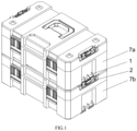
- a stackable storage container system with a pressure sensitive lock comprising of a first storage container configured and arranged to be selectively connected to a second storage container when the first storage container is on top of the second storage container.
- Each of the first container and the second container comprises a first locking portion on a bottom side of the container and a second locking portion on a top side of the container. Downward pressure on the first container causes the first locking portion of the first container and the second locking portion of the second container to engage with each other to connect the first container and the second container.
- the first locking portion comprises of a surface and the second locking portion comprises an inclined surface.
- Downward pressure on the first container causes the surface of the first locking portion of the first container and inclined surface of the second locking portion of the second container to slide against each other to connect the first container and the second container.
- the inclined surface of the second locking portion is biased against the respective first container and the second container by an elastic member so that when downward pressure on the first container causes the surface of the first locking portion of the first container and inclined surface of the second locking portion of the second container to slide against each other, the inclined surface of the second locking portion pivots outward and snaps back into place to connect the first container and the second container.
- the second locking portion can comprise of a pivot and a block combined to the pivot wherein the block comprises the inclined surface to slide against the surface of the first locking portion to connect the first container and the second container.
- the second locking portion can comprise of a mounting base securely combined to each container. A first pivot portion is combined to the mounting base. A second pivot portion is combined to the locking member. A pivot combines the first pivot portion of the mounting base and the second pivot portion of the locking member for pivot movement of the locking member with respect to the mounting base.
- the locking member further comprises of a depression for manual movement of the locking member.
- two blocks with one block on each side of the depression can be provided instead of one block. In each instance, the inclined surface of the block slides against a corresponding surface of the first locking portion.
- the present invention provides a latch mechanism configured to secure two containers together automatically, which includes a first locking portion 1 and a second locking portion 2, the first locking portion 1 and the second locking portion 2 can lock each other automatically.
- the first locking portion 1 is located at the bottom of the container, wherein the first locking portion 1 is formed with protrusion 11.
- the second locking portion 2 is located at the top of the container, wherein the second locking portion 2 includes a mounting base 21 provided with locking member 22 and elastic member 5.
- the locking member 22 can be engaged with the protrusion 11 to connected two containers by simply placing one container on top of the other and applying moderate downward pressure to the top container.
- the locking member 22 is pivotally arranged in the mounting base 21 by pivot 221, and has a locking position (please refer to Figs.1-3 ) and a release position (please refer to Fig.7 ).
- the locking member 22 switches between the locking position and the release position by rotating.
- the elastic member 5 is arranged between the locking member 22 and the mounting base 21, and the elastic member 5 biases the locking member 22 to keep it in the locking position. In other words, in the absence of external force, the locking member 22 is in the locking position due to the elasticity of the elastic member 5.
- the related structure of the elastic member 5 we will describe it later.
- first pivot portion 23 in the mounting base 21, and there is a second pivot portion 222 on the locking member 22.
- the pivot 221 pass through the first pivot portion 23 and the second pivot portion 222 to connect the locking member 22 and the mounting base 21, and the locking member 22 can rotate relative to the mounting base 21.
- the first pivot portion 23 is located in the middle of the mounting base 21, and the second pivot portion 222 includes two parts which are arranged at both ends of the locking member 22 separately.
- the first pivot portion 23 is located between the two parts of second pivot portion 222.
- first pivot portion 23 and the second pivot portion 222 can be arranged with other different quantities and arrangements, for example, only one of the first pivot portion and the second pivot portion are provided, and one is arranged on the left, the other one is arranged on the right.
- the first locking portion 1 includes two protrusions 11, wherein each protrusion 11 is provided with an opening 112 and a bottom wall 111.
- the locking member 22 of the second locking portion 2 is provided with two blocks 3.
- the blocks 3 are formed by extending from the inner surface of the locking member 22 toward the direction close to the container, which include an inclined surface 31 and a bottom surface 32, respectively.
- the locking member 22 is in locking position due to the elasticity of elastic member 5 without external force (please refer to Figs.2-3 ).
- two containers need to be connected and locked, just align one container with the other container and apply moderate downward pressure to the top container.
- the bottom wall 111 on the top container and the inclined surface 31 on the bottom container contact and resist each other.
- the bottom wall 111 push the inclined surface 31 to rotate away from the container. In other words, the bottom wall 111 pushes the blocks 3 and the locking member 22 to rotate toward the release position.
- the bottom wall 111 on the top container needs to overcome the elasticity force of the elastic member 5 on the bottom container to push the locking member 22 to rotate toward the release position.
- the top container sinks to a position that can be locked
- the bottom wall 111 on the top container and the inclined surface 31 on the bottom container no longer contact and resist each other, and the bottom wall 111 is located below the bottom surface 32 of the block 3 on the bottom container.
- the locking member 22 has been rotated to the release position.
- the elastic member 5 on the bottom container automatically rotates the locking member 22 on the bottom container back to the locking position.
- the two blocks 3 With the rotate of the locking member 22, the two blocks 3 also rotate and enter the two openings 112 on the top container respectively. When the locking member 22 returns to the locking position, the two blocks 3 also completely enter the two openings 112 on the top container respectively. In this way, the two containers are locked to each other. In short, during the locking process of the two containers, the locking member 22 will automatically complete the rotation from the locking position to the release position and then back to the locking position. Just placing one container on top of the other and applying moderate downward pressure to the top container, the two containers will lock each other automatically. It is worth noting that the application of downward force may also achieved under the natural weight of the top container.
- the bottom wall 111 is provided with a surface 1112.
- Surface 1112 can be at an angle to or parallel with the inclined surface 31 on the block 3. As shown, surface 1112 is an inclined mating surface parallel to the inclined surface 31 on block 3.
- the bottom wall 111 is provided with a hole 114
- the block 3 is provided with a protrusion (not shown) on the bottom surface 32.
- Figs.1-7 there are two protrusions 11 and two corresponding blocks 3. In other embodiment, one or more pairs of protrusion and block may also be provided.
- a depression 224 on the locking member 22 for user's fingers to enter.
- the user can rotate the locking member 22.
- the depression 224 is located between the two blocks 3.
- the user can operate the depression 224 on the bottom container to rotate the locking member 22 from the locking position to the released position.
- the locking member 22 rotates to the released position, the blocks 3 on the locking member 22 disengaged with the openings 112 on the protrusions 11 respectively, and the user can remove the top container.
- the locking member 22 on the bottom container will return to the locking position without the external force, so the user needs to operate the locking member 22 to keep it in the release position while removing the top container. It is not convenient and difficult to complete. It is necessary to provide a structure to keep the locking member 22 in a releasable position, so that the user can easily remove the top container.
- the positioning assembly 4 includes a main body 41 with a through-hole 411, a spring 43 arranged in the through-hole 411, and two ends 42 respectively arranged at both ends of the spring 43.
- the main body 41 received in the mounting portion 225 of the locking member 22.
- the connection of the main body 41 and the mounting portion 225 can be detachable, and the two also can be integrally formed.
- the two ends 42 are exposed to the through-hole 411 (or the main body 41). When pressed by external force, the two ends 42 can be hidden in the through-hole 411 (or the main body 41).
- the mounting portion 225 is located between the two blocks 3 and below the depression 224.
- both the two protrusions 11 on the top container have a side surface 113 close to the positioning assembly 4. Since the two protrusions 11 are symmetrical, only one side surface 113 on one protrusion 11 is described (though they need not be symmetrical).
- the side surface 113 is provided with a first area 61, a second area 62, and a wall 63 for separating the first area 61 and the second area 62.
- First area 61 and second area 62 provide a space for expansion of two ends 42 out of through-hole 411 by spring 43 and wall 63 serves to push two ends 42 into through-hole 411.
- First area 61 and second area 62 can also be formed as notches in side surface 113 that can take any geometrical shape as long as there is space for the arcuate path of travel of two ends 42 from rotation of locking member 22 and wall 63 separating first area 61 and second area 62 to hold locking member in respective positions.
- second area 62 can have a curved shape with a sloped edge 64. As positioning assembly 4 is moved, end 42 is biased outward by spring 43 travels against sloped edge 64. In the locking position, ends 42 are extended outward at the end of the curve furthest away from first area 61.
- positioning assembly 4 can be rotated with respect to two protrusions 11 between three positions, a locking position, a release position, and a holding position.
- the positioning assembly 4 rotates with the locking member 22. During this process, the two ends 42 of the positioning assembly 4 can move back and forth in the second area 62 along sloped edge 64 of the curve. Please refer to Fig.7 , the locking member 22 is in the release position, the blocks 3 are disengaged with the opening 112, and the ends 42 of the positioning assembly 4 are at apex 65 of sloped edge 64 of the curve closest to wall 63 separating first area 61 and second area 62.
- the elastic member 5 is a torsional spring. Both ends of the mounting base 21 are provided with a receiving recess 81 and a resisting side 811. Both ends of the locking member 22 are provided with a stopper 82. The elastic member 5 is disposed in the receiving recess 81, one end is against the resisting side 811, and the other end against the stopper 82. When the locking member 22 rotates from the locking position to the release position or holding position, the stopper 82 also rotates toward the resisting side 811. Furthermore, the stopper 82 is provided with a groove 821 for receiving the end of the elastic member 5.
- a set of limit structure are respectively provided at both ends of the mounting base 21, and symmetrical to each other. In other embodiment, only one set of limit structure can be provided at one end of the mounting base 21.
- two recesses 71 and two notches 72 are provided for receiving the two first locking portions 1 and the two second locking portions 2.
- first locking portion 1 and the second locking portion 2 can be detachably mounted on the container as separate components, or can be integrally formed with the container, also the positions of the first and second locking member on the container can be interchanged.
Landscapes
- Engineering & Computer Science (AREA)
- Mechanical Engineering (AREA)
- Stackable Containers (AREA)
Claims (13)
- Stapelbares Lagersystem, das Folgendes aufweist:einen ersten Lagerbehälter (7a), der so konfiguriert und angeordnet ist, dass er selektiv mit einem zweiten Lagerbehälter (7b) verbunden werden kann, wenn sich der erste Lagerbehälter auf dem zweiten Lagerbehälter (7b) befindet;wobei der erste Behälter (7a) und der zweite Behälter (7b) jeweils einen ersten Verriegelungsabschnitt (1) an einer Unterseite des jeweiligen ersten Behälters (7a) und zweiten Behälters (7b) sowie einen zweiten Verriegelungsabschnitt (2) an einer Oberseite des jeweiligen ersten Behälters (7a) und zweiten Behälters (7b) aufweist; undwobei ein nach unten gerichteter Druck auf den ersten Behälter (7a) bewirkt, dass der erste Verriegelungsabschnitt (1) des ersten Behälters (7a) und der zweite Verriegelungsabschnitt (2) des zweiten Behälters (7b) miteinander in Eingriff kommen, um den ersten Behälter (7a) und den zweiten Behälter (7b) zu verbinden;wobei der erste Verriegelungsabschnitt (1) einen Vorsprung (11) mit einer Öffnung (112) und einer Fläche (1112) unterhalb der Öffnung (112) aufweist und wobei der zweite Verriegelungsabschnitt (2) einen Block (3) mit einer schrägen Fläche (31) aufweist, wobei nach unten gerichteter Druck auf den ersten Vorratsbehälter (7a) bewirkt, dass die Fläche des Vorsprungs (11) des ersten Verriegelungsabschnitts (1) des ersten Vorratsbehälters (7a) und die schräge Fläche des Blocks des zweiten Verriegelungsabschnitts (2) des zweiten Vorratsbehälters (7b) gegeneinander gleiten, um den ersten Vorratsbehälter (7a) und den zweiten Vorratsbehälter (7b) zu verbinden;dadurch gekennzeichnet, dass es eine Positionierungsanordnung (4) gibt, die mit einem Verriegelungselement (22) des zweiten Verriegelungsabschnitts (2) kombiniert ist, wobei das Verriegelungselement (22) den Block (3) mit der schrägen Fläche aufweist und die Positionierungsanordnung (4) das Verriegelungselement (22) selektiv in einer Verriegelungsposition, einer Freigabeposition oder einer Halteposition hält.
- Stapelbares Lagersystem nach Anspruch 1, wobei der erste Verriegelungsabschnitt (1) eine Fläche (1112) und der zweite Verriegelungsabschnitt (2) eine schräge Fläche (31) aufweist, wobei ein nach unten gerichteter Druck auf den ersten Lagerbehälter (7a) bewirkt, dass die Fläche (1112) des ersten Verriegelungsabschnitts (1) des ersten Lagerbehälters (7a) und die schräge Fläche (31) des zweiten Verriegelungsabschnitts (2) des zweiten Vorratsbehälters (7b) gegeneinander gleiten, um den ersten Lagerbehälter (7a) und den zweiten Lagerbehälter (7b) zu verbinden.
- Stapelbares Lagersystem nach Anspruch 1 oder 2, wobei die schräge Fläche (31) des zweiten Verriegelungsabschnitts (2) durch ein elastisches Element (5) gegen den jeweiligen ersten Lagerbehälter (7a) und den zweiten Lagerbehälter (7b) vorgespannt ist, so dass die schräge Fläche (31) des zweiten Verriegelungsabschnitts (2) nach außen schwenkt und zurück an ihren Platz schnappt, um den ersten Vorratsbehälter (7a) und den zweiten Vorratsbehälter (7b) zu verbinden, wenn nach unten gerichteter Druck auf den ersten Lagerbehälter (7a) bewirkt, dass die Fläche (1112) des ersten Verriegelungsabschnitts (1) des ersten Lagerbehälters (7a) und die schräge Fläche (31) des zweiten Verriegelungsabschnitts (2) des zweiten Lagerbehälters (7b) gegeneinander gleiten.
- Stapelbares Lagersystem nach Anspruch 2 oder 3, wobei der zweite Verriegelungsabschnitt (2) eine Drehachse (221) und einen mit der Drehachse (221) verbundenen Block (3) aufweist, wobei der Block (3) die schräge Fläche (31) aufweist, um gegen die Fläche (1112) des ersten Verriegelungsabschnitts (1) zu gleiten, um den ersten Lagerbehälter (7a) und den zweiten Lagerbehälter (7b) zu verbinden, wobei vorzugsweise der zweite Verriegelungsabschnitt (2) eine Montagebasis (21) aufweist, die fest mit dem jeweiligen ersten Lagerbehälter (7a) und dem zweiten Lagerbehälter (7b) verbunden ist, sowie einen ersten Schwenkabschnitt (23), der mit der Montagebasis (21) verbunden ist, ein Verriegelungselement (22), einen zweiten Schwenkabschnitt (222), der mit dem Verriegelungselement (22) verbunden ist, und wobei die Drehachse (221) den ersten Schwenkabschnitt (23) der Montagebasis (21) und den zweiten Schwenkabschnitt (222) des Verriegelungselements (22) für eine Schwenkbewegung des Verriegelungselements (22) in Bezug auf die Montagebasis (21) verbindet.
- Stapelbares Lagersystem nach Anspruch 4, wobei das Verriegelungselement (22) ferner eine Vertiefung (224) für die manuelle Bewegung des Verriegelungselements (22) und zwei Blöcke (3) aufweist, wobei sich ein Block (3) auf jeder Seite der Vertiefung (224) befindet, wobei die zwei Blöcke (3) jeweils eine schräge Fläche (31) aufweisen, die gegen eine entsprechende Fläche (1112) des ersten Verriegelungsabschnitts (1) gleitet, vorzugsweise weiter aufweisend ein elastisches Element (5), das das Verriegelungselement (22) gegen die Montagebasis (21) vorspannt, so dass die schräge Fläche (31) des zweiten Verriegelungsabschnitts (2) des zweiten Vorratsbehälters (7b) nach außen schwenkt und wieder einschnappt, um den ersten Vorratsbehälter (7a) und den zweiten Vorratsbehälter (7b) zu verbinden, wenn nach unten gerichteter Druck auf den ersten Behälter (7a) dazu führt, dass die Fläche (1112) des ersten Verriegelungsabschnitts (1) des ersten Vorratsbehälters (7a) und die schräge Fläche (31) des zweiten Verriegelungsabschnitts (2) des zweiten Vorratsbehälters (7b) gegeneinander gleiten.
- Stapelbares Lagersystem nach Anspruch 1, dadurch gekennzeichnet, dass die Positionierungsanordnung (4) ferner ein nach außen vorgespanntes Ende (42) aufweist und der Vorsprung (11) des ersten Verriegelungsabschnitts (1) einen ersten Bereich (61) und einen zweiten Bereich (62) aufweist, die durch eine Wand (63) getrennt sind, wobei das nach außen vorgespannte Ende (42) in der Verriegelungsposition in dem zweiten Bereich (62) positioniert ist und sich das Ende (42) nach außen erstreckt, um den Block (3) des Verriegelungselements (22) in der Öffnung (112) des Vorsprungs (11) zu verriegeln, und wobei in der das nach außen vorgespannte Ende (42) in der Freigabeposition in dem zweiten Bereich (62) positioniert ist und das Ende (42) durch eine Kante des zweiten Bereichs (62) nach innen gedrückt wird.
- Stapelbares Lagersystem nach Anspruch 6, dadurch gekennzeichnet, dass das nach außen vorgespannte Ende (42) in der Halteposition in dem ersten Bereich (61) positioniert ist und sich das Ende (42) nach außen erstreckt.
- Stapelbares Lagersystem nach Anspruch 6 oder 7, dadurch gekennzeichnet, dass der zweite Bereich (62) eine gekrümmte Form besitzt.
- Stapelbares Lagersystem nach einem der Ansprüche 1 bis 8, dadurch gekennzeichnet, dass der erste Verriegelungsabschnitt (1) ein Paar von Vorsprüngen (11) mit jeweils einer Öffnung (112) und einer Fläche (1112) unterhalb der Öffnung (112) aufweist, und wobei der zweite Verriegelungsabschnitt (2) ein Paar von Blöcken (3) mit jeweils einer schrägen Fläche (31) aufweist, wobei ein nach unten gerichteter Druck auf den ersten Behälter (7a) bewirkt, dass die Flächen von jedem des Paars von Vorsprüngen (11) des ersten Verriegelungsabschnitts (1) des ersten Lagerbehälters (7a) und die schrägen Flächen (31) des Paars von Blöcken (3) des zweiten Verriegelungsabschnitts (2) des zweiten Lagerbehälters (7b) gegeneinander gleiten, um den ersten Lagerbehälter (7a) und den zweiten Lagerbehälter (7b) zu verbinden.
- Stapelbares Lagersystem nach Anspruch 9, dadurch gekennzeichnet, dass der zweite Verriegelungsabschnitt (2) ein Verriegelungselement (22) aufweist, das das Paar von Blöcken (3) und ferner eine Vertiefung (224) aufweist, die zwischen dem Paar von Blöcken (3) positioniert ist, für die manuelle Handhabung des Verriegelungselements (22), sowie eine Positionierungsanordnung (4), die zwischen dem Paar von Blöcken (3) positioniert ist, um das Verriegelungselement (22) selektiv in einer Verriegelungsposition, einer Freigabeposition oder einer Halteposition zu halten.
- Stapelbares Lagersystem nach Anspruch 10, dadurch gekennzeichnet, dass die Positionierungsanordnung (4) eine Feder (43) und ein Paar von Enden (42) aufweist, die gleichzeitig jeweils durch die Feder (43) nach außen vorgespannt sind.
- Stapelbares Lagersystem nach Anspruch 11, dadurch gekennzeichnet, dass das Paar von Vorsprüngen (11) jeweils eine innere Seitenfläche (1112) aufweist, die einander zugewandt sind, und ferner einen ersten Bereich (61) und einen zweiten Bereich (62) aufweist, die durch eine Wand (63) getrennt sind, wobei ein Paar von Enden (42) der Positionierungsanordnung (4) selektiv nach außen in den jeweiligen ersten Bereich (61) und den zweiten Bereich (62) eingreift und durch die Wand (63) nach innen gedrückt wird.
- Stapelbares Lagersystem nach Anspruch 12, dadurch gekennzeichnet, dass die nach außen vorgespannten Enden (42) in der Verriegelungsposition in dem jeweiligen zweiten Bereich (62) positioniert sind und sich das Paar der Enden (42) nach außen erstreckt, um das Paar Blöcke (3) des Verriegelungselements (22) in der Öffnung (112) des Vorsprungs (11) zu verriegeln, und wobei das nach außen vorgespannte Paar von Enden (42) in der Freigabeposition in dem zweiten Bereich (62) positioniert ist und das Paar von Enden (42) jeweils durch eine Kante des zweiten Bereichs (62) nach innen gedrückt wird, wobei der zweite Bereich (62) vorzugsweise eine gekrümmte Form aufweist.
Applications Claiming Priority (2)
| Application Number | Priority Date | Filing Date | Title |
|---|---|---|---|
| CN202010746598.4A CN111924270B (zh) | 2020-07-29 | 2020-07-29 | 自动互锁结构、储物箱、储物箱组件 |
| US17/010,975 US11155382B1 (en) | 2020-07-29 | 2020-09-03 | Stackable storage system with pressure sensitive lock |
Publications (3)
| Publication Number | Publication Date |
|---|---|
| EP3945039A1 EP3945039A1 (de) | 2022-02-02 |
| EP3945039B1 true EP3945039B1 (de) | 2023-07-05 |
| EP3945039C0 EP3945039C0 (de) | 2023-07-05 |
Family
ID=72474092
Family Applications (1)
| Application Number | Title | Priority Date | Filing Date |
|---|---|---|---|
| EP20194860.1A Active EP3945039B1 (de) | 2020-07-29 | 2020-09-07 | Stapelbares lagersystem mit druckempfindlichem schloss |
Country Status (2)
| Country | Link |
|---|---|
| EP (1) | EP3945039B1 (de) |
| AU (1) | AU2020230227B1 (de) |
Families Citing this family (2)
| Publication number | Priority date | Publication date | Assignee | Title |
|---|---|---|---|---|
| CN116408762B (zh) * | 2023-03-31 | 2025-09-26 | 宁波明良智能家居科技有限公司 | 一种堆叠工具箱 |
| US20240351183A1 (en) * | 2023-04-21 | 2024-10-24 | Kevin Boenisch | Storage System |
Family Cites Families (8)
| Publication number | Priority date | Publication date | Assignee | Title |
|---|---|---|---|---|
| DE202015005752U1 (de) * | 2015-08-18 | 2016-11-21 | Plaston Ag | Stapelbarer Koffer mit Kopplungsverbindung und Sicherung |
| DE102015013053B4 (de) * | 2015-10-08 | 2022-03-24 | Plaston Ag | Stapelbarer Koffer mit Verbindungsvorrichtung |
| US9701443B2 (en) * | 2015-11-02 | 2017-07-11 | Compass Corporation | Set of stackable tool boxes |
| DE202015106823U1 (de) * | 2015-12-15 | 2017-03-16 | Bs Systems Gmbh & Co. Kg | Behälter, Transportbox und Transportboxensystem |
| DE102016112855A1 (de) * | 2016-07-13 | 2018-01-18 | Bs Systems Gmbh & Co. Kg | Stapelbarer Systembehälter |
| DE102016112853A1 (de) * | 2016-07-13 | 2018-01-18 | Bs Systems Gmbh & Co. Kg | Stapelbarer Systembehälter |
| DE102017128493B3 (de) * | 2017-11-30 | 2018-08-16 | Bs Systems Gmbh & Co. Kg | Stapelbarer Systembehälter und Transportsystem |
| US11486427B2 (en) * | 2018-07-18 | 2022-11-01 | The Stanley Works Israel Ltd. | Stacking latch mechanism |
-
2020
- 2020-09-07 EP EP20194860.1A patent/EP3945039B1/de active Active
- 2020-09-07 AU AU2020230227A patent/AU2020230227B1/en active Active
Also Published As
| Publication number | Publication date |
|---|---|
| EP3945039C0 (de) | 2023-07-05 |
| EP3945039A1 (de) | 2022-02-02 |
| AU2020230227B1 (en) | 2021-10-21 |
Similar Documents
| Publication | Publication Date | Title |
|---|---|---|
| US11155382B1 (en) | Stackable storage system with pressure sensitive lock | |
| US12195230B2 (en) | Stackable storage system | |
| EP3945039B1 (de) | Stapelbares lagersystem mit druckempfindlichem schloss | |
| US6334346B1 (en) | Numeral lock with resettable feature | |
| EP0221749B1 (de) | Lagerungsbehälter für Aufnahmeträger | |
| US4324121A (en) | Key ring | |
| US11090820B1 (en) | Blade holder for assembling a replaceable blade | |
| CN113574724A (zh) | 电动装置 | |
| US4515424A (en) | Support structure for IC package and having removable closure | |
| US6283523B1 (en) | Safety hook with immobilizable locking lever | |
| WO2019130925A1 (ja) | 押しボタンスイッチ | |
| CN107104366A (zh) | 用于轨道安装的电气设备 | |
| CN120265526A (zh) | 一种用于固定容器的系统和方法 | |
| US6767229B1 (en) | Protective cover and electric outlet arrangement | |
| KR20080080207A (ko) | 키 배치 및 유지용 장치 | |
| KR100215604B1 (ko) | 복수의 체크카드를 저장하는 콘테이너 | |
| US20070080567A1 (en) | Child seat | |
| US20070073464A1 (en) | Safety seat assembly | |
| WO2023230852A1 (zh) | 锁接装置和组合式容器 | |
| EP1154169B1 (de) | Elektrische Steckeranordnung mit einer Bajonettverschlussverbindung | |
| CN111338434B (zh) | 硬盘托架 | |
| JPH08330023A (ja) | レバー式コネクタ | |
| EP3297099B1 (de) | Verriegelung zur verrastung einer steckdose in einem elektrischen und/oder telecommunikationsnetz | |
| US20250178221A1 (en) | Handle Holder of Blade Tool | |
| CN223836059U (zh) | 堆叠系统 |
Legal Events
| Date | Code | Title | Description |
|---|---|---|---|
| PUAI | Public reference made under article 153(3) epc to a published international application that has entered the european phase |
Free format text: ORIGINAL CODE: 0009012 |
|
| STAA | Information on the status of an ep patent application or granted ep patent |
Free format text: STATUS: THE APPLICATION HAS BEEN PUBLISHED |
|
| AK | Designated contracting states |
Kind code of ref document: A1 Designated state(s): AL AT BE BG CH CY CZ DE DK EE ES FI FR GB GR HR HU IE IS IT LI LT LU LV MC MK MT NL NO PL PT RO RS SE SI SK SM TR |
|
| STAA | Information on the status of an ep patent application or granted ep patent |
Free format text: STATUS: REQUEST FOR EXAMINATION WAS MADE |
|
| 17P | Request for examination filed |
Effective date: 20220207 |
|
| RBV | Designated contracting states (corrected) |
Designated state(s): AL AT BE BG CH CY CZ DE DK EE ES FI FR GB GR HR HU IE IS IT LI LT LU LV MC MK MT NL NO PL PT RO RS SE SI SK SM TR |
|
| GRAP | Despatch of communication of intention to grant a patent |
Free format text: ORIGINAL CODE: EPIDOSNIGR1 |
|
| STAA | Information on the status of an ep patent application or granted ep patent |
Free format text: STATUS: GRANT OF PATENT IS INTENDED |
|
| RIC1 | Information provided on ipc code assigned before grant |
Ipc: B25H 3/02 20060101ALI20230117BHEP Ipc: B65D 21/02 20060101AFI20230117BHEP |
|
| INTG | Intention to grant announced |
Effective date: 20230203 |
|
| GRAS | Grant fee paid |
Free format text: ORIGINAL CODE: EPIDOSNIGR3 |
|
| GRAA | (expected) grant |
Free format text: ORIGINAL CODE: 0009210 |
|
| STAA | Information on the status of an ep patent application or granted ep patent |
Free format text: STATUS: THE PATENT HAS BEEN GRANTED |
|
| AK | Designated contracting states |
Kind code of ref document: B1 Designated state(s): AL AT BE BG CH CY CZ DE DK EE ES FI FR GB GR HR HU IE IS IT LI LT LU LV MC MK MT NL NO PL PT RO RS SE SI SK SM TR |
|
| REG | Reference to a national code |
Ref country code: CH Ref legal event code: EP |
|
| REG | Reference to a national code |
Ref country code: AT Ref legal event code: REF Ref document number: 1584653 Country of ref document: AT Kind code of ref document: T Effective date: 20230715 |
|
| REG | Reference to a national code |
Ref country code: DE Ref legal event code: R096 Ref document number: 602020013224 Country of ref document: DE |
|
| REG | Reference to a national code |
Ref country code: IE Ref legal event code: FG4D |
|
| U01 | Request for unitary effect filed |
Effective date: 20230807 |
|
| U07 | Unitary effect registered |
Designated state(s): AT BE BG DE DK EE FI FR IT LT LU LV MT NL PT SE SI Effective date: 20230811 |
|
| REG | Reference to a national code |
Ref country code: LT Ref legal event code: MG9D |
|
| U20 | Renewal fee for the european patent with unitary effect paid |
Year of fee payment: 4 Effective date: 20230926 |
|
| PG25 | Lapsed in a contracting state [announced via postgrant information from national office to epo] |
Ref country code: GR Free format text: LAPSE BECAUSE OF FAILURE TO SUBMIT A TRANSLATION OF THE DESCRIPTION OR TO PAY THE FEE WITHIN THE PRESCRIBED TIME-LIMIT Effective date: 20231006 |
|
| PG25 | Lapsed in a contracting state [announced via postgrant information from national office to epo] |
Ref country code: ES Free format text: LAPSE BECAUSE OF FAILURE TO SUBMIT A TRANSLATION OF THE DESCRIPTION OR TO PAY THE FEE WITHIN THE PRESCRIBED TIME-LIMIT Effective date: 20230705 |
|
| PG25 | Lapsed in a contracting state [announced via postgrant information from national office to epo] |
Ref country code: IS Free format text: LAPSE BECAUSE OF FAILURE TO SUBMIT A TRANSLATION OF THE DESCRIPTION OR TO PAY THE FEE WITHIN THE PRESCRIBED TIME-LIMIT Effective date: 20231105 |
|
| PG25 | Lapsed in a contracting state [announced via postgrant information from national office to epo] |
Ref country code: RS Free format text: LAPSE BECAUSE OF FAILURE TO SUBMIT A TRANSLATION OF THE DESCRIPTION OR TO PAY THE FEE WITHIN THE PRESCRIBED TIME-LIMIT Effective date: 20230705 Ref country code: NO Free format text: LAPSE BECAUSE OF FAILURE TO SUBMIT A TRANSLATION OF THE DESCRIPTION OR TO PAY THE FEE WITHIN THE PRESCRIBED TIME-LIMIT Effective date: 20231005 Ref country code: IS Free format text: LAPSE BECAUSE OF FAILURE TO SUBMIT A TRANSLATION OF THE DESCRIPTION OR TO PAY THE FEE WITHIN THE PRESCRIBED TIME-LIMIT Effective date: 20231105 Ref country code: HR Free format text: LAPSE BECAUSE OF FAILURE TO SUBMIT A TRANSLATION OF THE DESCRIPTION OR TO PAY THE FEE WITHIN THE PRESCRIBED TIME-LIMIT Effective date: 20230705 Ref country code: GR Free format text: LAPSE BECAUSE OF FAILURE TO SUBMIT A TRANSLATION OF THE DESCRIPTION OR TO PAY THE FEE WITHIN THE PRESCRIBED TIME-LIMIT Effective date: 20231006 Ref country code: ES Free format text: LAPSE BECAUSE OF FAILURE TO SUBMIT A TRANSLATION OF THE DESCRIPTION OR TO PAY THE FEE WITHIN THE PRESCRIBED TIME-LIMIT Effective date: 20230705 |
|
| PG25 | Lapsed in a contracting state [announced via postgrant information from national office to epo] |
Ref country code: PL Free format text: LAPSE BECAUSE OF FAILURE TO SUBMIT A TRANSLATION OF THE DESCRIPTION OR TO PAY THE FEE WITHIN THE PRESCRIBED TIME-LIMIT Effective date: 20230705 |
|
| REG | Reference to a national code |
Ref country code: DE Ref legal event code: R097 Ref document number: 602020013224 Country of ref document: DE |
|
| PG25 | Lapsed in a contracting state [announced via postgrant information from national office to epo] |
Ref country code: SM Free format text: LAPSE BECAUSE OF FAILURE TO SUBMIT A TRANSLATION OF THE DESCRIPTION OR TO PAY THE FEE WITHIN THE PRESCRIBED TIME-LIMIT Effective date: 20230705 Ref country code: RO Free format text: LAPSE BECAUSE OF FAILURE TO SUBMIT A TRANSLATION OF THE DESCRIPTION OR TO PAY THE FEE WITHIN THE PRESCRIBED TIME-LIMIT Effective date: 20230705 Ref country code: CZ Free format text: LAPSE BECAUSE OF FAILURE TO SUBMIT A TRANSLATION OF THE DESCRIPTION OR TO PAY THE FEE WITHIN THE PRESCRIBED TIME-LIMIT Effective date: 20230705 Ref country code: SK Free format text: LAPSE BECAUSE OF FAILURE TO SUBMIT A TRANSLATION OF THE DESCRIPTION OR TO PAY THE FEE WITHIN THE PRESCRIBED TIME-LIMIT Effective date: 20230705 |
|
| REG | Reference to a national code |
Ref country code: CH Ref legal event code: PL |
|
| PLBE | No opposition filed within time limit |
Free format text: ORIGINAL CODE: 0009261 |
|
| STAA | Information on the status of an ep patent application or granted ep patent |
Free format text: STATUS: NO OPPOSITION FILED WITHIN TIME LIMIT |
|
| PG25 | Lapsed in a contracting state [announced via postgrant information from national office to epo] |
Ref country code: MC Free format text: LAPSE BECAUSE OF FAILURE TO SUBMIT A TRANSLATION OF THE DESCRIPTION OR TO PAY THE FEE WITHIN THE PRESCRIBED TIME-LIMIT Effective date: 20230705 |
|
| 26N | No opposition filed |
Effective date: 20240408 |
|
| REG | Reference to a national code |
Ref country code: IE Ref legal event code: MM4A |
|
| PG25 | Lapsed in a contracting state [announced via postgrant information from national office to epo] |
Ref country code: IE Free format text: LAPSE BECAUSE OF NON-PAYMENT OF DUE FEES Effective date: 20230907 |
|
| PG25 | Lapsed in a contracting state [announced via postgrant information from national office to epo] |
Ref country code: CH Free format text: LAPSE BECAUSE OF NON-PAYMENT OF DUE FEES Effective date: 20230930 |
|
| PG25 | Lapsed in a contracting state [announced via postgrant information from national office to epo] |
Ref country code: IE Free format text: LAPSE BECAUSE OF NON-PAYMENT OF DUE FEES Effective date: 20230907 Ref country code: CH Free format text: LAPSE BECAUSE OF NON-PAYMENT OF DUE FEES Effective date: 20230930 |
|
| U20 | Renewal fee for the european patent with unitary effect paid |
Year of fee payment: 5 Effective date: 20240925 |
|
| GBPC | Gb: european patent ceased through non-payment of renewal fee |
Effective date: 20240907 |
|
| PG25 | Lapsed in a contracting state [announced via postgrant information from national office to epo] |
Ref country code: GB Free format text: LAPSE BECAUSE OF NON-PAYMENT OF DUE FEES Effective date: 20240907 |
|
| PG25 | Lapsed in a contracting state [announced via postgrant information from national office to epo] |
Ref country code: CY Free format text: LAPSE BECAUSE OF FAILURE TO SUBMIT A TRANSLATION OF THE DESCRIPTION OR TO PAY THE FEE WITHIN THE PRESCRIBED TIME-LIMIT; INVALID AB INITIO Effective date: 20200907 |
|
| PG25 | Lapsed in a contracting state [announced via postgrant information from national office to epo] |
Ref country code: HU Free format text: LAPSE BECAUSE OF FAILURE TO SUBMIT A TRANSLATION OF THE DESCRIPTION OR TO PAY THE FEE WITHIN THE PRESCRIBED TIME-LIMIT; INVALID AB INITIO Effective date: 20200907 |
|
| U20 | Renewal fee for the european patent with unitary effect paid |
Year of fee payment: 6 Effective date: 20250924 |
|
| PG25 | Lapsed in a contracting state [announced via postgrant information from national office to epo] |
Ref country code: TR Free format text: LAPSE BECAUSE OF FAILURE TO SUBMIT A TRANSLATION OF THE DESCRIPTION OR TO PAY THE FEE WITHIN THE PRESCRIBED TIME-LIMIT Effective date: 20230705 |