EP3945149A1 - Procédé de fonctionnement d'une machine textile, ainsi que machine textile - Google Patents
Procédé de fonctionnement d'une machine textile, ainsi que machine textile Download PDFInfo
- Publication number
- EP3945149A1 EP3945149A1 EP21186211.5A EP21186211A EP3945149A1 EP 3945149 A1 EP3945149 A1 EP 3945149A1 EP 21186211 A EP21186211 A EP 21186211A EP 3945149 A1 EP3945149 A1 EP 3945149A1
- Authority
- EP
- European Patent Office
- Prior art keywords
- textile machine
- shut
- air flow
- suction
- work stations
- Prior art date
- Legal status (The legal status is an assumption and is not a legal conclusion. Google has not performed a legal analysis and makes no representation as to the accuracy of the status listed.)
- Withdrawn
Links
Images


Classifications
-
- D—TEXTILES; PAPER
- D01—NATURAL OR MAN-MADE THREADS OR FIBRES; SPINNING
- D01H—SPINNING OR TWISTING
- D01H11/00—Arrangements for confining or removing dust, fly or the like
- D01H11/005—Arrangements for confining or removing dust, fly or the like with blowing and/or suction devices
-
- B—PERFORMING OPERATIONS; TRANSPORTING
- B65—CONVEYING; PACKING; STORING; HANDLING THIN OR FILAMENTARY MATERIAL
- B65H—HANDLING THIN OR FILAMENTARY MATERIAL, e.g. SHEETS, WEBS, CABLES
- B65H54/00—Winding, coiling, or depositing filamentary material
- B65H54/70—Other constructional features of yarn-winding machines
- B65H54/702—Arrangements for confining or removing dust
-
- B—PERFORMING OPERATIONS; TRANSPORTING
- B65—CONVEYING; PACKING; STORING; HANDLING THIN OR FILAMENTARY MATERIAL
- B65H—HANDLING THIN OR FILAMENTARY MATERIAL, e.g. SHEETS, WEBS, CABLES
- B65H54/00—Winding, coiling, or depositing filamentary material
- B65H54/70—Other constructional features of yarn-winding machines
- B65H54/707—Suction generating system
-
- B—PERFORMING OPERATIONS; TRANSPORTING
- B65—CONVEYING; PACKING; STORING; HANDLING THIN OR FILAMENTARY MATERIAL
- B65H—HANDLING THIN OR FILAMENTARY MATERIAL, e.g. SHEETS, WEBS, CABLES
- B65H54/00—Winding, coiling, or depositing filamentary material
- B65H54/86—Arrangements for taking-up waste material before or after winding or depositing
- B65H54/88—Arrangements for taking-up waste material before or after winding or depositing by means of pneumatic arrangements, e.g. suction guns
-
- D—TEXTILES; PAPER
- D01—NATURAL OR MAN-MADE THREADS OR FIBRES; SPINNING
- D01H—SPINNING OR TWISTING
- D01H4/00—Open-end spinning machines or arrangements for imparting twist to independently moving fibres separated from slivers; Piecing arrangements therefor; Covering endless core threads with fibres by open-end spinning techniques
- D01H4/04—Open-end spinning machines or arrangements for imparting twist to independently moving fibres separated from slivers; Piecing arrangements therefor; Covering endless core threads with fibres by open-end spinning techniques imparting twist by contact of fibres with a running surface
- D01H4/06—Open-end spinning machines or arrangements for imparting twist to independently moving fibres separated from slivers; Piecing arrangements therefor; Covering endless core threads with fibres by open-end spinning techniques imparting twist by contact of fibres with a running surface co-operating with suction means
-
- B—PERFORMING OPERATIONS; TRANSPORTING
- B65—CONVEYING; PACKING; STORING; HANDLING THIN OR FILAMENTARY MATERIAL
- B65H—HANDLING THIN OR FILAMENTARY MATERIAL, e.g. SHEETS, WEBS, CABLES
- B65H2701/00—Handled material; Storage means
- B65H2701/30—Handled filamentary material
- B65H2701/31—Textiles threads or artificial strands of filaments
-
- D—TEXTILES; PAPER
- D01—NATURAL OR MAN-MADE THREADS OR FIBRES; SPINNING
- D01H—SPINNING OR TWISTING
- D01H4/00—Open-end spinning machines or arrangements for imparting twist to independently moving fibres separated from slivers; Piecing arrangements therefor; Covering endless core threads with fibres by open-end spinning techniques
- D01H4/30—Arrangements for separating slivers into fibres; Orienting or straightening fibres, e.g. using guide-rolls
- D01H4/36—Arrangements for separating slivers into fibres; Orienting or straightening fibres, e.g. using guide-rolls with means for taking away impurities
Definitions
- the present invention relates to a method for operating a textile machine, in particular a spinning or winding machine, with a large number of identical work stations arranged next to one another and with at least one suction channel which extends along the work stations, which is connected to a vacuum source and which, in regular operation, Textile machine is acted upon by a working air flow, wherein in the process of the suction channel is briefly acted upon by a cleaning air flow.
- the suction system contains at least one suction channel, which is assigned a large number of suction points and which is connected to a suction device.
- the suction system is briefly switched off at intervals by opening a large suction cross-section subjected to a strong air current.
- the suction channel has a passage which can be closed with an additional flap or a slide and has a large attachment cross-section.
- the object of the present invention is to simplify the method known from the prior art. Furthermore, a correspondingly simplified textile machine is to be proposed.
- a method for operating a textile machine in particular a spinning or winding machine, with a large number of similar work stations arranged next to one another and with at least one suction duct extending along the work stations, which is connected to a vacuum source and which, during regular operation of the textile machine, a working air flow is applied.
- the suction channel is briefly exposed to a stream of cleaning air.
- the cleaning air flow is generated by opening a shut-off element at at least several work locations from the large number of work locations, by means of which a vacuum-consuming working element and/or a vacuum-consuming maintenance element of the individual work location can be shut off from the suction duct.
- a cover element of a rotor and/or opening roller housing is opened at the several work locations in order to generate an increased cleaning air flow. As a result, a large intake opening is released at the several work locations and a correspondingly high volume flow can be provided for the cleaning air flow.
- a textile machine that has also been proposed, in particular a spinning or winding machine, has a large number of similar work stations arranged next to one another and at least one suction channel which extends along the work stations and which is connected to a vacuum source and to which a working air flow is applied during regular operation of the textile machine.
- the textile machine also has a control unit that is designed to carry out the method.
- shut-off elements at the several work stations are preferably opened simultaneously in order to generate the cleaning air flow.
- shut-off elements and/or the cover elements are located at a first end of the textile machine that faces away from the vacuum source. This can be achieved that the cleaning air flow almost the flows through the entire length of the suction channel and the suction channel is thus freed of fiber accumulations, pieces of thread and the like over its entire length.
- shut-off elements of working points which are located, for example, in a central area of the textile machine or closer to the vacuum source.
- the textile machine is designed as a rotor spinning machine, with each work station having a rotor spinning device connected to the suction channel, which can be shut off from the suction channel by means of a shut-off element.
- the shut-off elements and/or the cover elements of the rotor spinning devices are opened at the several work stations in the method.
- each of the work stations has a suction nozzle and/or a thread storage nozzle, which can be shut off from the suction channel by means of a shut-off element.
- the shut-off elements of the suction nozzles and/or the thread storage nozzles are opened at the several work stations. These are also present on the textile machine anyway and can be used advantageously to generate the cleaning air flow. If the suction nozzles and/or the thread storage nozzles are connected to a separate suction channel which is only provided for the suction nozzles and/or the thread storage nozzles, then this suction channel can be advantageously cleaned as a result.
- the cleaning air flow of the suction channel can be increased by opening the shut-off elements of the suction nozzles and/or thread storage nozzles.
- a cleaning air flow that is increased compared to the working air flow is generated.
- “increased” means that a higher volume flow is generated for the cleaning air flow than in regular operation.
- the cleaning air flow, which is increased compared to the working air flow can be generated, for example, by opening the shut-off elements of the suction nozzles and/or the yarn storage nozzles in addition to the shut-off elements of the rotor spinning devices.
- a cleaning air flow that is higher than the working air flow can be generated by opening the cover elements of the rotor spinning devices in addition to the shut-off elements of the rotor spinning devices.
- the rotor spinning devices usually have a combined rotor and opening roller housing, which is closed with a cover element.
- shut-off elements and/or the cover elements are opened after the textile machine has been started and before the start of regular operation of the textile machine.
- the regular spinning operation or the regular operation of the textile machine is not disturbed by this.
- the vacuum source is arranged at a second end of the textile machine.
- the shut-off elements and/or the cover elements are periodically opened and closed several times, so that the cleaning air flow in the suction duct is made to oscillate.
- the optimal frequency of opening and closing depends on the length of the textile machine and thus also on the suction channel. This facilitates the removal of dirt.
- At least one dirt belt suction device is also opened to generate the cleaning air flow.
- the intake cross section can be further enlarged and a high-volume cleaning air flow can thereby be generated.
- the textile machine it is correspondingly advantageous if it has at least one dirt belt suction device.
- the at least one dirt belt suction device is preferably arranged at a first end of the textile machine, which is thus remote from the vacuum source.
- figure 1 shows a schematic front view of a textile machine 1 with a suction system in a first embodiment.
- the textile machine 1 contains a large number of work stations 2 arranged next to one another, which in the present case are arranged between two frames 18 placed at the ends 9 , 17 of the textile machine 1 .
- the present textile machine 1 is designed as a spinning machine.
- Each of the work stations 2 has a feeding device 19 for feeding a fiber material to be spun, a spinning device 10 for spinning of the fiber material and a withdrawal device 20 for withdrawing the spun thread 23.
- the thread 23 is fed from the take-off device 20 to a winding device 21 where it is wound onto a spool 22 .
- the spinning machine can be designed, for example, as a rotor spinning machine and then has an opening roller as the feed device 19 and a rotor spinning device 11 as the spinning device (see Fig Figures 2 and 3 ) on.
- the spinning machine or the textile machine 1 could also be designed as an air spinning machine, the work stations 2 of which then have a drafting system as the feed device 19 and an air spinning nozzle as the spinning device 10 .
- the textile machine 1 it would also be conceivable for the textile machine 1 to be designed as a winding machine. In this case, instead of the feed device 19 and the spinning device 10, a pay-off spool would be present. In the yarn path after the take-off device 20, the different types of textile machine 1 have a largely identical structure.
- the spinning device 10 is shown as the working element 7 consuming the vacuum.
- the work station 2 can also have other working elements, including working elements 7 that use vacuum.
- several maintenance bodies including vacuum-consuming maintenance bodies 8 (see Fig Figures 2 and 3 ) to be available.
- the vacuum-consuming working elements 7 and, if present, maintenance elements 8 are each connected to a suction channel 3 and are subjected to negative pressure via this.
- the spinning devices 10 are connected to the suction duct 3 via a connecting duct 26 .
- the spinning devices 10 can each be blocked off from the suction channel 3 by means of a blocking element 6 or can be connected to it.
- the suction channel 3 is in turn connected to a vacuum source 4 which is arranged in one of the frames 18 at a second end 17 of the textile machine 1 .
- a working air stream (not shown) flows through the suction channel 3, which supplies the spinning devices 10 with negative pressure.
- the textile machine 1 also has at least one control unit 16 for controlling the various activities on the textile machine 1 .
- shut-off elements 6 of the spinning devices 10 at the first end 9 of the textile machine 1 are opened to generate the cleaning air flow 5 .
- These spinning devices 10 are thus located at the first end 9 of the textile machine, opposite the vacuum source 4 , so that the cleaning air flow 5 covers the entire suction channel 3 .
- both the number and the location of the work stations 2 whose shut-off elements 6 are opened can vary.
- FIG 2 shows a work station 2 of a textile machine 1 configured as a rotor spinning machine in a schematic, partially sectioned representation.
- the feed device 19 is designed as an opening roller (not numbered), which in the present case is arranged in a combined rotor and opening roller housing 25 which is closed by means of a cover element 27 .
- the spinning device 10 is also designed as a rotor spinning device 11 .
- a suction nozzle 12 and a yarn storage nozzle 13 are now arranged at the work station 2 shown as vacuum-consuming maintenance organs 8, which are required for piecing the yarn 23 after an interruption of the spinning process.
- a work station control 24 which is designed to control the processes at the work station 2 and is connected to the control unit 16 .
- both the rotor spinning device 11 as the working element 7 consuming the vacuum and the maintenance elements 8 consuming the vacuum are connected to a single suction channel 3 .
- Both the rotor spinning device 11 and the suction nozzle 12 and the yarn storage nozzle 13 can each be shut off from the suction channel 3 by means of a separate shut-off element 6 .
- the work site is shown in a state in which all shut-off elements 6 are closed. This corresponds, for example, to the state after the start of the textile machine 1 and before the start of production.
- FIG figure 4 shows another embodiment of a textile machine 1 in which, in addition to the spinning devices 10, vacuum-consuming maintenance elements 8, namely a suction nozzle 12 and a yarn storage nozzle 13, are connected to the suction channel 3 at each of the work stations 2. Otherwise, the structure of the textile machine 1 corresponds to that in FIG figure 1 shown.
- FIG 5 now shows a partially sectioned, schematic side view of a work station 2 of a textile machine 1, which is also designed as a rotor spinning machine.
- the rotor spinning device 11, the suction nozzle 12 and the yarn storage nozzle 13 are each connected to the suction channel 3 by means of their own shut-off element 6.
- the shut-off elements 6 of the rotor spinning devices 11, but also those of the suction nozzle 12 and possibly also the yarn storage nozzle 13 are opened.
- FIG 6 shows a partially sectioned, schematic side view of a work station 2 of a textile machine 1 in a further embodiment.
- the suction nozzle 12 and the yarn storage nozzle 13 are connected to their own suction channel 3 here.
- the suction channel 3 shown in the picture above can thus be cleaned by opening the shut-off elements 6 of the suction nozzle 12 and/or the yarn storage nozzle 13 .
- Such an embodiment is therefore also advantageous when the textile machine 1 is designed as a winding machine in which no suction channel 3 for spinning devices 10 is required.
- the spinning device 10 is connected, as described, to its own suction channel 3, which can thus also be cleaned separately and independently of the suction channel 3 of the vacuum-consuming maintenance elements 8.
- the shut-off element 6 of the spinning device 10 is opened.
- the cover element 27 (not shown here) of the rotor and/or opening roller housing 25 can also be opened here in order to generate a higher volume flow.
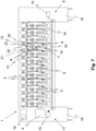
- FIG 7 shows a further embodiment of a textile machine 1 or a further variant of the method.
- the textile machine 1 also has two suction ducts 3 , with the spinning devices 10 being connected to a first suction duct 3 and the vacuum-consuming maintenance elements 8 being connected to a further suction duct 3 .
- a dirt belt 14 is also shown on the present textile machine 1, which removes dirt from the fiber material occurring at the work stations 2 and any superfluous fibers.
- the dirt transported on the dirt belt 14 is removed and disposed of at the two ends 9, 17 of the textile machine 1 a dirt belt suction device 15 is provided in each case.
- a single dirt belt suction device 15 is provided, which is then preferably arranged at the first end 9 of the textile machine 1 , which is opposite the second end 17 with the vacuum source 4 .
- At least one dirt belt suction device 15, which is preferably arranged at the first end 9, is opened in addition to the shut-off elements 6 of the respectively selected work stations 2.
Landscapes
- Engineering & Computer Science (AREA)
- Textile Engineering (AREA)
- Mechanical Engineering (AREA)
- Spinning Or Twisting Of Yarns (AREA)
Applications Claiming Priority (1)
| Application Number | Priority Date | Filing Date | Title |
|---|---|---|---|
| DE102020120312.8A DE102020120312A1 (de) | 2020-07-31 | 2020-07-31 | Verfahren zum Betreiben einer Textilmaschine sowie Textilmaschine |
Publications (1)
| Publication Number | Publication Date |
|---|---|
| EP3945149A1 true EP3945149A1 (fr) | 2022-02-02 |
Family
ID=79300608
Family Applications (1)
| Application Number | Title | Priority Date | Filing Date |
|---|---|---|---|
| EP21186211.5A Withdrawn EP3945149A1 (fr) | 2020-07-31 | 2021-07-16 | Procédé de fonctionnement d'une machine textile, ainsi que machine textile |
Country Status (3)
| Country | Link |
|---|---|
| EP (1) | EP3945149A1 (fr) |
| CN (1) | CN114059204A (fr) |
| DE (1) | DE102020120312A1 (fr) |
Families Citing this family (1)
| Publication number | Priority date | Publication date | Assignee | Title |
|---|---|---|---|---|
| CN115418760B (zh) * | 2022-10-11 | 2023-08-22 | 宿迁至诚纺织品股份有限公司 | 一种用于化纤纺纱的并条机 |
Citations (5)
| Publication number | Priority date | Publication date | Assignee | Title |
|---|---|---|---|---|
| GB886510A (en) * | 1958-07-25 | 1962-01-10 | Parks Cramer Co | A method of and installation for cleaning textile machines |
| DE4240233A1 (de) | 1992-11-30 | 1994-06-01 | Zinser Textilmaschinen Gmbh | Verfahren und Vorrichtung zum Betreiben einer Absauganlage |
| DE102016117302A1 (de) * | 2016-09-14 | 2018-03-15 | Maschinenfabrik Rieter Ag | Verfahren zum Betreiben einer Textilmaschine und Textilmaschine |
| DE102018112594A1 (de) * | 2018-05-25 | 2019-11-28 | Maschinenfabrik Rieter Ag | Verfahren zum Vorbereiten eines Garns zum Anspinnen an einer Rotorspinnvorrichtung einer Rotorspinnmaschine sowie Rotorspinnmaschine |
| EP3677711A1 (fr) * | 2018-10-22 | 2020-07-08 | Maschinenfabrik Rieter AG | Procédé de fonctionnement d'un métier à filer et métier à filer |
Family Cites Families (6)
| Publication number | Priority date | Publication date | Assignee | Title |
|---|---|---|---|---|
| US3986328A (en) | 1975-09-30 | 1976-10-19 | Parks-Cramer (Great Britain), Ltd. | Method and apparatus for pneumatically removing fiber and trash waste on open-end spinning machines |
| DE3611824C2 (de) | 1985-05-02 | 1998-07-02 | Rieter Ag Maschf | Verfahren und Anlage zum Betreiben von Fadenbruch- und/oder Luntenbruch-Absaugkanälen |
| CZ299685B6 (cs) * | 2001-09-05 | 2008-10-22 | Rieter Cz A.S. | Zpusob obnovování predení složkové príze na rotorovém doprádacím stroji a zarízení k provádení zpusobu |
| DE102016110147A1 (de) * | 2016-06-01 | 2017-12-07 | Rieter Ingolstadt Gmbh | Spinnmaschine mit einer Vielzahl von Arbeitsstellen und einer Absaugeinrichtung |
| DE102016119983A1 (de) * | 2016-10-20 | 2018-04-26 | Maschinenfabrik Rieter Ag | Pneumatisches Fadenspeicherorgan, Arbeitsstelle einer Textilmaschine mit einem Fadenspeicherorgan und Textilmaschine mit einer Vielzahl von Arbeitsstellen mit einem Fadenspeicherorgan |
| DE102018131571A1 (de) * | 2018-12-10 | 2020-06-10 | Saurer Spinning Solutions Gmbh & Co. Kg | Saugluftanlage |
-
2020
- 2020-07-31 DE DE102020120312.8A patent/DE102020120312A1/de not_active Withdrawn
-
2021
- 2021-07-16 EP EP21186211.5A patent/EP3945149A1/fr not_active Withdrawn
- 2021-07-21 CN CN202110826112.2A patent/CN114059204A/zh active Pending
Patent Citations (5)
| Publication number | Priority date | Publication date | Assignee | Title |
|---|---|---|---|---|
| GB886510A (en) * | 1958-07-25 | 1962-01-10 | Parks Cramer Co | A method of and installation for cleaning textile machines |
| DE4240233A1 (de) | 1992-11-30 | 1994-06-01 | Zinser Textilmaschinen Gmbh | Verfahren und Vorrichtung zum Betreiben einer Absauganlage |
| DE102016117302A1 (de) * | 2016-09-14 | 2018-03-15 | Maschinenfabrik Rieter Ag | Verfahren zum Betreiben einer Textilmaschine und Textilmaschine |
| DE102018112594A1 (de) * | 2018-05-25 | 2019-11-28 | Maschinenfabrik Rieter Ag | Verfahren zum Vorbereiten eines Garns zum Anspinnen an einer Rotorspinnvorrichtung einer Rotorspinnmaschine sowie Rotorspinnmaschine |
| EP3677711A1 (fr) * | 2018-10-22 | 2020-07-08 | Maschinenfabrik Rieter AG | Procédé de fonctionnement d'un métier à filer et métier à filer |
Also Published As
| Publication number | Publication date |
|---|---|
| CN114059204A (zh) | 2022-02-18 |
| DE102020120312A1 (de) | 2022-02-03 |
Similar Documents
| Publication | Publication Date | Title |
|---|---|---|
| EP0226582B1 (fr) | Procede et dispositif pour joindre les fils sur un systeme de filature a fibre liberee | |
| DE102011053813A1 (de) | Spinnmaschine sowie Verfahren zum Abführen eines Endabschnitts eines Garns an einer Spinnmaschine vor einem anschließenden Anspinnvorgang | |
| EP3312317B1 (fr) | Poste de travail d'une machine textile comprenant un dispositif de stockage de fil pneumatique et machine textile | |
| DE10353317B4 (de) | Verfahren und Vorrichtung zum Wiederherstellen eines zuvor unterbrochenen Spinnvorganges | |
| EP0162367B2 (fr) | Procédé et dispositif pour la préparation de l'extrémité de fil pour la remise en route d'une machine à bout libéré | |
| EP3945149A1 (fr) | Procédé de fonctionnement d'une machine textile, ainsi que machine textile | |
| EP3606855A1 (fr) | Dispositif et procédé d'aspiration, de stockage temporaire et d'évacuation d'un fil, ainsi que machine textile | |
| DE102019120980A1 (de) | Spinnmaschine mit einer Vielzahl nebeneinander angeordneter Arbeitsstellen und einer verfahrbaren Wartungseinrichtung mit einem pneumatischen Arbeitsorgan sowie Verfahren zum Versorgen des pneumatischen Arbeitsorgans mit Unterdruck | |
| EP3901336A1 (fr) | Métier à filer doté d'une pluralité de postes de travail les uns à côté des autres, ainsi que procédé de fonctionnement d'un métier à filer doté d'une pluralité de postes de travail les uns à côté des autres | |
| EP3839114B1 (fr) | Procédé d'agencement d'une bande de fibre sur une unité de filage d'un métier à filer | |
| DE2915788A1 (de) | Anspinnverfahren an einer offenend- rotorspinneinheit und vorrichtung zum durchfuehren dieses verfahrens | |
| DE102016117302A1 (de) | Verfahren zum Betreiben einer Textilmaschine und Textilmaschine | |
| DE10133152A1 (de) | Rotorspinnmaschine | |
| DE2023511C3 (de) | Offenendspinnmaschine | |
| EP2142690B1 (fr) | Dispositif de livraison d'un matériau fibreux étiré à un poste de travail d'une machine de traitement des matériaux fibreux | |
| EP4215655A1 (fr) | Procédé de fonctionnement d'un poste de filage d'un métier à filer à rotor et métier à filer à rotor | |
| DE102018112594A1 (de) | Verfahren zum Vorbereiten eines Garns zum Anspinnen an einer Rotorspinnvorrichtung einer Rotorspinnmaschine sowie Rotorspinnmaschine | |
| DE102018131571A1 (de) | Saugluftanlage | |
| DE102023001031A1 (de) | Verfahren zum Zuführen eines synthetischen Fadens | |
| DE102020131090A1 (de) | Verfahren zur Durchführung eines automatischen Kannenwechselvorgangs an einer Spinnstelle einer Spinnmaschine sowie Spinnmaschine und verfahrbarer Kannenwechsler | |
| DE202021102188U1 (de) | Spinn- oder Spulmaschine | |
| DE102020131089A1 (de) | Verfahren zur Durchführung eines automatischen Kannenwechselvorgangs an einer Spinnstelle einer Spinnmaschine sowie Spinnmaschine und verfahrbarer Kannenwechsler | |
| DE3416456C2 (de) | Verfahren und Vorrichtung zur Inbetriebnahme einer Friktionsspinnmaschine | |
| DE102020006536A1 (de) | Verfahren und Vorrichtung zum Wickeln eines Fadens zu einer Fadenspule | |
| DE102006018242A1 (de) | Luftdüsenspinnvorrichtung |
Legal Events
| Date | Code | Title | Description |
|---|---|---|---|
| PUAI | Public reference made under article 153(3) epc to a published international application that has entered the european phase |
Free format text: ORIGINAL CODE: 0009012 |
|
| STAA | Information on the status of an ep patent application or granted ep patent |
Free format text: STATUS: THE APPLICATION HAS BEEN PUBLISHED |
|
| AK | Designated contracting states |
Kind code of ref document: A1 Designated state(s): AL AT BE BG CH CY CZ DE DK EE ES FI FR GB GR HR HU IE IS IT LI LT LU LV MC MK MT NL NO PL PT RO RS SE SI SK SM TR |
|
| STAA | Information on the status of an ep patent application or granted ep patent |
Free format text: STATUS: REQUEST FOR EXAMINATION WAS MADE |
|
| 17P | Request for examination filed |
Effective date: 20220720 |
|
| RBV | Designated contracting states (corrected) |
Designated state(s): AL AT BE BG CH CY CZ DE DK EE ES FI FR GB GR HR HU IE IS IT LI LT LU LV MC MK MT NL NO PL PT RO RS SE SI SK SM TR |
|
| STAA | Information on the status of an ep patent application or granted ep patent |
Free format text: STATUS: EXAMINATION IS IN PROGRESS |
|
| 17Q | First examination report despatched |
Effective date: 20231128 |
|
| RAP3 | Party data changed (applicant data changed or rights of an application transferred) |
Owner name: RIETER AG |
|
| STAA | Information on the status of an ep patent application or granted ep patent |
Free format text: STATUS: THE APPLICATION IS DEEMED TO BE WITHDRAWN |
|
| 18D | Application deemed to be withdrawn |
Effective date: 20250627 |