EP3945156B1 - Innovatives elastisches lager für eisenbahnweichen, vorzugsweise vom selbstschmierenden typ - Google Patents
Innovatives elastisches lager für eisenbahnweichen, vorzugsweise vom selbstschmierenden typ Download PDFInfo
- Publication number
- EP3945156B1 EP3945156B1 EP20425030.2A EP20425030A EP3945156B1 EP 3945156 B1 EP3945156 B1 EP 3945156B1 EP 20425030 A EP20425030 A EP 20425030A EP 3945156 B1 EP3945156 B1 EP 3945156B1
- Authority
- EP
- European Patent Office
- Prior art keywords
- locking
- seat
- flexible element
- bearing
- wedge
- Prior art date
- Legal status (The legal status is an assumption and is not a legal conclusion. Google has not performed a legal analysis and makes no representation as to the accuracy of the status listed.)
- Active
Links
Images



Classifications
-
- E—FIXED CONSTRUCTIONS
- E01—CONSTRUCTION OF ROADS, RAILWAYS, OR BRIDGES
- E01B—PERMANENT WAY; PERMANENT-WAY TOOLS; MACHINES FOR MAKING RAILWAYS OF ALL KINDS
- E01B7/00—Switches; Crossings
- E01B7/02—Tongues; Associated constructions
Definitions
- the present invention relates to the technical field concerning railway technology, in particular the technical elements assigned to the implementation of a railway switch.
- the invention relates to an innovative bearing for needle sliding support, that is particularly simple and functional.
- the structural elements include a needle, a counter-needle and a metal support plate for these needles and counter-needles.
- the counter-needle is attached to this metal support which forms a supporting and sliding surface on which the needle moves and which can be moved away from and in the direction of the fixed counter-needle.
- the movement of the needle away from/in the direction of the counter-needle changes the path of the train by directing it in specific directions according to its position.
- the needle is moved through actuators.
- the metal plate can be structured in various more or less complex ways and can include lubrication systems to facilitate sliding of the needle, and rolling elements.
- bearing is used to refer to the assembly consisting of: metal support plate for attachment of the counter-needle, which also acts as sliding surface for the needle; devices for locking the counter-needle with respect to the above-mentioned metal plate; preferably potential devices to facilitate sliding of the needle on the metal support plate.
- Figures 1 to 3 for clarification purposes, constructively show an example of a commercially available Schwihag 60C28U brand bearing in complete kit form which includes the elastic attachment system for the counter-needle and the system that eliminates lubrication for the needle.
- Figure 4 shows an assembly sequence of this bearing assembly.
- figure 1 shows this metal plate 1 which forms a flat sliding surface 2 on which the needle 10 moves with respect to the counter-needle 20 (see also Figure 2 ).
- the counter-needle is attached to plate 1 and for this purpose plate 1 forms a receiving seat 3 for positioning of the counter-needle 20.
- the plate in this particular solution, includes rollers 30 ( Figure 2 shows only one) which facilitate sliding of the needle on surface 2 towards and away from the counter-needle, considerably reducing friction and therefore eliminating the need for lubrication.
- This spring as shown in the cross-section of figure 4 - phase A, has a hairpin shape (generally U-shaped or bow-shaped) and is inserted into a seat of the bearing so that one of its ends rests on the base of the counter-needle.
- a fulcrum is provided between the end of the spring which rests on the base of the counter needle and the opposite end of the spring which, as described immediately below, is raised with a special tool to set it into operation (i.e. in a load condition in which it exerts locking pressure on the counter-needle).
- a fulcrum is obtained as a tooth or a protrusion generally inside the seat.
- This solution describes a flexible locking element also in the form of a flexible metal sheet which is put in a load condition through the rotation of an eccentric pin.
- Figure 5 shows very well, in cross-section, the eccentric pin (PC) which, thanks to its eccentricity, raises the tail of the spring (CO) putting it in a load condition such that the front (PA) of the spring exerts a pressure force on the base (B) of the rail, locking it in position.
- PC eccentric pin
- This bearing (1) for railway switches includes:
- the construction solution is now very simple, includes few parts and is safe.
- the insertion of the wedge is a simple operation and its adequate conformation makes it very stable.
- the seat (5) may include at least one rotating fulcrum (5') inside it so that the flexing of the flexible element takes place around said rotating fulcrum.
- the rotating fulcrum can be in the form of a protrusion rising from the upper wall of said seat.
- said locking wedge (700) includes a safety area (705, 706) delimited by one or more walls arranged in such a way that, when the rear part (601) of the flexible element is inserted in said safety area (705, 706) following insertion of the locking wedge under said rear part (601) of the flexible element, said walls prevent the locking wedge from sliding towards the removal direction.
- said safety area (705, 706) may for example, be in the form of a seat dug in the thickness of the locking wedge on the part of the back which in use faces the overlying flexible element.
- said seat (705, 706) can for example, have a plan shape which follows the shape of the part of the flexible element which is intended to be inserted in said seat.
- said locking wedge may comprise a front portion having a bevel (701) which forms a chamfer to ease the insertion.
- the locking wedge can have a rear part (703) enlarged in such a way as to form a striking surface on which for example, a hammer may be used for insertion.
- said guide (720) can be delimited by two opposite facing walls spaced apart from each other.
- the said walls that delimit the said guide may include a first wall (721) which rises orthogonally from a surface of the said support (1) and a second wall which at least partially delimits the entrance to the seat (5).
- a protrusion (90) can be arranged to form an invitation to facilitate the arrangement of the front part (602) of the flexible element above the base of the rail.
- said locking wedge and said flexible element are configured in such a way that when the locking wedge is placed under the flexible element causing it to flex, the locking wedge is prevented from sliding in a direction of removal from underneath the flexible element.
- the flexible element can be in the form of a flexible sheet.
- a method for locking a rail (20) to a bearing (1) for railway switches is also described here, the method is as defined in independent claim 12.
- the loading operation includes raising with a lever (250) of the rear part (601) of the flexible element so as to inflect it, the subsequent insertion along the sliding guide of the locking wedge below the rear of the flexible element and the subsequent release of the lever (250) so that the flexible element is maintained in said flexed position through said locking wedge.
- the bearing is substantially the same as that presented of the prior art, so that like parts will be numbered with the same numbering.
- bearing means an assembly formed by:
- the support plate 1 is provided, generally metallic, which forms at the rear a flat sliding surface 2 on which the needle 10 can move (not shown in figures 9 and 6 ) with respect to the counter-needle 20 which is locked under a portion of the surface formed by the sliding surface 2.
- the counter-needle 20 is attached to the said plate 1 and, for this purpose, the plate 1 forms a receiving seat 3 for positioning of the counter-needle 20, which is then locked with the system described below.
- the part below the flat sliding surface forms a sliding channel 5 into which the locking spring is inserted.
- This spring is generally in the form of a flexible metal sheet, preferably steel, which is inserted in the above-mentioned channel.
- the channel as seen in section, has a rear and front opening in such a way that on one side it is possible to insert the sheet which protrudes partly both at the front, for locking, and at the rear for loading.
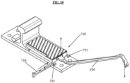
- a transversal guide 720 is therefore present, which guides the insertion of a wedge under the spring, avoiding the wedge going out of direction both during the insertion phase, to operate the locking that we will describe below, and during the release phase.
- This guide (also shown in Figure 10 ) is formed by two opposite facing walls.
- the width of the above-mentioned corridor, or guide is such as to allow the wedge to slide inside without too much play.
- the support structure 1, i.e. the plate 1, forms, as said, channel 5 under the sliding surface 2, exactly as in the prior art, and a rotating fulcrum 5' is provided inside said channel 5.
- It is in the form of a sheet of predetermined thickness, generally and preferably of steel.
- tail 601 which is raised by a special tool and it is the front part 602, preferably beveled, that is used to act on the back of the base of the rail to lock it.
- the front part 602 is beveled both on the back and on the belly of the sheet so that this front part 602 takes overall a pointed shape or, in section, a more or less triangular shape with the top cut.
- the bevel 602' on the back of the sheet is used during insertion to better overcome the protrusion 5' obtained in the insertion channel 5 of the bearing (see also figure 9 ) and prevent it from going against it and locking during insertion.
- the bevel on the belly 602" is used to form a chamfer that helps this tip to overcome the back of the base of the rail that it has to lock.
- component 90 is a beveled protuberance (a sort of springboard) that favors the sliding of bevel 602" in order to raise it and make it overcome the base of the rail on which it must rest.
- Figure 6 also shows, in section, the wall 721 which delimits the corridor for inserting the locking wedge 700 to the right.
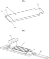
- Figure 7 shows an axonometric view of the locking wedge 700 which is used to tension the spring by locking it in position.
- the wedge provides a beveled front 701 which creates a chamfer which favors its positioning and subsequent sliding under the tail of the spring 600, as explained below.
- the locking wedge has a rear part 703 which forms an enlarged flat stop area 710 which can therefore be struck by a striking mass, for example, a hammer, in order to push the wedge to the locking position under spring 600.
- a striking mass for example, a hammer
- a seat (705, 706) is preferably obtained by removing material from this part of constant section.
- the seat follows the plan shape of a spring part (i.e. the plate) which goes into place within this seat, thus ensuring a snap-lock position.
- this seat has an overall T-shape and includes a portion 705 whose shape follows the lateral perimeter of the spring before the tail while it is on the narrow part 706 that the tail 601, which is narrower than the remaining part, is laid.
- an alternative solution may include one or more walls that rise from the back of the wedge in such a way that when the sheet passes over these walls, it fits elastically into the seat delimited by them and is thus prevented from sliding away, at least in the direction of the release motion of the wedge from the sheet.
- Such a locking area of the wedge under the sheet is not essential for the invention since the system would work equally well even without it.
- the system works as follows: As shown in Figure 9 (see direction of arrow), the elastic spring 600 is inserted inside the seat 5 of the support structure 1 where, on the opposite side, the rail 20 to be locked is arranged, as already described in the prior art.
- the spring chamfer 602 favors the correct positioning of the spring so that this bias 602 forms an inclined plane 602" which is positioned above the back of the rail base to be locked (basically, the sequence of figures 9 and 10 ) and which allows the fulcrum 5' located on the roof of the sliding seat 5 (back 602') to be overcome during insertion.
- the protrusion 5' forms a rotating fulcrum thus creating a lever which causes the sheet 600 to bend and therefore brings the front part of the spring 602 to press on the base of the rail placed under said front part.
- the protrusion although advantageous, is not essential since the upper edge of the seat at the rear opening (the part from where the tail protrudes) can act itself as a rotating fulcrum, while still allowing the plate to be tensioned.
- the locking wedge 700 comes into play, being positioned under the tail 601 as shown by the arrow in Figure 10 while the tail is kept raised via the crowbar 250.
- the lifting action with the crowbar may only be partial and sufficient to have the tip of the wedge enter under the tail 601, then making an insertion thanks to the help of a striking mass (for example, a hammer) that strikes the area 703 of the wedge.
- a striking mass for example, a hammer
- the guide delimited by the 721 and by the entrance wall to the channel 5 on the opposite side, helps to keep the wedge in its position during its translation under the tail up to the locking position, in which it snaps into place.
- the guide also avoids lateral movements, even after locking, thereby ensuring an important lateral locking.
- Snap-locking occurs in the case of a wedge with a back provided with a seat (705, 706), thanks to said seat (705, 706) made in the back of the wedge.
- the tail is raised by the greater thickness of the wedge until it intercepts and falls completely into this seat (a recess of one millimeter or less), therefore snapping into place.
- the tip 701 of the wedge is pushed by a striking mass along its path until the seat (705, 706) comes into the corresponding position under the tail so that a part of the spring, including a portion of the tail, fits correctly into the snap-in seat and locks into that seat.
- This seat is important, although not essential, as it avoids any accidental sliding, due possibly to vibration, which can cause a release of the wedge.
- insertion of the wedge may be carried out by totally lifting the tail with the crowbar so as to have a facilitated entry of the wedge that does not require strong impulses of the striking mass.
- the flexible element 600 has thus the function of a locking element and, accordingly, it can also be called as locking flexible element.
Landscapes
- Engineering & Computer Science (AREA)
- Mechanical Engineering (AREA)
- Architecture (AREA)
- Civil Engineering (AREA)
- Structural Engineering (AREA)
- Seats For Vehicles (AREA)
Claims (13)
- Lagerung (1) für Eisenbahnweichen, umfassend:- Einen Träger (2, 3), umfassend einen hinteren Teil (2) mit einem Sitz (5) und einen vorderen Teil (3), auf den eine zu verriegelnde Schiene (20) zu montieren ist;- Eine Verriegelungsbaugruppe (600, 700, 720), um der Schiene (20) zu ermöglichen, an dem vorderen Teil (3) angebracht zu werden, wobei die Verriegelungsbaugruppe ein flexibles Element (600) mit einem vorderen Teil (602) und einem hinteren Teil (601) umfasst, wobei das flexible Element (600) in den Sitz (5) einführbar ist, bis eine Verriegelungsposition erreicht ist, in der der vordere Teil (602) des flexiblen Elements dem vorderen Teil (3) des Trägers zugewandt ist, so dass das vordere Ende (602) des flexiblen Elements im Gebrauch einen Teil der Schiene überlappt, die sich in dem vorderen Teil (3) des Trägers befindet, um einen Verriegelungsdruck darauf auszuüben;
wobei es zudem umfasst: Eine Verriegelungskeil (700);- Eine Gleitführung (721), durch die der Verriegelungskeil (700) entlang eines Einführ-/Entnahmewegs geführt wird;- Wobei die Gleitführung in einer Position erhalten wird, sodass der Verriegelungskeil (700) unterhalb des hinteren Teils (601) des Verriegelungselements (600) in eine Rückhalteposition geführt wird, in der der Keil nach dem Gleiten des Verriegelungskeils (700) unter dem hinteren Teil (601) den hinteren Teil (601) anhebt, was eine Biegung des flexiblen Elements verursacht und somit einen Verriegelungsdruck erzeugt, den der vordere Teil (602) des flexiblen Elements auf den zu verriegelnden Teil der Schiene ausübt;- wobei die Länge des flexiblen Elements so ist, dass sein hinterer Teil (601) in der Verriegelungsposition zumindest teilweise aus dem Sitz (5) herausragt, wobei sich die Gleitführung (721) unterhalb des übersteigenden Teils positioniert, so dass der Verriegelungskeil außerhalb des Sitzes (5) auf den hinteren Teil wirkt;- Dadurch gekennzeichnet, dass die genannte (720) quer zur Längsrichtung der Gleitführung des Sitzes (5) in Bezug darauf angeordnet ist. - Lagerung (1) nach Anspruch 1, wobei der Verriegelungskeil (700) einen Sicherheitsbereich (705, 706) einschließt, der durch eine oder mehrere Wände begrenzt ist, die so angeordnet sind, dass, wenn der hintere Teil (601) des flexiblen Elements nach dem Einführen des Verriegelungskeils unter den hinteren Teil (601) des flexiblen Elements in den Sicherheitsbereich (705, 7O6) eingeführt wird, die Wände verhindern, dass der Verriegelungskeil in Richtung der Entnahmerichtung gleitet.
- Lagerung (1) nach Anspruch 2, wobei der Sicherheitsbereich (705, 706) in Form eines Sitzes vorliegt, der in die Dicke des Verriegelungskeils auf dem Teil der Rückseite gegraben ist, der im Gebrauch dem darüber liegenden flexiblen Element zugewandt ist.
- Lagerung (1) nach Anspruch 3, wobei der Sitz (705, 706) eine Grundrissform aufweist, die der Grundrissform des Teils des flexiblen Elements folgt, der dazu bestimmt ist, in den Sitz zu passen.
- Lagerung (1) nach einem oder mehreren der vorhergehenden Ansprüche, wobei der Verriegelungskeil einen vorderen Abschnitt mit einer Verjüngung (701) einschließt, die eine Vorspannung zur Einführung bildet.
- Lagerung nach einem oder mehreren der vorhergehenden Ansprüche, wobei der Verriegelungskeil einen hinteren Teil (703) aufweist, der sich derart erstreckt, dass er eine Anschlagfläche bildet.
- Lagerung (1) nach einem oder mehreren der vorhergehenden Ansprüche, wobei die Gleitführung (720) durch zwei einander gegenüberliegende zugewandte Wände begrenzt ist, die voneinander beabstandet sind.
- Lagerung (1) nach Anspruch 7, wobei die Wände, die die Gleitführung begrenzen, eine erste Wand (721), die sich orthogonal von einer Oberfläche des Trägers (1) erhebt, und eine zweite Wand einschließen, die den Eingang zum Sitz (5) zumindest teilweise begrenzt.
- Lagerung (1) nach einem oder mehreren der vorhergehenden Ansprüche, wobei sich innerhalb des Sitzes (5) ein Vorsprung (90) befindet, der eine Vorspannung bildet, um die Anordnung des vorderen Teils (602) des flexiblen Elements oberhalb der Basis der Schiene zu erleichtern.
- Lagerung nach einem oder mehreren der vorhergehenden Ansprüche, wobei das flexible Element eine flexible Platte ist.
- Lagerung nach einem oder mehreren der vorhergehenden Ansprüche, wobei sich der Sitz (5) in Längsrichtung entwickelt und eine vordere Öffnung und eine hintere Öffnung einschließt, so dass das flexible Element hinten entlang des Sitzes eingeführt werden kann, bis eines seiner Enden aus der vorderen Öffnung herausragt, wodurch die zu verriegelnde Schiene überlappt wird.
- Verfahren zum Verriegeln einer Schiene (20) an einer Lagerung (1) für Eisenbahnweichen, wobei das Verfahren die folgenden Schritte umfasst:- Anordnen der Schiene in einem Sitz (3) eines Trägers (2, 3), der Teil der Lagerung ist;- Einführen eines flexiblen Elements (600) in einen Sitz (5) des Trägers (2, 3), bis eine Position erreicht wird, in der der vordere Teil (602) des flexiblen Elements über einem Teil der Basis der im Sitz (3) angeordneten Schiene positioniert wird;- Laden des flexiblen Elements, sodass der vordere Teil (602) einen Verriegelungsdruck auf die Basis der Schiene ausübt, mit der er in Kontakt steht, indem er sie in seiner Position verriegelt;- und wobei der Ladevorgang das Einsetzen eines Verriegelungskeils (700) einschließt, der veranlasst wird, entlang einer Gleitführung (721) zu gleiten, bis der Verriegelungskeil (700) unter einen Teil (601) des Verriegelungselements (600) gelangt, sodass ein Teil davon angehoben gehalten wird, wodurch eine Biegung des flexiblen Elements verursacht wird, die den Verriegelungsdruck erzeugt, wobei die Länge des flexiblen Elements so bemessen ist, dass in der Verriegelungsposition sein hinterer Teil (601) zumindest teilweise aus dem Sitz (5) herausragt, wobei die Gleitführung (721) sich unterhalb des übersteigenden Teils positioniert, so dass der Verriegelungskeil auf den hinteren Teil außerhalb des Sitzes (5) wirktdadurch gekennzeichnet, dass die Gleitführung (720) quer zur Längsrichtung des Sitzes (5) angeordnet ist.
- Verfahren nach Anspruch 12, wobei der Ladevorgang das Anheben des hinteren Teils (601) des flexiblen Elements mit einem Hebel (250), um ihn zu biegen, das anschließende Einführen des Verriegelungskeils entlang der Gleitführung unter der Rückseite des flexiblen Elements und das anschließende Lösen des Hebels (250), so dass das flexible Element durch den Verriegelungskeil in der gebeugten Position gehalten wird, einschließt.
Priority Applications (1)
| Application Number | Priority Date | Filing Date | Title |
|---|---|---|---|
| EP20425030.2A EP3945156B1 (de) | 2020-07-31 | 2020-07-31 | Innovatives elastisches lager für eisenbahnweichen, vorzugsweise vom selbstschmierenden typ |
Applications Claiming Priority (1)
| Application Number | Priority Date | Filing Date | Title |
|---|---|---|---|
| EP20425030.2A EP3945156B1 (de) | 2020-07-31 | 2020-07-31 | Innovatives elastisches lager für eisenbahnweichen, vorzugsweise vom selbstschmierenden typ |
Publications (3)
| Publication Number | Publication Date |
|---|---|
| EP3945156A1 EP3945156A1 (de) | 2022-02-02 |
| EP3945156C0 EP3945156C0 (de) | 2023-11-29 |
| EP3945156B1 true EP3945156B1 (de) | 2023-11-29 |
Family
ID=72615806
Family Applications (1)
| Application Number | Title | Priority Date | Filing Date |
|---|---|---|---|
| EP20425030.2A Active EP3945156B1 (de) | 2020-07-31 | 2020-07-31 | Innovatives elastisches lager für eisenbahnweichen, vorzugsweise vom selbstschmierenden typ |
Country Status (1)
| Country | Link |
|---|---|
| EP (1) | EP3945156B1 (de) |
Family Cites Families (4)
| Publication number | Priority date | Publication date | Assignee | Title |
|---|---|---|---|---|
| AT389721B (de) * | 1988-05-20 | 1990-01-25 | Voest Alpine Maschinenbau | Vorrichtung zum befestigen von backenschienen in weichen |
| AT402747B (de) * | 1995-06-09 | 1997-08-25 | Vae Ag | Vorrichtung zum befestigen von backenschienen in weichen |
| JP6706842B2 (ja) * | 2016-07-06 | 2020-06-10 | 東日本旅客鉄道株式会社 | レール締結装置 |
| EP3473519A1 (de) | 2017-10-23 | 2019-04-24 | D.R. Ferroviaria Italia S.r.l. | Innovatives elastisches lager für schaltpunkte, vorzugsweise selbstschmierende lager |
-
2020
- 2020-07-31 EP EP20425030.2A patent/EP3945156B1/de active Active
Also Published As
| Publication number | Publication date |
|---|---|
| EP3945156C0 (de) | 2023-11-29 |
| EP3945156A1 (de) | 2022-02-02 |
Similar Documents
| Publication | Publication Date | Title |
|---|---|---|
| US5247789A (en) | Plastic chain comprising mountable guide means and/or mountable means | |
| US6443723B1 (en) | Slide retainer for an injection mold | |
| US20050235700A1 (en) | System component having a braking spring | |
| KR100844196B1 (ko) | 편물기의 편물바늘로서의 편물부재 | |
| US20070147713A1 (en) | Linear Guide Apparatus | |
| EP2049367A1 (de) | Vorrichtung zum halten einer kamera an einem träger | |
| US11193242B2 (en) | Railway tie plate retention devices and methods to facilitate railway tie replacement | |
| SE505885C2 (sv) | Cylinderlås-nyckelkombination, nyckel, nyckelämne och lås ingående i kombinationen | |
| US11470966B2 (en) | Guiding apparatus | |
| EP3945156A1 (de) | Innovatives elastisches lager für eisenbahnweichen, vorzugsweise vom selbstschmierenden typ | |
| KR100852230B1 (ko) | 편물기의 바 | |
| US7798583B2 (en) | Detent pin bearing retainer lock for a drawer slide | |
| US11052827B2 (en) | Car cargo space cover | |
| KR100476496B1 (ko) | 시스템 부품 | |
| KR100858727B1 (ko) | 프로그레시브금형의 사이드커팅장치 | |
| US6151929A (en) | Device for fastening active components to the bar of a wrap knitting machine and accompanying tool for removing and installing the active components | |
| AU611294B2 (en) | Arrangement in insert holders | |
| US6574995B2 (en) | Latch needle comprising a relieved latch shank | |
| EP0369582A2 (de) | Schmiervorrichtung für die Aufhängungslagerung eines Fahrmotors | |
| US20240167301A1 (en) | Coupling element, locking system and furniture | |
| US6793439B1 (en) | Securing device for a drainage channel | |
| KR20030027782A (ko) | 시스템 요소 | |
| EP0150334A2 (de) | Führungsvorrichtung für Befestigungselemente, und Eintriebgerät mit solcher Vorrichtung | |
| EP3869048A1 (de) | Profilbefestigungsmittel | |
| CN113883190B (zh) | 轨道车辆的闸瓦以及闸瓦装置 |
Legal Events
| Date | Code | Title | Description |
|---|---|---|---|
| PUAI | Public reference made under article 153(3) epc to a published international application that has entered the european phase |
Free format text: ORIGINAL CODE: 0009012 |
|
| STAA | Information on the status of an ep patent application or granted ep patent |
Free format text: STATUS: THE APPLICATION HAS BEEN PUBLISHED |
|
| AK | Designated contracting states |
Kind code of ref document: A1 Designated state(s): AL AT BE BG CH CY CZ DE DK EE ES FI FR GB GR HR HU IE IS IT LI LT LU LV MC MK MT NL NO PL PT RO RS SE SI SK SM TR |
|
| STAA | Information on the status of an ep patent application or granted ep patent |
Free format text: STATUS: REQUEST FOR EXAMINATION WAS MADE |
|
| 17P | Request for examination filed |
Effective date: 20220712 |
|
| RBV | Designated contracting states (corrected) |
Designated state(s): AL AT BE BG CH CY CZ DE DK EE ES FI FR GB GR HR HU IE IS IT LI LT LU LV MC MK MT NL NO PL PT RO RS SE SI SK SM TR |
|
| P01 | Opt-out of the competence of the unified patent court (upc) registered |
Effective date: 20230418 |
|
| GRAP | Despatch of communication of intention to grant a patent |
Free format text: ORIGINAL CODE: EPIDOSNIGR1 |
|
| STAA | Information on the status of an ep patent application or granted ep patent |
Free format text: STATUS: GRANT OF PATENT IS INTENDED |
|
| RIC1 | Information provided on ipc code assigned before grant |
Ipc: E01B 7/02 20060101AFI20230531BHEP |
|
| INTG | Intention to grant announced |
Effective date: 20230629 |
|
| P02 | Opt-out of the competence of the unified patent court (upc) changed |
Effective date: 20230621 |
|
| GRAS | Grant fee paid |
Free format text: ORIGINAL CODE: EPIDOSNIGR3 |
|
| GRAA | (expected) grant |
Free format text: ORIGINAL CODE: 0009210 |
|
| STAA | Information on the status of an ep patent application or granted ep patent |
Free format text: STATUS: THE PATENT HAS BEEN GRANTED |
|
| AK | Designated contracting states |
Kind code of ref document: B1 Designated state(s): AL AT BE BG CH CY CZ DE DK EE ES FI FR GB GR HR HU IE IS IT LI LT LU LV MC MK MT NL NO PL PT RO RS SE SI SK SM TR |
|
| REG | Reference to a national code |
Ref country code: GB Ref legal event code: FG4D |
|
| REG | Reference to a national code |
Ref country code: CH Ref legal event code: EP |
|
| REG | Reference to a national code |
Ref country code: DE Ref legal event code: R096 Ref document number: 602020021840 Country of ref document: DE |
|
| REG | Reference to a national code |
Ref country code: IE Ref legal event code: FG4D |
|
| U01 | Request for unitary effect filed |
Effective date: 20231213 |
|
| U07 | Unitary effect registered |
Designated state(s): AT BE BG DE DK EE FI FR IT LT LU LV MT NL PT SE SI Effective date: 20231219 |
|
| P04 | Withdrawal of opt-out of the competence of the unified patent court (upc) registered |
Effective date: 20231215 |
|
| PG25 | Lapsed in a contracting state [announced via postgrant information from national office to epo] |
Ref country code: GR Free format text: LAPSE BECAUSE OF FAILURE TO SUBMIT A TRANSLATION OF THE DESCRIPTION OR TO PAY THE FEE WITHIN THE PRESCRIBED TIME-LIMIT Effective date: 20240301 |
|
| PG25 | Lapsed in a contracting state [announced via postgrant information from national office to epo] |
Ref country code: IS Free format text: LAPSE BECAUSE OF FAILURE TO SUBMIT A TRANSLATION OF THE DESCRIPTION OR TO PAY THE FEE WITHIN THE PRESCRIBED TIME-LIMIT Effective date: 20240329 |
|
| PG25 | Lapsed in a contracting state [announced via postgrant information from national office to epo] |
Ref country code: ES Free format text: LAPSE BECAUSE OF FAILURE TO SUBMIT A TRANSLATION OF THE DESCRIPTION OR TO PAY THE FEE WITHIN THE PRESCRIBED TIME-LIMIT Effective date: 20231129 |
|
| PG25 | Lapsed in a contracting state [announced via postgrant information from national office to epo] |
Ref country code: IS Free format text: LAPSE BECAUSE OF FAILURE TO SUBMIT A TRANSLATION OF THE DESCRIPTION OR TO PAY THE FEE WITHIN THE PRESCRIBED TIME-LIMIT Effective date: 20240329 Ref country code: GR Free format text: LAPSE BECAUSE OF FAILURE TO SUBMIT A TRANSLATION OF THE DESCRIPTION OR TO PAY THE FEE WITHIN THE PRESCRIBED TIME-LIMIT Effective date: 20240301 Ref country code: ES Free format text: LAPSE BECAUSE OF FAILURE TO SUBMIT A TRANSLATION OF THE DESCRIPTION OR TO PAY THE FEE WITHIN THE PRESCRIBED TIME-LIMIT Effective date: 20231129 |
|
| PG25 | Lapsed in a contracting state [announced via postgrant information from national office to epo] |
Ref country code: RS Free format text: LAPSE BECAUSE OF FAILURE TO SUBMIT A TRANSLATION OF THE DESCRIPTION OR TO PAY THE FEE WITHIN THE PRESCRIBED TIME-LIMIT Effective date: 20231129 Ref country code: PL Free format text: LAPSE BECAUSE OF FAILURE TO SUBMIT A TRANSLATION OF THE DESCRIPTION OR TO PAY THE FEE WITHIN THE PRESCRIBED TIME-LIMIT Effective date: 20231129 Ref country code: NO Free format text: LAPSE BECAUSE OF FAILURE TO SUBMIT A TRANSLATION OF THE DESCRIPTION OR TO PAY THE FEE WITHIN THE PRESCRIBED TIME-LIMIT Effective date: 20240229 Ref country code: HR Free format text: LAPSE BECAUSE OF FAILURE TO SUBMIT A TRANSLATION OF THE DESCRIPTION OR TO PAY THE FEE WITHIN THE PRESCRIBED TIME-LIMIT Effective date: 20231129 |
|
| U20 | Renewal fee for the european patent with unitary effect paid |
Year of fee payment: 5 Effective date: 20240607 |
|
| PG25 | Lapsed in a contracting state [announced via postgrant information from national office to epo] |
Ref country code: CZ Free format text: LAPSE BECAUSE OF FAILURE TO SUBMIT A TRANSLATION OF THE DESCRIPTION OR TO PAY THE FEE WITHIN THE PRESCRIBED TIME-LIMIT Effective date: 20231129 |
|
| PG25 | Lapsed in a contracting state [announced via postgrant information from national office to epo] |
Ref country code: SK Free format text: LAPSE BECAUSE OF FAILURE TO SUBMIT A TRANSLATION OF THE DESCRIPTION OR TO PAY THE FEE WITHIN THE PRESCRIBED TIME-LIMIT Effective date: 20231129 |
|
| PG25 | Lapsed in a contracting state [announced via postgrant information from national office to epo] |
Ref country code: SM Free format text: LAPSE BECAUSE OF FAILURE TO SUBMIT A TRANSLATION OF THE DESCRIPTION OR TO PAY THE FEE WITHIN THE PRESCRIBED TIME-LIMIT Effective date: 20231129 Ref country code: SK Free format text: LAPSE BECAUSE OF FAILURE TO SUBMIT A TRANSLATION OF THE DESCRIPTION OR TO PAY THE FEE WITHIN THE PRESCRIBED TIME-LIMIT Effective date: 20231129 Ref country code: RO Free format text: LAPSE BECAUSE OF FAILURE TO SUBMIT A TRANSLATION OF THE DESCRIPTION OR TO PAY THE FEE WITHIN THE PRESCRIBED TIME-LIMIT Effective date: 20231129 Ref country code: CZ Free format text: LAPSE BECAUSE OF FAILURE TO SUBMIT A TRANSLATION OF THE DESCRIPTION OR TO PAY THE FEE WITHIN THE PRESCRIBED TIME-LIMIT Effective date: 20231129 |
|
| REG | Reference to a national code |
Ref country code: DE Ref legal event code: R097 Ref document number: 602020021840 Country of ref document: DE |
|
| PLBE | No opposition filed within time limit |
Free format text: ORIGINAL CODE: 0009261 |
|
| STAA | Information on the status of an ep patent application or granted ep patent |
Free format text: STATUS: NO OPPOSITION FILED WITHIN TIME LIMIT |
|
| 26N | No opposition filed |
Effective date: 20240830 |
|
| P05 | Withdrawal of opt-out of the competence of the unified patent court (upc) changed |
Free format text: CASE NUMBER: APP_594990/2023 Effective date: 20231219 |
|
| PG25 | Lapsed in a contracting state [announced via postgrant information from national office to epo] |
Ref country code: MC Free format text: LAPSE BECAUSE OF FAILURE TO SUBMIT A TRANSLATION OF THE DESCRIPTION OR TO PAY THE FEE WITHIN THE PRESCRIBED TIME-LIMIT Effective date: 20231129 |
|
| REG | Reference to a national code |
Ref country code: CH Ref legal event code: PL |
|
| GBPC | Gb: european patent ceased through non-payment of renewal fee |
Effective date: 20240731 |
|
| PG25 | Lapsed in a contracting state [announced via postgrant information from national office to epo] |
Ref country code: CH Free format text: LAPSE BECAUSE OF NON-PAYMENT OF DUE FEES Effective date: 20240731 |
|
| PG25 | Lapsed in a contracting state [announced via postgrant information from national office to epo] |
Ref country code: GB Free format text: LAPSE BECAUSE OF NON-PAYMENT OF DUE FEES Effective date: 20240731 |
|
| PG25 | Lapsed in a contracting state [announced via postgrant information from national office to epo] |
Ref country code: IE Free format text: LAPSE BECAUSE OF NON-PAYMENT OF DUE FEES Effective date: 20240731 |
|
| U20 | Renewal fee for the european patent with unitary effect paid |
Year of fee payment: 6 Effective date: 20250707 |
|
| PG25 | Lapsed in a contracting state [announced via postgrant information from national office to epo] |
Ref country code: CY Free format text: LAPSE BECAUSE OF FAILURE TO SUBMIT A TRANSLATION OF THE DESCRIPTION OR TO PAY THE FEE WITHIN THE PRESCRIBED TIME-LIMIT; INVALID AB INITIO Effective date: 20200731 |
|
| PG25 | Lapsed in a contracting state [announced via postgrant information from national office to epo] |
Ref country code: HU Free format text: LAPSE BECAUSE OF FAILURE TO SUBMIT A TRANSLATION OF THE DESCRIPTION OR TO PAY THE FEE WITHIN THE PRESCRIBED TIME-LIMIT; INVALID AB INITIO Effective date: 20200731 |