EP3945169A1 - Bande d'étanchéité - Google Patents
Bande d'étanchéité Download PDFInfo
- Publication number
- EP3945169A1 EP3945169A1 EP21186972.2A EP21186972A EP3945169A1 EP 3945169 A1 EP3945169 A1 EP 3945169A1 EP 21186972 A EP21186972 A EP 21186972A EP 3945169 A1 EP3945169 A1 EP 3945169A1
- Authority
- EP
- European Patent Office
- Prior art keywords
- sealing
- bath
- tray support
- shower tray
- drain
- Prior art date
- Legal status (The legal status is an assumption and is not a legal conclusion. Google has not performed a legal analysis and makes no representation as to the accuracy of the status listed.)
- Pending
Links
Images


Classifications
-
- E—FIXED CONSTRUCTIONS
- E03—WATER SUPPLY; SEWERAGE
- E03F—SEWERS; CESSPOOLS
- E03F5/00—Sewerage structures
- E03F5/04—Gullies inlets, road sinks, floor drains with or without odour seals or sediment traps
- E03F5/0407—Floor drains for indoor use
- E03F5/0409—Devices for preventing seepage around the floor drain
-
- A—HUMAN NECESSITIES
- A47—FURNITURE; DOMESTIC ARTICLES OR APPLIANCES; COFFEE MILLS; SPICE MILLS; SUCTION CLEANERS IN GENERAL
- A47K—SANITARY EQUIPMENT; ACCESSORIES THEREFOR, e.g. TOILET ACCESSORIES
- A47K3/00—Baths; Showers; Appurtenances therefor
- A47K3/008—Sealing between wall and bathtub or shower tray
Definitions
- the invention relates to a sealing membrane for use in sealingly receiving a bath or shower tray support, a bath or shower tray support set and a method for installing a bath or shower tray support.
- Bathtub or shower tray supports have established themselves as substructure elements for a bathtub or shower area. Bathtubs or shower trays are often mounted on these bath or shower tray supports; Especially with floor-level shower areas, however, only tiles or another surface covering are often applied.
- the object of the present invention is, independently of the given technical solutions, to provide measures that further reduce the risk of water penetrating into the building structure.
- a key consideration of the present invention is that a sealing sheet is proposed for use in sealingly receiving a bath or shower tray support, with the sealing sheet being designed as a film element that is larger by lateral projections than the surface dimensions of the bath or shower tray support and has a minimal area of 0.4 m 2 and a maximum area of 6 m 2 and is provided with at least one drain duct, wherein the drain duct comprises a sealing device or is designed and intended to interact with a sealing device, in particular for the fluid-tight connection of the sealing membrane to a drain pipe or drain pipe section.
- the bath or shower tray support set according to the invention also consists of a bath or shower tray support and a sealing membrane for sealingly receiving a bath or shower tray support, the sealing membrane being designed as a film element that is larger by the side overhangs than the surface dimensions of the bath or shower tray support and a has a minimum area of 0.4 m 2 and a maximum area of 6 m 2 and is provided with at least one drainage duct, the drainage duct comprising a sealing device or being designed and intended to interact with a sealing device, in particular for the fluid-tight connection of the sealing membrane to a drainpipe or drainpipe section.
- the sealing device comprises elements or structures for reversible sealing to the drain pipe and is thus designed and intended for reversible sealing with respect to the sealing pipe.
- the reversible seal that is preferably provided has the advantage that the fitter when installing the bath or shower tray support can again correct incorrectly manufactured connections of the drain pipe or drain pipe section and thus the seal between drain pipe or drain pipe section and sealing device can also be solved again or re-established.
- the sealing device can include substances that react with certain substances, which then create a permanent seal between the sealing device and the drain pipe or drain pipe section.
- the sealing device comprises a sealing element made from an expandable material and having a central opening for the discharge pipe or the discharge pipe section to be pushed through.
- a sealing device is particularly easy and reliable to produce and at the same time such a sealing device proves to be particularly error-prone with regard to assembly.
- the sealing element can comprise a circular ring disk made of expandable material or be formed from such a circular ring disk.
- the sealing element can have a basic shape in the shape of a cone envelope, i.e. a funnel shape, so that a preferred direction is specified with regard to pushing the drain pipe or the drain pipe section on and in and pulling it back is made more difficult.
- the sealing element comprises an elastomer material or is formed from such.
- the drain lead-through can be designed as a plate-shaped body with a through-opening for a drain pipe or a drain pipe section and thus define a drain lead-through plate, designed and intended to serve as a clamping system for a sealing device inserted between the drain pipe and drain lead-through plate.
- the sealing device can be designed as a sealing sleeve, with a circumferential first sealing bead and a second sealing bead arranged spatially separate therefrom, with a spacing being provided between the first sealing bead and the second sealing bead, which is preferably designed to be slightly smaller than the thickness of the drain duct , so that there is a clamping seal between the drain penetration plate and the sealing sleeve.
- the foil element of the sealing sheet can be frictionally connected to the drain lead-through plate, in particular clamped via the sealing sleeve, or also materially bonded, for example by means of an adhesive, to the drain lead-through plate in a sealing manner.
- both the film element and the sealing plate are formed from a corresponding material, in particular from weldable plastic materials, to weld the film element and the drain lead-through plate to one another in a fluid-tight manner.
- the foil element comprises a non-woven fabric or is formed from such a fabric.
- the film element Since the material properties and requirements between the sealing element and the rest of the film element differ significantly, it may appear sensible if the film element is provided with a connection device for fluid-tight integration of the sealing element in the rest of the film element forming an assembly base.
- connection device itself can comprise a film or be designed as a film.
- one or more leak detection devices for detecting existing liquid or moisture to detect leaks can be provided on or in the film element of the sealing membrane, in particular also in the area of the drain duct .
- a leakage detection device can include one or more sensors that are able to detect liquid or moisture.
- these sensors can also be operatively connected to corresponding signal processing devices or signal output devices in order to detect the presence of liquid or moisture and to output a corresponding signal.
- Corresponding leakage detection devices can also generally be provided in the area between the bath or shower tray support and the sealing membrane, in particular also on the bath or shower tray support itself and/or in or on the sealing membrane and/or on or within the drain duct, whereby both are conceivable to provide only one leak detection device as well as several leakage detection devices.
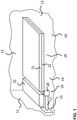
- FIG 1 a schematic basic view of the installation situation of a shower tray support 25 on a sealing strip 18 according to the invention is illustrated in a schematic sectional view.
- the shower tray support 25 is designed here in two parts with an upper part 21 and a lower part 22 .
- a drainage system 19 with a siphon 20 is provided in or on the lower part 22 .
- the siphon 20 is followed by a drain pipe 17, which is guided through the sealing strip 18 via a drain duct 15, which will be explained in more detail below, and opens into a wall-side drain pipe (not shown).
- the shower tray support 25 is enclosed from its underside by the sealing strip 18 , which has lateral overhangs 11 to 14 projecting in relation to the shower tray support, so that a trough-shaped receiving pocket is formed by the sealing strip 18 .
- escaping water is absorbed by the receiving pocket formed by the sealing strip 18 without penetrating into the building. Water damage to the building can be avoided in this way.
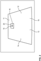
- FIG 2 1 is an embodiment of a sealing membrane 18 according to the invention.
- the sealing membrane 18 comprises a uniformly designed main area 26 and a—already mentioned—drainage passage 15 which has a sealing device 16 in the form of a sealing collar.
- the sealing sleeve is with the present one Embodiment designed as a circular disc, the inner diameter being dimensioned such that a drain pipe 17 or a drain pipe section can be performed sealingly through the sealing collar.
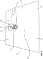
- figure 3 is the embodiment according to figure 2 illustrated with the drain pipe 17 pushed through.
- a siphon 20 is already connected to the drain pipe 17 as part of the drain system 19 on the shower tray side.
- FIG 4 1 is a sectional view of the passage of a drain pipe 17 through a drain duct 15 comprising a sealing device 16 in a sealing membrane 18 according to an embodiment of the present invention.
- a connection device 23 for connecting the sealing device 16 to the main part of the sealing membrane 18 is illustrated within the sealing membrane 18 .
- the sealing device 16 embodied here as a sealing collar is connected in a fluid-tight manner within the connection device 23 .
- the drain pipe 17 is pushed through the sealing collar 16, which can have the shape of a circular disc, for example.
- FIG 5 Another embodiment of the sealing sheet 18 is shown schematically in plan view. Also indicated here is the bearing surface 24 covered by the underside of the shower tray support 25 in the installed position, on which the shower tray support 25 comes to rest in the installed state.
- the areas provided outside of the support surface 24 form the lateral projections 11 to 14, which are folded upwards when the shower tray support is installed and form the pocket-like receptacle for receiving any water that may escape from leaks.
- the folded-up lateral projections 11 to 14 can at the same time be connected flat to a wall on the wall side, in order to also form a wall-side seal.
- Lateral projections 13, 14, which are not assigned directly to any wall, can be laid or shortened underneath tiles that are attached to the side of the tub support.
- one or more leakage detection devices can be installed on the sealing sheet 18 and/or in the area of the drain duct 15 32 can be provided, each designed as an electronic sensor and having a self-sufficient power supply, for example in the form of a battery, as well as communication devices, in order to communicate in particular wirelessly with a central signal processing device and a signal, such as detected moisture or the presence of a liquid as output signal.
- sealing membrane 18 which interacts with a sealing device, illustrated schematically in a sectional view.
- the sealing membrane 18 is also used here for sealingly receiving a bath or shower tray support and is designed as a film element that is larger by lateral projections 11-14 compared to the surface dimensions of the bath or shower tray support, with only part of the sealing membrane 18 being shown here.
- the sealing strip 18 has a drainage passage 15 which interacts with a sealing device 16 .
- the sealing device 16 is designed here in the form of a sealing sleeve 27, which can be designed, for example, as a rotationally symmetrical body with a cylindrical through-opening and consists, for example, of an elastomeric material.
- the sealing sleeve 27 has a first sealing bead 28, which extends in the circumferential direction, and a second sealing bead 29, which also extends spatially from the first sealing bead 28 in the circumferential direction of the sealing sleeve 27.
- a spacing 30 is defined between the first sealing bead 28 and the second sealing bead 29 and is dimensioned such that a peripheral edge section 33 of a drain lead-through plate 31 can be accommodated therein.
- the sealing strip 18 is materially connected to the drain lead-through plate 31 in a fluid-tight manner, for example glued.
- both the drainage lead-through plate 31 and the sealing strip 18 are made of appropriate materials, to produce a fluid-tight welded connection between the two parts.
- the sealing strip is only held in a clamped manner on the drain lead-through plate 31 and thus a fluid-tight connection between the drain lead-through plate 31 and Waterproofing membrane 18 is given.
- the drain lead-through plate 31 is held in a clamped manner in the sealing sleeve 27 in that the spacing 30 between the first sealing bead 28 and the second sealing bead 29 is preferably dimensioned slightly smaller than the thickness of the drain lead-through plate 31, so that both the first sealing bead 28 and the second sealing bead 29 have a certain , exert a predetermined clamping force on the drain penetration plate 31 and the sealing membrane 18 .
Landscapes
- Health & Medical Sciences (AREA)
- Public Health (AREA)
- Life Sciences & Earth Sciences (AREA)
- Engineering & Computer Science (AREA)
- Hydrology & Water Resources (AREA)
- Water Supply & Treatment (AREA)
- Epidemiology (AREA)
- General Health & Medical Sciences (AREA)
- Sink And Installation For Waste Water (AREA)
Applications Claiming Priority (1)
| Application Number | Priority Date | Filing Date | Title |
|---|---|---|---|
| DE102020120106.0A DE102020120106A1 (de) | 2020-07-30 | 2020-07-30 | Abdichtungsbahn |
Publications (1)
| Publication Number | Publication Date |
|---|---|
| EP3945169A1 true EP3945169A1 (fr) | 2022-02-02 |
Family
ID=77021158
Family Applications (1)
| Application Number | Title | Priority Date | Filing Date |
|---|---|---|---|
| EP21186972.2A Pending EP3945169A1 (fr) | 2020-07-30 | 2021-07-21 | Bande d'étanchéité |
Country Status (2)
| Country | Link |
|---|---|
| EP (1) | EP3945169A1 (fr) |
| DE (1) | DE102020120106A1 (fr) |
Cited By (2)
| Publication number | Priority date | Publication date | Assignee | Title |
|---|---|---|---|---|
| IT202200025290A1 (it) * | 2022-12-09 | 2024-06-09 | Alessandro Buccolieri | Sifone di scarico a pavimento, piletta di scarico a pavimento per piatto doccia o vasca da bagno |
| IT202200025284A1 (it) * | 2022-12-09 | 2024-06-09 | Alessandro Buccolieri | Sifone di scarico a pavimento, piletta di scarico a pavimento per piatto doccia o vasca da bagno |
Citations (4)
| Publication number | Priority date | Publication date | Assignee | Title |
|---|---|---|---|---|
| EP0240764A1 (fr) * | 1986-04-09 | 1987-10-14 | PCI Polychemie Augsburg GmbH | Elément d'étanchéité pour l'étanchéification de passages tubulaires |
| GB2465619A (en) * | 2008-11-26 | 2010-06-02 | Peter Laverty | A floor assembly for a bathroom with drain outlet |
| EP2960395A1 (fr) * | 2014-06-24 | 2015-12-30 | Gebrüder Jaeger GmbH | Élément d'étanchéité plat |
| EP3141670A1 (fr) * | 2010-08-30 | 2017-03-15 | Easy Sanitary Solutions B.V. | Système d'étanchéité pour plancher de douche |
Family Cites Families (2)
| Publication number | Priority date | Publication date | Assignee | Title |
|---|---|---|---|---|
| DE202016100460U1 (de) | 2016-01-29 | 2016-02-16 | Kunststofftechnik Schedel Gmbh | Dichtmanschette für Duschsysteme mit Bodenablauf, Abdichtungssystem für ein Duschbodenelement, Set |
| DE202018100706U1 (de) | 2018-02-08 | 2018-03-28 | Michael Eisenhauer | Abdichtungsvorrichtung für Leitungen |
-
2020
- 2020-07-30 DE DE102020120106.0A patent/DE102020120106A1/de active Pending
-
2021
- 2021-07-21 EP EP21186972.2A patent/EP3945169A1/fr active Pending
Patent Citations (4)
| Publication number | Priority date | Publication date | Assignee | Title |
|---|---|---|---|---|
| EP0240764A1 (fr) * | 1986-04-09 | 1987-10-14 | PCI Polychemie Augsburg GmbH | Elément d'étanchéité pour l'étanchéification de passages tubulaires |
| GB2465619A (en) * | 2008-11-26 | 2010-06-02 | Peter Laverty | A floor assembly for a bathroom with drain outlet |
| EP3141670A1 (fr) * | 2010-08-30 | 2017-03-15 | Easy Sanitary Solutions B.V. | Système d'étanchéité pour plancher de douche |
| EP2960395A1 (fr) * | 2014-06-24 | 2015-12-30 | Gebrüder Jaeger GmbH | Élément d'étanchéité plat |
Cited By (2)
| Publication number | Priority date | Publication date | Assignee | Title |
|---|---|---|---|---|
| IT202200025290A1 (it) * | 2022-12-09 | 2024-06-09 | Alessandro Buccolieri | Sifone di scarico a pavimento, piletta di scarico a pavimento per piatto doccia o vasca da bagno |
| IT202200025284A1 (it) * | 2022-12-09 | 2024-06-09 | Alessandro Buccolieri | Sifone di scarico a pavimento, piletta di scarico a pavimento per piatto doccia o vasca da bagno |
Also Published As
| Publication number | Publication date |
|---|---|
| DE102020120106A1 (de) | 2022-02-03 |
Similar Documents
| Publication | Publication Date | Title |
|---|---|---|
| EP3945169A1 (fr) | Bande d'étanchéité | |
| DE102007010598B4 (de) | Duschtassenelement und Verfahren zur Herstellung einer Duschanlage | |
| EP3199716B1 (fr) | Manchon d'étanchéité pour système de douche comprenant un écoulement au sol et procédé de fabrication d'un soubassement pour une salle d'eau | |
| DE202020104595U1 (de) | Ablaufgarnitur und Duschanordnung | |
| DE202019001078U1 (de) | Bodenablauf zum Abführen von Wasser von einem begehbaren Boden in eine Abwasserleitung | |
| EP3064667B1 (fr) | Joint d'etancheite d'un dispositif d'ecoulement | |
| EP3428354B1 (fr) | Dispositif formant rigole d'écoulement | |
| DE202019001142U1 (de) | Bodenablauf zum Abführen von Wasser von einem begehbaren Boden in eine Abwasserleitung | |
| EP4185751A1 (fr) | Dispositif protecteur de construction et élément de pré-mur doté d'un dispositif protecteur de construction | |
| DE102023106148A1 (de) | Dichtungsanordnung und Sanitärinstallation | |
| DE102004038687B4 (de) | Luftdichtungsmanschette | |
| DE102007010599B4 (de) | Duschtassenelement einer Duschanlage | |
| EP2808458A1 (fr) | Dispositif d'écoulement d'eau pour une douche et élément de sol de douche | |
| DE102014104943B4 (de) | Wannenträgeranordnung | |
| DE19840594C2 (de) | Flachdach-Entlüftungs-Vorrichtung | |
| EP3453296B1 (fr) | Installation d'une baignoire sanitaire sur un cadre porteur et procédé de montage | |
| DE102012105555B4 (de) | Aufnahmeeinheit zur Aufnahme einer Wiegeeinheit und Anordnung zur Ermittlung einer Masse | |
| EP0300963B1 (fr) | Elément d'installation, en particulier pour une goulotte d'écoulement ou pour un raccordement de tuyau | |
| EP3553237B1 (fr) | Système de profilé pour une installation sanitaire | |
| DE20015281U1 (de) | Einfassung für eine Abdichtungsbahn | |
| DE3139968A1 (de) | "lochstopfen" | |
| EP4086603B1 (fr) | Système de détection des fuites | |
| DE10105499B4 (de) | Abflussgully für den Anschluss an die Dachhaut zur Abdeckung von Flachdächern und ähnlichen Gebäudeflächen | |
| CH674388A5 (fr) | ||
| EP4714318A1 (fr) | Bande d'étanchéité pour baignoire et son utilisation |
Legal Events
| Date | Code | Title | Description |
|---|---|---|---|
| PUAI | Public reference made under article 153(3) epc to a published international application that has entered the european phase |
Free format text: ORIGINAL CODE: 0009012 |
|
| STAA | Information on the status of an ep patent application or granted ep patent |
Free format text: STATUS: THE APPLICATION HAS BEEN PUBLISHED |
|
| AK | Designated contracting states |
Kind code of ref document: A1 Designated state(s): AL AT BE BG CH CY CZ DE DK EE ES FI FR GB GR HR HU IE IS IT LI LT LU LV MC MK MT NL NO PL PT RO RS SE SI SK SM TR |
|
| STAA | Information on the status of an ep patent application or granted ep patent |
Free format text: STATUS: REQUEST FOR EXAMINATION WAS MADE |
|
| 17P | Request for examination filed |
Effective date: 20220720 |
|
| RBV | Designated contracting states (corrected) |
Designated state(s): AL AT BE BG CH CY CZ DE DK EE ES FI FR GB GR HR HU IE IS IT LI LT LU LV MC MK MT NL NO PL PT RO RS SE SI SK SM TR |
|
| STAA | Information on the status of an ep patent application or granted ep patent |
Free format text: STATUS: EXAMINATION IS IN PROGRESS |
|
| 17Q | First examination report despatched |
Effective date: 20240416 |