EP3945221A1 - Utilisation d'une tige filetée surdimensionnée dans un trou de verrouillage oblong et arrangement - Google Patents
Utilisation d'une tige filetée surdimensionnée dans un trou de verrouillage oblong et arrangement Download PDFInfo
- Publication number
- EP3945221A1 EP3945221A1 EP20188624.9A EP20188624A EP3945221A1 EP 3945221 A1 EP3945221 A1 EP 3945221A1 EP 20188624 A EP20188624 A EP 20188624A EP 3945221 A1 EP3945221 A1 EP 3945221A1
- Authority
- EP
- European Patent Office
- Prior art keywords
- locking
- threaded rod
- oblong hole
- fixing
- hole
- Prior art date
- Legal status (The legal status is an assumption and is not a legal conclusion. Google has not performed a legal analysis and makes no representation as to the accuracy of the status listed.)
- Withdrawn
Links
Images
Classifications
-
- F—MECHANICAL ENGINEERING; LIGHTING; HEATING; WEAPONS; BLASTING
- F16—ENGINEERING ELEMENTS AND UNITS; GENERAL MEASURES FOR PRODUCING AND MAINTAINING EFFECTIVE FUNCTIONING OF MACHINES OR INSTALLATIONS; THERMAL INSULATION IN GENERAL
- F16B—DEVICES FOR FASTENING OR SECURING CONSTRUCTIONAL ELEMENTS OR MACHINE PARTS TOGETHER, e.g. NAILS, BOLTS, CIRCLIPS, CLAMPS, CLIPS OR WEDGES; JOINTS OR JOINTING
- F16B4/00—Shrinkage connections, e.g. assembled with the parts at different temperature; Force fits; Non-releasable friction-grip fastenings
- F16B4/004—Press fits, force fits, interference fits, i.e. fits without heat or chemical treatment
-
- F—MECHANICAL ENGINEERING; LIGHTING; HEATING; WEAPONS; BLASTING
- F16—ENGINEERING ELEMENTS AND UNITS; GENERAL MEASURES FOR PRODUCING AND MAINTAINING EFFECTIVE FUNCTIONING OF MACHINES OR INSTALLATIONS; THERMAL INSULATION IN GENERAL
- F16B—DEVICES FOR FASTENING OR SECURING CONSTRUCTIONAL ELEMENTS OR MACHINE PARTS TOGETHER, e.g. NAILS, BOLTS, CIRCLIPS, CLAMPS, CLIPS OR WEDGES; JOINTS OR JOINTING
- F16B5/00—Joining sheets or plates, e.g. panels, to one another or to strips or bars parallel to them
- F16B5/0004—Joining sheets, plates or panels in abutting relationship
- F16B5/0032—Joining sheets, plates or panels in abutting relationship by moving the sheets, plates, or panels or the interlocking key parallel to the abutting edge
- F16B5/0036—Joining sheets, plates or panels in abutting relationship by moving the sheets, plates, or panels or the interlocking key parallel to the abutting edge and using hook and slot or keyhole-type connections
-
- E—FIXED CONSTRUCTIONS
- E04—BUILDING
- E04B—GENERAL BUILDING CONSTRUCTIONS; WALLS, e.g. PARTITIONS; ROOFS; FLOORS; CEILINGS; INSULATION OR OTHER PROTECTION OF BUILDINGS
- E04B1/00—Constructions in general; Structures which are not restricted either to walls, e.g. partitions, or floors or ceilings or roofs
- E04B1/18—Structures comprising elongated load-supporting parts, e.g. columns, girders, skeletons
- E04B1/24—Structures comprising elongated load-supporting parts, e.g. columns, girders, skeletons the supporting parts consisting of metal
- E04B1/2403—Connection details of the elongated load-supporting parts
-
- F—MECHANICAL ENGINEERING; LIGHTING; HEATING; WEAPONS; BLASTING
- F16—ENGINEERING ELEMENTS AND UNITS; GENERAL MEASURES FOR PRODUCING AND MAINTAINING EFFECTIVE FUNCTIONING OF MACHINES OR INSTALLATIONS; THERMAL INSULATION IN GENERAL
- F16B—DEVICES FOR FASTENING OR SECURING CONSTRUCTIONAL ELEMENTS OR MACHINE PARTS TOGETHER, e.g. NAILS, BOLTS, CIRCLIPS, CLAMPS, CLIPS OR WEDGES; JOINTS OR JOINTING
- F16B39/00—Locking of screws, bolts or nuts
- F16B39/22—Locking of screws, bolts or nuts in which the locking takes place during screwing down or tightening
- F16B39/28—Locking of screws, bolts or nuts in which the locking takes place during screwing down or tightening by special members on, or shape of, the nut or bolt
- F16B39/284—Locking by means of elastic deformation
-
- F—MECHANICAL ENGINEERING; LIGHTING; HEATING; WEAPONS; BLASTING
- F16—ENGINEERING ELEMENTS AND UNITS; GENERAL MEASURES FOR PRODUCING AND MAINTAINING EFFECTIVE FUNCTIONING OF MACHINES OR INSTALLATIONS; THERMAL INSULATION IN GENERAL
- F16B—DEVICES FOR FASTENING OR SECURING CONSTRUCTIONAL ELEMENTS OR MACHINE PARTS TOGETHER, e.g. NAILS, BOLTS, CIRCLIPS, CLAMPS, CLIPS OR WEDGES; JOINTS OR JOINTING
- F16B5/00—Joining sheets or plates, e.g. panels, to one another or to strips or bars parallel to them
- F16B5/02—Joining sheets or plates, e.g. panels, to one another or to strips or bars parallel to them by means of fastening members using screw-thread
-
- E—FIXED CONSTRUCTIONS
- E04—BUILDING
- E04B—GENERAL BUILDING CONSTRUCTIONS; WALLS, e.g. PARTITIONS; ROOFS; FLOORS; CEILINGS; INSULATION OR OTHER PROTECTION OF BUILDINGS
- E04B1/00—Constructions in general; Structures which are not restricted either to walls, e.g. partitions, or floors or ceilings or roofs
- E04B1/18—Structures comprising elongated load-supporting parts, e.g. columns, girders, skeletons
- E04B1/24—Structures comprising elongated load-supporting parts, e.g. columns, girders, skeletons the supporting parts consisting of metal
- E04B1/2403—Connection details of the elongated load-supporting parts
- E04B2001/2418—Details of bolting
-
- E—FIXED CONSTRUCTIONS
- E04—BUILDING
- E04B—GENERAL BUILDING CONSTRUCTIONS; WALLS, e.g. PARTITIONS; ROOFS; FLOORS; CEILINGS; INSULATION OR OTHER PROTECTION OF BUILDINGS
- E04B1/00—Constructions in general; Structures which are not restricted either to walls, e.g. partitions, or floors or ceilings or roofs
- E04B1/18—Structures comprising elongated load-supporting parts, e.g. columns, girders, skeletons
- E04B1/24—Structures comprising elongated load-supporting parts, e.g. columns, girders, skeletons the supporting parts consisting of metal
- E04B1/2403—Connection details of the elongated load-supporting parts
- E04B2001/2439—Adjustable connections, e.g. using elongated slots or threaded adjustment elements
Definitions
- the invention relates to a method for securing a first part, which is provided with a locking oblong hole, to a second part, according to the preamble of claim 1.
- the invention also relates to an arrangement which can be obtained using the method and to an installation set that can be used for performing the method.
- the invention teaches a method for securing a first part, which is provided with a locking oblong hole, to a second part, the method comprising passing a locking threaded rod through the locking oblong hole into the second part, characterized in that the locking threaded rod is oversized with respect to the width of the locking oblong hole, so that the locking threaded rod widens the locking oblong hole as it is passed through the locking oblong hole.
- an oversized locking threaded rod is passed through the locking oblong hole, which locking threaded rod widens the locking oblong hole during this process, thereby creating an undercut width maximum, in particular a global width maximum, within the locking oblong hole, in which the locking threaded rod correspondingly engages.
- This can provide particularly tight fixation in a particular efficient manner - not only by said positive engagement, but also by an interlock at geometrical formations which are formed by material that is displaced in the widening process.
- At least the thread of the threaded rod is oversized with respect to the width of the locking oblong hole, i.e. the major diameter is oversized.
- the shank of the threaded rod is oversized with respect to the width of the locking oblong hole, i.e. the minor diameter is oversized.
- the locking oblong hole has at least one constriction, which is, in particular, already present before the locking threaded rod is passed through the locking oblong hole.
- the locking oblong hole has thus a cloud-like outline. This can assist to position the threaded rod, further facilitating the method.
- the method comprises passing the locking threaded rod through the locking oblong hole that is provided within the first part into a circular hole in the second part.
- the second part has a circular hole at the beginning of the method, which circular hole subsequently receives the locking threaded rod. This can further facilitate the method.
- the locking threaded rod can be oversized also with respect to the diameter of the circular hole, so that the locking threaded rod enlarges the diameter of the circular hole as it is passed into the circular hole.
- the locking threaded rod can threadedly tap the wall of the circular hole as it is passed into the circular hole. This can provide particular good engagement with the second part.
- the locking threaded rod is, advantageously, headed, i.e. a screw head is provided thereon. This can further improve the connection.
- a pre-fixing is applied, in which the respective pre-fixing oblong hole is not widened.
- This embodiment is based on the finding that the widening process of the locking oblong hole tends lift the first part off the second part, and material accumulations might occur in-between these parts, which accumulations might prevent close-fitting securement at a later stage.
- the described pre-fixing can efficiently counteract this process, since it provides close-fitting securement before material is displaced in the widening process.
- the pre-fixing can also allow for particularly easy adjustment and/or can improve load transfer capability.
- the locking threaded rod and the pre-fixing threaded rod have preferentially generally identical dimensions. This can further facilitate the process, since only a single type of threaded rods needs to be stocked and since no confusion of the rods is possible.
- the pre-fixing threaded rod is preferably headed, i.e. a screw head is provided thereon. This can further improve the connection.
- At least one of the first part and the second part can be a metal part, in particular a steel part.
- At least one of the locking threaded rod and the pre-fixing threaded rod can be a metal part, in particular a steel part. It is particularly preferred that the first part is a bracket and the second part is a girder, in particular hollow box-profile girder.
- the tight height adjustment mechanism provided by the invention is particularly suitable for this application.
- the invention also relates to an arrangement which can be obtained using the method, comprising a first part, which is provided with a locking oblong hole, a second part and a locking threaded rod that penetrates through the locking oblong hole into the second part, wherein the locking oblong hole has a global width maximum where the locking threaded rod penetrates through the locking oblong hole. Accordingly, the locking oblong hole has been widened by the locking threaded rod as intended.
- the locking oblong hole can have internal screw thread structures in its wall at the global width maximum of the locking oblong hole, which internal screw thread structures mate with the external thread of the locking threaded rod, wherein the external thread of the locking threaded rod engages the internal thread structure.
- the internal screw thread structures have been tapped by the locking threaded rod.
- the locking oblong hole has maximum width throughout the locking oblong hole. According to usual definition, width can be considered to be the short dimension of the respective oblong hole and length the long dimension thereof.
- the invention also relates to an installation set that can be used for performing the method.
- the invention set can comprise a first part, which is provided with a locking oblong hole and with a pre-fixing oblong hole, a locking threaded rod and a pre-fixing threaded rod, wherein the locking threaded rod and the pre-fixing threaded rod have generally identical dimensions, wherein the locking threaded rod is oversized with respect to the width of the locking oblong hole, so that the locking threaded rod widens the locking oblong hole as it is passed through the locking oblong hole.
- the pre-fixing threaded rod is undersized with respect to the width of the pre-fixing oblong hole, so that the pre-fixing threaded rod does not widen the pre-fixing oblong hole as it is passed through the pre-fixing oblong hole.
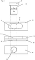
- the figures show a system comprising a first part 10, which is, by way of example, an angle bracket, and a second part 20, which is, by way of example, a girder, preferably a hollow metal girder.
- the first part 10 comprises a locking oblong hole 11.
- the locking oblong hole 11 is a through hole, which penetrates through the first part 10, and in accordance with the usual understanding of an oblong hole, it is longer than it is wide.
- the locking oblong hole 11 is provided with constrictions 12, which form local narrowings of the width of the locking oblong hole 11 for centring a threaded rod.
- the first part 10 furthermore comprises a pre-fixing oblong hole 15.
- the pre-fixing oblong hole 15 is a through hole, which penetrates through the first part 10, and in accordance with the usual understanding of an oblong hole, it is longer than it is wide.
- the pre-fixing oblong hole 15 preferably does not have constrictions 12
- the pre-fixing oblong hole 15 has a greater maximum width than has the locking oblong hole 11.
- the system furthermore comprises a locking threaded rod 30 and a pre-fixing threaded rod 50.
- Both the locking threaded rod 30 and the pre-fixing threaded rod 50 are externally threaded, wherein the thread dimensions of the locking threaded rod 30 and the pre-fixing threaded rod 50 are generally the same.
- the locking threaded rod 30 is provided with a screw head 39 and the pre-fixing threaded rod 50 with a screw head 59.
- the first part 10 is initially positioned adjacent to the second part 20.
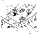
- the pre-fixing threaded rod 50 is passed through the pre-fixing oblong hole 15 and screwed into the second part 20.
- the pre-fixing threaded rod 50 can be tappingly screwed into a corresponding circular hole provided in the second part 20.
- the pre-fixing threaded rod 50 is tightened until its screw head 59 secures the first part 10 on the second part 20.
- the resulting state is shown in figure 1 .
- the pre-fixing threaded rod 50 is undersized with respect to the pre-fixing oblong hole 15, and the pre-fixing threaded rod 50 generally does not widen the pre-fixing oblong hole 15 as it is passed therethrough.
- the locking threaded rod 30 is screwingly passed through the locking oblong hole 11 and screwed into the second part 20.
- the locking threaded rod 30 can be tappingly screwed into a circular hole 22 provided in the second part 20.
- the locking threaded rod 30 is tightened until its screw head 39 hits the first part 10.
- Figure 2 shows the system before the above-mentioned this process
- figure 1 shows the system during this process
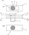
- figure 3 shows the system at the end of this process.
- the locking threaded rod 30 is oversized with respect to the locking oblong hole 11.
- both the major diameter d maj and the minor diameter d min of the locking threaded rod 30 are oversized with respect to the locking oblong hole 11, but an embodiment in which only the major diameter d maj is oversized with respect to the locking oblong hole 11 could also be envisaged as an alternative. Since the locking threaded rod 30 is oversized with respect to the locking oblong hole 11, the locking threaded rod 30 threadedly cuts into the hole walls of the locking oblong hole 11 and locally widens the locking oblong hole 11. Consequently, a global width maximum 95 is formed where the locking threaded rod 30 penetrates through the locking oblong hole 11. The locking threaded rod 30 engaging into the global width maximum 95 can provide particularly good lateral locking.
- the locking threaded rod 30 is also oversized with respect to the circular hole 22. Therefore, the locking threaded rod 30 also widens the circular hole 22 as it is passed into the second part 20.
- the locking oblong hole 11 could, for example, have a slot width of 7mm if the wall strength of the first part 10 is 3mm, and of 8mm if the wall strength of the first part 10 is 4mm.
- the locking oblong hole 11 can be used multiple times in different positions to allow repositioning. This can be assisted by the constrictions 12.
- the locking oblong hole 11 might have extension at its opposing ends, which counteract a tendency of the locking threaded rod 30 to move within the locking oblong hole 11 when cutting one of the opposing ends of the locking oblong hole 11 (i.e. when cutting not only the opposite walls of the locking oblong hole 11, but also one of its end walls).
Landscapes
- Engineering & Computer Science (AREA)
- General Engineering & Computer Science (AREA)
- Mechanical Engineering (AREA)
- Architecture (AREA)
- Physics & Mathematics (AREA)
- Electromagnetism (AREA)
- Civil Engineering (AREA)
- Structural Engineering (AREA)
- Connection Of Plates (AREA)
Priority Applications (6)
| Application Number | Priority Date | Filing Date | Title |
|---|---|---|---|
| EP20188624.9A EP3945221A1 (fr) | 2020-07-30 | 2020-07-30 | Utilisation d'une tige filetée surdimensionnée dans un trou de verrouillage oblong et arrangement |
| CN202180046478.6A CN115735063B (zh) | 2020-07-30 | 2021-07-20 | 在锁定长圆孔中使用过大螺纹杆 |
| PCT/EP2021/070241 WO2022023120A1 (fr) | 2020-07-30 | 2021-07-20 | Utilisation d'une tige filetée surdimensionnée dans un trou oblong de verrouillage |
| EP21742445.6A EP4189255B1 (fr) | 2020-07-30 | 2021-07-20 | Utilisation d'une tige filetée surdimensionnée dans un trou de verrouillage oblong et arrangement |
| KR1020217038075A KR102770281B1 (ko) | 2020-07-30 | 2021-07-20 | 잠금용 장방형 홀에 과대한 크기의 스레드형 로드의 사용 |
| US18/007,150 US12253105B2 (en) | 2020-07-30 | 2021-07-20 | Use of an oversized threaded rod in a locking oblong hole |
Applications Claiming Priority (1)
| Application Number | Priority Date | Filing Date | Title |
|---|---|---|---|
| EP20188624.9A EP3945221A1 (fr) | 2020-07-30 | 2020-07-30 | Utilisation d'une tige filetée surdimensionnée dans un trou de verrouillage oblong et arrangement |
Publications (1)
| Publication Number | Publication Date |
|---|---|
| EP3945221A1 true EP3945221A1 (fr) | 2022-02-02 |
Family
ID=71894684
Family Applications (2)
| Application Number | Title | Priority Date | Filing Date |
|---|---|---|---|
| EP20188624.9A Withdrawn EP3945221A1 (fr) | 2020-07-30 | 2020-07-30 | Utilisation d'une tige filetée surdimensionnée dans un trou de verrouillage oblong et arrangement |
| EP21742445.6A Active EP4189255B1 (fr) | 2020-07-30 | 2021-07-20 | Utilisation d'une tige filetée surdimensionnée dans un trou de verrouillage oblong et arrangement |
Family Applications After (1)
| Application Number | Title | Priority Date | Filing Date |
|---|---|---|---|
| EP21742445.6A Active EP4189255B1 (fr) | 2020-07-30 | 2021-07-20 | Utilisation d'une tige filetée surdimensionnée dans un trou de verrouillage oblong et arrangement |
Country Status (5)
| Country | Link |
|---|---|
| US (1) | US12253105B2 (fr) |
| EP (2) | EP3945221A1 (fr) |
| KR (1) | KR102770281B1 (fr) |
| CN (1) | CN115735063B (fr) |
| WO (1) | WO2022023120A1 (fr) |
Citations (3)
| Publication number | Priority date | Publication date | Assignee | Title |
|---|---|---|---|---|
| GB191217400A (en) * | 1911-07-31 | 1912-12-23 | Arthur Kokkelkoren | Improvements in and relating to Bolts and Nuts. |
| US5093976A (en) * | 1990-08-13 | 1992-03-10 | General Motors Corporation | Method of mounting trim to a motor vehicle |
| US8555592B2 (en) * | 2011-03-28 | 2013-10-15 | Larry Randall Daudet | Steel stud clip |
Family Cites Families (12)
| Publication number | Priority date | Publication date | Assignee | Title |
|---|---|---|---|---|
| GB174000A (en) | 1921-04-13 | 1922-01-19 | Roland Victor Philpott | An improved wind-screen for motor-cycle side-cars |
| US4754857A (en) * | 1982-06-07 | 1988-07-05 | Eaton Corporation | Universal air chamber mounting bracket |
| US4911386A (en) * | 1988-05-27 | 1990-03-27 | Scosche Industries, Inc. | Multiple radio in-dash installation kit |
| US6837009B1 (en) * | 2003-05-12 | 2005-01-04 | Steven A. Roth | Brace for restricting relative movement between a rod and building structure |
| US8523119B1 (en) * | 2003-08-26 | 2013-09-03 | Securus, Inc. | Pipe support bracket |
| DE202005007418U1 (de) * | 2005-05-10 | 2005-07-21 | BSH Bosch und Siemens Hausgeräte GmbH | Gehäuse für ein elektrisches Gerät |
| US8172280B2 (en) * | 2008-05-16 | 2012-05-08 | Fischer Herbert J | Sheet metal corner for duct flanges |
| CN201250822Y (zh) * | 2008-07-14 | 2009-06-03 | 南车四方机车车辆股份有限公司 | 一种安装偏位调节装置 |
| DE202011004721U1 (de) * | 2011-04-01 | 2011-06-09 | Ruia Global Fasteners AG, 41462 | Elektrisch leitende Schraubverbindung und Spezialbuchse für eine solche Schraubverbindung |
| EP3354246B1 (fr) | 2013-02-11 | 2019-10-23 | Ferno-Washington, Inc. | Système d'assemblage d'équipement |
| FR3055034B1 (fr) * | 2016-08-12 | 2019-05-17 | Lisi Aerospace | Fixation a anneau lubrifiant pour pose en interference et procede d'assemblage au moyen d'une telle fixation |
| US10724229B2 (en) * | 2016-09-02 | 2020-07-28 | Simpson Strong-Tie Company, Inc. | Slip clip |
-
2020
- 2020-07-30 EP EP20188624.9A patent/EP3945221A1/fr not_active Withdrawn
-
2021
- 2021-07-20 KR KR1020217038075A patent/KR102770281B1/ko active Active
- 2021-07-20 US US18/007,150 patent/US12253105B2/en active Active
- 2021-07-20 CN CN202180046478.6A patent/CN115735063B/zh active Active
- 2021-07-20 WO PCT/EP2021/070241 patent/WO2022023120A1/fr not_active Ceased
- 2021-07-20 EP EP21742445.6A patent/EP4189255B1/fr active Active
Patent Citations (3)
| Publication number | Priority date | Publication date | Assignee | Title |
|---|---|---|---|---|
| GB191217400A (en) * | 1911-07-31 | 1912-12-23 | Arthur Kokkelkoren | Improvements in and relating to Bolts and Nuts. |
| US5093976A (en) * | 1990-08-13 | 1992-03-10 | General Motors Corporation | Method of mounting trim to a motor vehicle |
| US8555592B2 (en) * | 2011-03-28 | 2013-10-15 | Larry Randall Daudet | Steel stud clip |
Also Published As
| Publication number | Publication date |
|---|---|
| US20230228285A1 (en) | 2023-07-20 |
| EP4189255A1 (fr) | 2023-06-07 |
| EP4189255B1 (fr) | 2025-06-25 |
| CN115735063B (zh) | 2026-04-03 |
| WO2022023120A1 (fr) | 2022-02-03 |
| KR102770281B1 (ko) | 2025-02-18 |
| US12253105B2 (en) | 2025-03-18 |
| KR20220016069A (ko) | 2022-02-08 |
| CN115735063A (zh) | 2023-03-03 |
| EP4189255C0 (fr) | 2025-06-25 |
Similar Documents
| Publication | Publication Date | Title |
|---|---|---|
| US8920093B2 (en) | Thread-furrowing screw | |
| US2631809A (en) | Furring hanger | |
| EP2920476B1 (fr) | Elément de fixation et de suspension combiné | |
| US9512573B2 (en) | Bridge tie fastener system | |
| US20020114682A1 (en) | Concrete screw | |
| EP4189255B1 (fr) | Utilisation d'une tige filetée surdimensionnée dans un trou de verrouillage oblong et arrangement | |
| EP2478163A1 (fr) | Rail d'ancrage à noyer | |
| US10392758B2 (en) | Bridge tie fastener system | |
| CN201777373U (zh) | 用于船舶建造中的可调式大肋板防倾倒装置 | |
| US20190360513A1 (en) | Tension Bracket | |
| JP4740805B2 (ja) | 吊り金具用補強金具 | |
| DE202009011219U1 (de) | Verbindungsvorrichtung zwischen einem Decken- und Trennwandaufbau | |
| EP3387310B1 (fr) | Dispositif de serrage de tuyau adapté à une plage de diamètres de tuyau | |
| US770022A (en) | Bolt-anchor. | |
| EP4435221B1 (fr) | Crochet de fixation de châssis, ensemble de montage, châssis et procédé de montage | |
| JP5378253B2 (ja) | 鋼殻構造物の内装パネル取付構造及び内装パネル施工方法 | |
| DE8707767U1 (de) | Vorrichtung zum Befestigen von Rohrleitungen od.dgl. | |
| KR200358950Y1 (ko) | 일체형 앵커 볼트 | |
| JP3121581U (ja) | 吊り金具用補強金具 | |
| CA2997072C (fr) | Support de tension | |
| JP2008014328A (ja) | 吊り金具用補強金具 | |
| JP2016204910A (ja) | 鉄筋交差部締結具 | |
| FI20235178A1 (en) | BALCONY RAIL CONNECTOR ANCHORING DEVICE | |
| JP2008144460A (ja) | 断熱材固定金物及び金物 | |
| JP2019116829A (ja) | アンカーボルト及びアンカーボルトの施工方法 |
Legal Events
| Date | Code | Title | Description |
|---|---|---|---|
| PUAI | Public reference made under article 153(3) epc to a published international application that has entered the european phase |
Free format text: ORIGINAL CODE: 0009012 |
|
| STAA | Information on the status of an ep patent application or granted ep patent |
Free format text: STATUS: THE APPLICATION HAS BEEN PUBLISHED |
|
| AK | Designated contracting states |
Kind code of ref document: A1 Designated state(s): AL AT BE BG CH CY CZ DE DK EE ES FI FR GB GR HR HU IE IS IT LI LT LU LV MC MK MT NL NO PL PT RO RS SE SI SK SM TR |
|
| STAA | Information on the status of an ep patent application or granted ep patent |
Free format text: STATUS: THE APPLICATION IS DEEMED TO BE WITHDRAWN |
|
| 18D | Application deemed to be withdrawn |
Effective date: 20220803 |