EP3945237B1 - Dispositif de surveillance et procédé de fonctionnement d'un dispositif de surveillance - Google Patents
Dispositif de surveillance et procédé de fonctionnement d'un dispositif de surveillance Download PDFInfo
- Publication number
- EP3945237B1 EP3945237B1 EP20188684.3A EP20188684A EP3945237B1 EP 3945237 B1 EP3945237 B1 EP 3945237B1 EP 20188684 A EP20188684 A EP 20188684A EP 3945237 B1 EP3945237 B1 EP 3945237B1
- Authority
- EP
- European Patent Office
- Prior art keywords
- sensor
- monitoring device
- muting
- function
- sensor means
- Prior art date
- Legal status (The legal status is an assumption and is not a legal conclusion. Google has not performed a legal analysis and makes no representation as to the accuracy of the status listed.)
- Active
Links
Images





Classifications
-
- F—MECHANICAL ENGINEERING; LIGHTING; HEATING; WEAPONS; BLASTING
- F16—ENGINEERING ELEMENTS AND UNITS; GENERAL MEASURES FOR PRODUCING AND MAINTAINING EFFECTIVE FUNCTIONING OF MACHINES OR INSTALLATIONS; THERMAL INSULATION IN GENERAL
- F16P—SAFETY DEVICES IN GENERAL; SAFETY DEVICES FOR PRESSES
- F16P3/00—Safety devices acting in conjunction with the control or operation of a machine; Control arrangements requiring the simultaneous use of two or more parts of the body
- F16P3/12—Safety devices acting in conjunction with the control or operation of a machine; Control arrangements requiring the simultaneous use of two or more parts of the body with means, e.g. feelers, which in case of the presence of a body part of a person in or near the danger zone influence the control or operation of the machine
- F16P3/14—Safety devices acting in conjunction with the control or operation of a machine; Control arrangements requiring the simultaneous use of two or more parts of the body with means, e.g. feelers, which in case of the presence of a body part of a person in or near the danger zone influence the control or operation of the machine the means being photocells or other devices sensitive without mechanical contact
- F16P3/144—Safety devices acting in conjunction with the control or operation of a machine; Control arrangements requiring the simultaneous use of two or more parts of the body with means, e.g. feelers, which in case of the presence of a body part of a person in or near the danger zone influence the control or operation of the machine the means being photocells or other devices sensitive without mechanical contact using light grids
-
- F—MECHANICAL ENGINEERING; LIGHTING; HEATING; WEAPONS; BLASTING
- F16—ENGINEERING ELEMENTS AND UNITS; GENERAL MEASURES FOR PRODUCING AND MAINTAINING EFFECTIVE FUNCTIONING OF MACHINES OR INSTALLATIONS; THERMAL INSULATION IN GENERAL
- F16P—SAFETY DEVICES IN GENERAL; SAFETY DEVICES FOR PRESSES
- F16P3/00—Safety devices acting in conjunction with the control or operation of a machine; Control arrangements requiring the simultaneous use of two or more parts of the body
- F16P3/12—Safety devices acting in conjunction with the control or operation of a machine; Control arrangements requiring the simultaneous use of two or more parts of the body with means, e.g. feelers, which in case of the presence of a body part of a person in or near the danger zone influence the control or operation of the machine
- F16P3/14—Safety devices acting in conjunction with the control or operation of a machine; Control arrangements requiring the simultaneous use of two or more parts of the body with means, e.g. feelers, which in case of the presence of a body part of a person in or near the danger zone influence the control or operation of the machine the means being photocells or other devices sensitive without mechanical contact
- F16P3/147—Safety devices acting in conjunction with the control or operation of a machine; Control arrangements requiring the simultaneous use of two or more parts of the body with means, e.g. feelers, which in case of the presence of a body part of a person in or near the danger zone influence the control or operation of the machine the means being photocells or other devices sensitive without mechanical contact using electro-magnetic technology, e.g. tags or radar
Definitions
- the invention relates to a monitoring device according to the preamble of claim 1.
- Such monitoring devices are used in the field of safety technology, whereby the safety sensor is generally used to monitor the danger area of a hazardous system, whereby the term system generally also includes machines, robots and the like.
- the monitoring device is used to secure access to a danger area of a plant, whereby access to the danger area is via a conveyor system.
- the monitoring device typically has a light curtain as a safety sensor, which is used to monitor a protective field lying on one level.
- the light curtain generates a switching signal, the switching states of which indicate whether an object is present in the protective field or not. If an object is detected in the protective field by the light curtain, a safety function is triggered by the corresponding switching signal.
- the switching signal is used to control a control unit of the system, which shuts it down so that no more dangers can arise from the system.
- the conveyor system is generally also used to transport permissible objects such as goods stored on pallets that are required to carry out the plant's work processes. Since such permissible objects are not safety-critical, the safety function would be triggered if the movement of permissible objects through the protective field of the light curtain can lead to an unnecessary standstill of the machine.
- muting sensors are arranged upstream of the safety sensor in known monitoring devices in the conveying direction. If an object is detected as a permissible object by the muting sensors, the safety sensor is bypassed for a specified period of time so that it no longer triggers the safety function when the permissible object passes through the protective field.
- Such muting sensors are typically formed by light barrier arrangements. With such light barrier arrangements, permissible objects often cannot be reliably detected.
- Another disadvantage is that the timing and evaluation of the signals from the muting sensors is inaccurate, since the time at which the muting sensors detect objects must be extrapolated based on the conveyor speed to determine how long it will take until the permitted object has actually passed the safety sensor.
- the actual conveyor speed cannot always be set or known exactly.
- This signal can be generated, for example, by the control of the conveyor system that transports permissible objects.
- Muting of the safety sensor is preferably started with the start of the external control signal.
- the condition for maintaining muting can be defined as a requirement that the safety sensor registers an object intrusion in the protective field within a certain time interval after the start of the control signal.
- the EP 3 633 413 A1 relates to a safety arrangement with a light curtain for detecting objects in a monitoring area with an arrangement of beam axes, each of which is formed by a transmitter emitting light beams and at least one associated receiver.
- the monitoring area is monitored with the beam axes or with an area scanner, in which light beams emitted by a transmitter sweep over the monitoring area.
- the monitoring area is divided into at least one protection area and at least one muting control area, whereby muting functions can be controlled depending on object detection in the muting control area. If an object is detected in the protection area, a safety output signal is only generated if muting is not activated.
- the JP 2010 133 503 A relates to a safety system with a light curtain and a muting sensor that is connected to a controller.
- the muting sensor includes a read/write unit that is used to read RFID tags on workpieces.
- the EN 10 2016 116 828 A1 relates to a safety light curtain for monitoring a danger zone of a machine or system, comprising a transmitting unit with a plurality of light transmitters emitting light beams and a receiving unit with a plurality of light receivers receiving light beams for monitoring a protective field.
- a control and evaluation unit is designed to generate a shutdown signal for the machine or system as a safety function when an impermissible object is detected in the protective field.
- the control and evaluation unit is designed to activate a bridging sub-area when a permissible object is detected and not to generate a shutdown signal as long as the permissible object is within the bridging sub-area, wherein an interruption of a light beam in at least one predetermined first sub-area of the safety light curtain is a detection of a permissible object.
- the invention is based on the object of providing a monitoring device of the type mentioned above, which has a high level of functionality and at the same time a high level of functional reliability despite its structurally simple design.
- the invention relates to a monitoring device with a sensor, by means of which object monitoring is carried out in a protective field.
- a safety function is triggered in the protective field.
- means are provided for generating a bridging function, by means of which at least part of the protective field is bridged so that an object intervention does not trigger the safety function there.
- sensor means are provided for detecting the path of a movable unit, in which marking elements of the movable unit that are repeatedly guided into its detection area are detected, wherein the bridging function is controlled and/or monitored based on the path detection.
- the invention further relates to a corresponding method.
- the monitoring device according to the invention is generally used for monitoring a danger area on a hazardous system.
- the monitoring device is particularly advantageously used to secure access to a danger area, with access to the danger area being achieved in particular via a transport device.
- the monitoring device advantageously forms a safety system that meets the safety requirements for use in safety-relevant Applications, especially in the area of personal protection.
- the components of the safety system have a fail-safe design. This is achieved in particular by a redundant, multi-channel design of the sensor's evaluation unit, so that the sensor forms a safety sensor.
- the monitoring device advantageously comprises a control system which is used in particular to control the system monitored by the sensor.
- the control system is then designed as a safety control system and also has a redundant, multi-channel structure.
- the central safety component of the monitoring device is the sensor, which is designed in particular as a safety sensor, with which a protective field is monitored, which advantageously runs in one plane.
- the safety sensor generates a binary switching signal whose switching states indicate whether an object is in the protective field or not. If the safety sensor registers an object intrusion in the protective field, the switching signal triggers a safety function, for example, the system is shut down so that it no longer poses any danger.
- a bridging function i.e. a muting function
- the safety sensor is completely or partially bridged, i.e. muted, so that the transport goods can pass through the protective field without the safety sensor triggering the safety function.
- sensor means are used to detect the path of a movable unit which is generally designed to feed permissible objects into the danger zone of the system, whereby the permissible objects pass through the protective field monitored by the safety sensor.
- the bridging function i.e. the muting function
- the bridging function is controlled and/or monitored by the position detection using the sensors. This significantly increases the safety and reliability of the muting function.
- the movable unit is advantageously formed by a transport device.
- First sensor means are provided, by means of which an incremental path detection is carried out by detecting marking elements on the transport device or on a drive train of the transport device.
- second sensor means are advantageously provided, by means of which an absolute path reference is generated by detecting reference elements.
- the reference elements are advantageously formed by elements of permissible objects transported on the transport device, such as transport racks or containers for these objects, wherein the bridging function is designed such that the permissible objects pass through the protective field without the safety function being triggered.
- the position of a permissible object can be reliably detected and, based on this, the path that the permissible object travels to the safety sensor can be determined.
- the muting function can thus be adapted precisely to the movement sequence of the permissible object, whereby the muting function is advantageously activated when the permissible object passes through the protective field, thereby avoiding unnecessary triggering of the safety function by the permissible object.
- the safety sensor can be designed as an optical sensor or a radar sensor.
- the optical sensor is an area distance sensor or a light curtain.
- the sensor means are designed in the form of optical, magnetic, inductive or capacitive sensor means.
- acoustic sensors such as ultrasonic sensors, optical sensors or radar sensors with evaluation of the reflected frequency can be used.
- the speed of the means of transport can be determined very easily using Doppler effects.
- the marking elements and/or the first sensor means are designed for detecting the direction of the movable unit.
- marking elements can comprise a sequence of geometric structure elements and/or material structure elements, which are detected serially by means of the first sensor means.
- the first sensor means can each have at least two sensor elements arranged one behind the other in the direction of movement of the movable unit.
- the speed of the moving unit is also advantageously determined based on sensor signals from the sensor means.
- the sensor means generate pulse-shaped sensor signals.
- the speed of the moving unit including the transport device, can be easily determined from the temporal sequence of the pulse-shaped sensor signals obtained when the marking elements are detected.
- control of the bridging function includes initiating and/or terminating a muting.
- This control is carried out in such a way that a permissible object on the transport device is conveyed through the protective field without the safety sensor triggering the safety function.
- control of the bridging function includes the specification of different bridged partial protective fields.
- Muting is particularly advantageous if it is only maintained when a specific sequence of protective field interruption patterns is registered depending on path signals determined by the sensor means.
- the bridged part of the protective field is continuously adapted to the contour of the permissible object passing through the protective field, which on the one hand ensures that the penetration of the permissible object into the protective field does not trigger the safety function.
- the area of the protective field not covered by permissible objects is not bridged, so that object interventions there trigger the protective fields. This further increases the safety of the monitoring device, as manipulations such as a person sitting on the permissible objects attempts to pass through the protective field of the safety sensor unnoticed, will be detected and lead to the triggering of the safety function.
- the bridging function is controlled depending on the path, speed and/or direction signals generated by the sensor means.
- the bridging function is controlled directly depending on the path detection carried out with the sensor means, whereby this in particular detects the supply of a permissible object to the protective field of the safety sensor.
- the reliability of the detection of the movement of the transport device and in particular of a permissible object transported on it is further increased by additional direction detection and speed determination.
- control of the bridging function is dependent on external signals from a control of the bridging function and/or from muting sensors.
- the bridging function can also be controlled depending on sensor signals from the sensor.
- signals for controlling the bridging function are monitored by position detection using the sensor means.
- the position detection carried out with the sensors enables control of the muting function, thereby increasing the safety of the monitoring device.
- a muting timeout is provided in the monitoring device according to the invention.
- the muting timeout generally provides a control function for the muting. If If muting does not end at the scheduled time due to a fault in the monitoring device and therefore takes too long, dangerous situations can arise in which people or safety-critical objects pass through the protective field of the safety sensor into the danger area of the system without the safety function being triggered.
- the duration of muting is limited to a maximum value by the muting timeout.
- a time-related muting timeout can be provided, i.e. a maximum muting time duration is defined.
- a position window can also be specified and monitored instead of specifying the muting timeout.
- a time window monitored muting timeout can be suspended if a speed of the moving unit determined from sensor signals falls below a limit value.
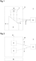
- FIGS 1 - 3 show examples of a sensor 1 for a monitoring device 100, as shown by way of example in Figures 4a,b and 10 - 15.
- the sensors 1 can be designed as radar sensors.
- Sensors 1 are shown in the form of optical sensors.
- Figure 1 shows an embodiment of an optical sensor in the form of an area distance sensor, i.e. a scanning distance sensor.
- the optical sensor has a transmitter 3 that emits light rays 2 and a receiver 4 that receives light rays 2.
- the transmitter 3 emits light rays 2 in the form of light pulses.
- the light rays 2 are reflected by an object 5 to be detected, with the corresponding light travel time of the light pulses to the object 5 and back to the optical sensor being evaluated for the distance determinations.
- the sensor components of the optical sensors are integrated in a housing 6, with the transmitter 3 and the receiver 4 being connected to a upstream receiving optics 7 are arranged stationary in the housing 6.
- the optical sensor detects objects in a flat detection area by periodically deflecting the light beams 2 by means of a deflection unit 8.
- the light beams 2 cover a detection area within a period.
- the deflection unit 8 is motor-driven and comprises a deflection mirror 9 which can be rotated about an axis of rotation D and on which the light beams 2 are deflected.
- Figure 2 shows a variant of the area distance sensor according to Figure 1
- the periodic deflection of the light beams 2 is achieved by arranging the transmitter 3 and the receiver 4 in a measuring head 10 which can rotate about an axis of rotation D, the measuring head 10 being rotatably mounted on a base 11.
- each optical sensor is assigned an evaluation unit (not shown) in which the received signals of the receiver 4 are evaluated.
- the optical sensors are designed in accordance with Figures 1 and 2 They are designed as safety sensors and have a fail-safe structure, which can be implemented, for example, by a redundant evaluation unit in the form of two computer units that cyclically monitor each other.
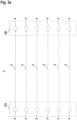
- Figure 3a shows an example of a sensor 1 in the form of a light curtain.
- the light curtain has a series arrangement of transmitters 3 emitting light beams 2 in a first housing 12a and a series arrangement of receivers 4 in a second housing 12b.
- the light beams 2 span a flat monitoring area that is oriented in a vertical plane and thus runs perpendicular to the horizontal surface of the conveyor belt of the conveyor device.
- the transmitters 3 are activated cyclically one after the other using a transmitter control (not shown).
- the receivers 4 are optically synchronized to the transmitters 3 in a known manner.
- the reception signals generated in the receivers 4 are evaluated in an evaluation unit (not shown) to generate a binary switching signal.
- the switching states of the switching signal indicate whether an object 5 is in the monitoring area or not. If the monitoring area is clear, the light beams 2 of all transmitters 3 hit the assigned receiver 4 unhindered. If an object intervenes in the monitoring area, the light beams 2 of at least one transmitter 3 are interrupted by the object 5.
- the evaluation unit has a redundant, preferably two-channel structure.
- Figure 3b shows an example of a variant of a sensor 1 in the form of a light curtain with deflecting mirrors 38.
- the light curtain has a series arrangement of transmitters 3 emitting light beams 2 in a first housing 12 and a receiver 4 in the same housing 12. In general, a series arrangement of receivers 4 can also be provided.
- the light beams 2 span a flat monitoring area that is oriented in a vertical plane and thus runs perpendicular to the horizontal surface of the conveyor belt of the conveyor device.
- deflecting mirrors 38 are mounted, which deflect the light beams 2 of the transmitter 3 into light beams 2b for the receiver 4.
- the transmitters 3 are activated cyclically one after the other by means of a transmitter control (not shown).
- the receiver 4 is synchronized electrically or optically to the transmitters 3 in a known manner.
- the reception signals generated in the receivers 4 are evaluated in an evaluation unit (not shown) to generate a binary switching signal.
- the switching states of the switching signal indicate whether an object 5 is in the monitoring area or not. If the monitoring area is clear, the light beams 2 of all transmitters 3 hit the assigned receiver 4 without hindrance. If an object intervenes in the monitoring area, the light beams 2 of at least one transmitter 3 are interrupted by the object 5.
- the evaluation unit has a redundant, preferably two-channel structure.
- FIG 4 shows an embodiment of the monitoring device 100 according to the invention.
- the monitoring device 100 serves to secure a danger zone 13 of a system 14. Access to the danger zone 13 is only possible via a movable unit in the form of a transport device 15, which in the present case is designed in the form of a conveyor belt.
- the transport device 15 is driven by means of a drive (not shown).
- the system 14 and the transport device 15 are controlled by a safety control 16.
- Access to the danger zone 13 is monitored by means of a sensor 1 in the form of a light curtain.
- the light beams 2 of the light curtain monitor a protective field 17.
- a binary switching signal with a switching state is generated that triggers a safety function.
- the switching signal is output to the safety controller 16.
- the safety function is formed by the system 14 being shut down.
- permissible objects 5 in the form of transport goods 18 are transported in a transport direction I. These permissible objects 5 are not dangerous and should be protected by the protective field 17 of the Light curtains can be passed through to system 14 without the safety function being triggered.
- a bridging function i.e. a muting function, is provided by means of which the sensor 1 is bridged so that it does not trigger a safety function when a transport item 18 passes the protective field 17.
- the entire protective field 17 can be bridged or, in the case of partial muting, only the part 17' of the protective field 17 within which the transport goods 18 are located. If the contours of the transport goods vary, the bridged part 17 ⁇ of the protective field 17 also varies.
- the muting function is controlled or monitored depending on a position detection carried out with sensor means 19, 20.
- the sensor means 19, 20 are designed in the form of optical, magnetic, inductive or capacitive sensor means 19, 20.
- the sensor means 19, 20 generate pulse-shaped sensor signals.
- the speed of the moving unit can be determined based on sensor signals from the sensor means 19, 20.
- the sensors 19, 20 can be designed as radar sensors, optical sensors or ultrasonic sensors.
- Speed signals and direction signals can thus be determined by evaluating the Doppler effect, i.e. the change in frequency of the reflected waves compared to the emitted wave. From the speed signal determined in this way, path information can be determined by summing up the speed signal.
- Figure 5a shows a section of the transport device 15 with several conveyor belt elements 21, which are moved by means of the drive in the direction indicated by the arrows I, II marked directions. Edges 22 protruding from the undersides of the conveyor belt elements 21 form marking elements which are detected by first sensor means 19.
- these first sensor means 19 have two sensor elements 19a, 19b arranged one behind the other in the conveying direction of the transport device 15.
- Figure 5b shows a sensor arrangement with an ultrasonic sensor 19c with a transmitted ultrasonic wave 191 with a first specific frequency and a received ultrasonic wave 192 with a frequency that changes depending on the speed of the transport device. From the frequency change of the received signal, both the direction and the speed of the transport device can be determined. By adding up the speed values, path information can be obtained.
- a radar sensor can also be provided.
- path information is obtained, and the speed of the transport device 15 is determined by the time intervals between the sensor signals.
- the transport direction of the transport device is determined by evaluating the sequence of the sensor signals of the sensor elements 19a, 19b.
- Figure 7 shows a modification of the embodiment according to Figure 5 .
- the sensor means 19 have only one sensor element 19a, so that in this case no direction detection is possible.
- the evaluation of the temporal course of the sensor signals 19a otherwise takes place analogously to the embodiment according to the Figures 6a, 6b .
- Figure 9 shows a modification of the embodiment according to Figure 7 such that the conveyor belt elements 21 have different marking elements in the form of edges 22, 22'.
- the first sensor means 19 again have only one sensor element 19a, direction detection is again possible based on the different sensor signals generated by the different edges 22, 22'.
- Figure 10a shows the sensor signals of the sensor element 19a for the transport direction I.
- Figure 10b shows the sensor signals of the sensor element 19a for the transport direction II.
- Figure 11 shows a variant of the transport device 15 with a drive in the form of a toothed belt drive 23 with a toothed belt 24. Marking elements in the form of elevations 25 or depressions 26 can be provided on the toothed belt 24, which are scanned with first sensor means 19.
- marking elements can also be provided on the drive axis 27 of the toothed belt drive.
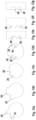
- FIGS. 12a - 12g show different embodiments of such marking elements, whereby the Figures 12a - 12d show a plan view of the front wheel area of the drive axle 27, whereas the Figures 12e - 12g Show longitudinal sectional views.
- Figures 12a, 12b show marking elements forming geometric structure elements in the form of elevations 25, while the figures show marking elements in the form of depressions 26.
- Figure 12g shows marking elements in the form of material structure elements 28. These form local areas with different material properties than the surrounding area, whereby these material structure elements 28 can be detected with the first sensor means 19.
- control of the muting function in particular the initiation and termination of the muting, is carried out solely as a function of the incremental position detection by means of the first sensor means 19.
- a referencing of the first sensor means 19 to absolute positions is advantageously provided.
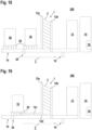
- FIG. 18 An example of this is Figure 18 .
- the transport goods are stored on pallets 29.
- second sensor means 20 are provided, by means of which pallet feet of the pallets 29 are detected, whereby an absolute path reference is obtained for the individual permissible objects 5.
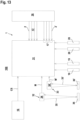
- Figure 13 shows a further embodiment of the monitoring device 100 according to the invention in the form of a block diagram.
- Figure 13 shows the safety sensor in the form of a light curtain with a transmitter unit 30 having the transmitters 3 and a receiver unit 31 having the receivers 4.
- a controller is integrated in the receiver unit 31, which forms the evaluation unit and takes over the muting control.
- the controller 16 of the system 14 is connected to the receiver unit 31 and supplies an external control signal CS to the receiver unit 31.
- muting sensors 32, 33 designed as reflective light barriers are provided, which generate muting signals M, M ⁇ , which are also read into the receiver unit 31.
- the muting signals each have a housing 34, 34' with a transmitting element and a receiving element integrated therein. Transmitted light beams 35, 35' emitted by the transmitting element are guided to a reflector 36, 36'.
- sensor signals generated by first sensor means 19 and second sensor means 20 are read into the receiver unit 31.
- the light curtain has further light barriers 2', which form a muting field as a protective field 17 ⁇ running in a horizontal plane.
- Figure 19 is an extension of the embodiment according to Figure 18 in that the vertically oriented housing 12a of the light curtain is extended by a horizontal housing section 12c. Accordingly, the housing 12b of the light curtain is extended by a horizontal section 12d.
- the transmitters 3 and receivers 4 generating the protective field 17 are arranged in the vertical housings 12a, 12b, the transmitters 3 and receivers 4 forming the muting field are integrated in the horizontal housing sections 12c, 12d. Otherwise, the embodiment according to Figure 19 corresponds to the embodiment according to Figure 18 .
- the Figures 14a - c show a first example of muting control.
- Figure 14a shows the temporal progression of the sensor signals of the first sensor means 19. By scanning periodically recurring marking elements, a periodic sequence of pulse-shaped sensor signals is generated with the first sensor means 19. These pulses mark small sections of the path, whereby the relative transport positions can be recorded.
- the binary external control signal CS is read by the safety controller 16 ( Figure 14b ).
- the switching signal PFI ( Figure 14c ) is evaluated.
- time t 2 corresponding to a transport position s 2 , the permissible object 5 for which the muting was initiated penetrates into the protective field 17 and is thus detected by the light curtain, whereby the switching signal PFI changes from the switching state "0" to the switching state "1".
- Muting is terminated when the control signal CS changes from the signal state "1" to "0" at a transport position s 4 , i.e. at time t 4 .
- the Figures 15a - d show a second example of muting control.
- the sensor signals of the first sensor means 19 correspond to the sensor signals of the first sensor means 19 according to the embodiment according to Figure 14a .
- the muting is controlled depending on the muting signals M, M' of the two muting sensors 32, 33.
- the muting sensors 32, 33 are arranged spatially offset in the transport direction of the transport device 15 in front of the light curtain.
- the signal state of the muting signals 32 M changes from “0” to "1” when a permissible object 5 is detected at time ti.
- the second muting sensor 33 detects the permissible object 5 somewhat later, so that the signal state M' of this muting sensor 33 changes from "0" to "1" at time t' 1 (>ti).
- the time interval t '1 - t 1 is monitored to ensure that it is smaller than the time interval between two adjacent pulses of the sensor signal.
- muting is terminated when the muting signals M, M' at the muting sensors 32, 33 change from "1" to "0".
- the signals of the muting field of the light curtain generated by the light beams 2' can also be used for muting control.
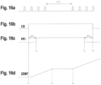
- FIGS 15a - 15d show another example of a muting control. Initiating and ending muting ( Figures 15a - 15c ) corresponds to the design of the Figures 14a - 14c .
- a muting timeout is provided, in which a muting timeout time counting signal ZZMT ( Figure 15d ) is generated.
- the counting process begins when muting is initiated at ti.
- the muting timeout represents a safety function such that the muting duration is limited to a maximum value. If the muting timeout counting signal reaches the maximum value, an error message is generated which leads to the shutdown of system 14.
- the transport device 15 is stationary during the time interval ⁇ t 3. During this time interval, the counting up of the signal ZZMT is stopped. The counting up of the signal ZZMT is only continued after ⁇ t' 3 has elapsed. This takes into account the fact that a stationary transport device 15 with the permissible object 5 in the protective field 17 of the light curtain does not represent a dangerous condition, so that the counting up of the signal ZZMT is not necessary during this time.
- Figure 17 shows a variant of the embodiment according to Figure 13 .
- the embodiment according to Figure 17 differs from the arrangement according to Figure 13 only because the muting control is relocated from the receiver unit 31 and integrated into a separate control unit 37.
Landscapes
- Engineering & Computer Science (AREA)
- General Engineering & Computer Science (AREA)
- Mechanical Engineering (AREA)
- Radar, Positioning & Navigation (AREA)
- Remote Sensing (AREA)
- Geophysics And Detection Of Objects (AREA)
Claims (24)
- Dispositif de surveillance (100) comportant un capteur (1) permettant de surveiller des objets dans un champ de protection (17), une fonction de sécurité étant déclenchée lorsqu'une intrusion d'objet est enregistrée dans le champ de protection (17), et des moyens étant prévus pour générer une fonction de pontage au moyen de laquelle au moins une partie (17') du champ de protection (17) est pontée, afin que l'intervention d'un objet n'entraîne pas le déclenchement de la fonction de sécurité, caractérisé par le fait que des capteurs (19, 20) sont prévus pour détecter la trajectoire d'une unité mobile, dans laquelle sont détectés les éléments de marquage de l'unité mobile qui sont guidés de manière répétée dans son champ de détection, et par le fait que la fonction de pontage est commandée et/ou surveillée sur la base de la détection de la trajectoire.
- Dispositif de surveillance (100) selon la revendication 1, caractérisé en ce que l'unité mobile est formée par un dispositif de transport (15), et en ce que des premiers moyens de détection (19) sont prévus, au moyen desquels une détection de trajectoire incrémentale est effectuée en détectant des éléments de marquage sur le dispositif de transport (15) ou sur un train d'entraînement du dispositif de transport (15).
- Dispositif de surveillance (100) selon la revendication 1, caractérisé en ce que l'unité mobile est formée par un dispositif de transport (15), et en ce que des premiers moyens de détection (19) sont prévus, au moyen desquels une vitesse est détectée en exploitant l'effet Doppler par la détection d'éléments de marquage sur le dispositif de transport (15) ou sur un train d'entraînement du dispositif de transport (15) et/ou une distance est additionnée à partir de la vitesse mesurée.
- Dispositif de surveillance (100) selon l'une des revendications 1 à 3, caractérisé par la présence de seconds moyens de détection (20) permettant de générer une référence de trajectoire absolue en détectant des éléments de référence.
- Dispositif de surveillance (100) selon la revendication 3, caractérisé par le fait que les éléments de référence sont formés par des éléments d'objets autorisés (5) transportés sur le dispositif de transport (15), la fonction de pontage étant conçue de manière à ce que les objets autorisés (5) traversent le champ de protection (17) sans que la fonction de sécurité ne soit déclenchée.
- Dispositif de surveillance (100) selon l'une des revendications 1 à 5, caractérisé par le fait que le capteur (1) est un capteur de sécurité.
- Dispositif de surveillance (100) selon l'une des revendications 1 à 6, caractérisé par le fait que le capteur (1) est un capteur optique ou un capteur radar.
- Dispositif de surveillance (100) selon la revendication 7, caractérisé par le fait que le capteur (1) est un rideau lumineux ou un capteur de distance.
- Dispositif de surveillance (100) selon l'une des revendications 1 à 8, caractérisé par le fait que les moyens de détection (19, 20) se présentent sous la forme de capteurs optiques, magnétiques, inductifs, capacitifs (19, 20), de radars ou de capteurs sonores.
- Dispositif de surveillance (100) selon l'une des revendications 1 à 9, caractérisé par le fait que les éléments de marquage et/ou les premiers moyens de détection (19) sont conçus pour la détection de la direction de l'unité mobile.
- Dispositif de surveillance (100) selon la revendication 10, caractérisé en ce que les éléments de marquage ont une séquence d'éléments structurels de géométrie et/ou d'éléments structurels de matériau (28) qui sont détectés en série au moyen des premiers moyens de détection (19).
- Dispositif de surveillance (100) selon l'une des revendications 10 ou 11, caractérisé par le fait que les premiers moyens de détection (19) comportent chacun au moins deux éléments de détection (19a, 19b) disposés l'un derrière l'autre dans la direction du mouvement de l'unité mobile.
- Dispositif de surveillance (100) selon l'une des revendications 1 à 12, caractérisé par le fait que la vitesse de l'unité mobile est déterminée au moyen des signaux des capteurs (19, 20).
- Dispositif de surveillance (100) selon l'une des revendications 1 à 13, caractérisé par le fait que les moyens de détection (19, 20) génèrent des signaux de détection en forme d'impulsion.
- Dispositif de surveillance (100) selon l'une des revendications 1 à 14, caractérisé par le fait que la commande de la fonction de pontage comprend l'initiation et/ou l'arrêt d'une inhibition.
- Dispositif de surveillance (100) selon l'une des revendications 1 à 15, caractérisé par le fait que la commande de la fonction de pontage comprend la spécification de différents champs de protection partiels pontés.
- Dispositif de surveillance (100) selon l'une des revendications 15 ou 16, caractérisé par le fait que la fonction de pontage est commandée en fonction des signaux de déplacement, de vitesse et/ou de direction générés par les moyens de détection (19, 20).
- Dispositif de surveillance (100) selon l'une des revendications 15 à 17, caractérisé par le fait que la fonction de pontage est commandée en fonction de signaux externes provenant d'un dispositive de commande et/ou de capteurs d'inhibition (32, 33).
- Dispositif de surveillance (100) selon l'une des revendications 15 à 18, caractérisé par le fait que la fonction de pontage est commandée en fonction des signaux du capteur (1).
- Dispositif de surveillance (100) selon l'une des revendications 17 ou 18, caractérisé par le fait que les signaux de commande de la fonction de pontage sont surveillés au moyen des capteurs (19, 20) en utilisant des fenêtres temporelles ou des fenêtres de parcours.
- Dispositif de surveillance (100) selon l'une des revendications 15 à 20, caractérisé par le fait qu'un délai d'inhibition commandé par une fenêtre temporelle ou une fenêtre de cheminement peut être prédéfini.
- Dispositif de surveillance (100) selon la revendication 21, caractérisé en ce qu'une temporisation d'inhibition surveillée par une fenêtre temporelle est suspendue lorsqu'une vitesse de l'unité mobile déterminée à partir des signaux des capteurs des moyens de détection (19, 20) tombe en dessous d'une valeur limite.
- Dispositif de surveillance (100) selon l'une des revendications 15 à 22, caractérisé par le fait que l'inhibition n'est maintenue que si une séquence spécifique de modèles d'interruption du champ de protection est enregistrée en fonction des signaux de trajectoire déterminés par les moyens de détection (19, 20).
- Procédé de fonctionnement d'un dispositif de surveillance (100) doté d'un capteur (1), permettant de surveiller des objets dans un champ de protection (17), dans lequel une fonction de sécurité est déclenchée lorsqu'une intrusion d'objet est enregistrée dans le champ de protection (17), et dans lequel des moyens sont prévus pour générer une fonction de pontage au moyen de laquelle au moins une partie (17') du champ de protection (17) est pontée, afin que l'intervention d'un objet n'entraîne pas le déclenchement de la fonction de sécurité, caractérisé par le fait que des capteurs (19, 20) sont prévus pour détecter la trajectoire d'une unité mobile, dans laquelle sont détectés les éléments de marquage de l'unité mobile qui sont guidés de manière répétée dans son champ de détection, et par le fait que la fonction de pontage est commandée et/ou surveillée sur la base de la détection de la trajectoire.
Priority Applications (1)
| Application Number | Priority Date | Filing Date | Title |
|---|---|---|---|
| EP20188684.3A EP3945237B1 (fr) | 2020-07-30 | 2020-07-30 | Dispositif de surveillance et procédé de fonctionnement d'un dispositif de surveillance |
Applications Claiming Priority (1)
| Application Number | Priority Date | Filing Date | Title |
|---|---|---|---|
| EP20188684.3A EP3945237B1 (fr) | 2020-07-30 | 2020-07-30 | Dispositif de surveillance et procédé de fonctionnement d'un dispositif de surveillance |
Publications (2)
| Publication Number | Publication Date |
|---|---|
| EP3945237A1 EP3945237A1 (fr) | 2022-02-02 |
| EP3945237B1 true EP3945237B1 (fr) | 2024-07-17 |
Family
ID=71894711
Family Applications (1)
| Application Number | Title | Priority Date | Filing Date |
|---|---|---|---|
| EP20188684.3A Active EP3945237B1 (fr) | 2020-07-30 | 2020-07-30 | Dispositif de surveillance et procédé de fonctionnement d'un dispositif de surveillance |
Country Status (1)
| Country | Link |
|---|---|
| EP (1) | EP3945237B1 (fr) |
Families Citing this family (1)
| Publication number | Priority date | Publication date | Assignee | Title |
|---|---|---|---|---|
| EP4276498B1 (fr) * | 2022-05-13 | 2024-08-21 | Leuze electronic GmbH + Co. KG | Dispositif de surveillance |
Family Cites Families (3)
| Publication number | Priority date | Publication date | Assignee | Title |
|---|---|---|---|---|
| JP2010133503A (ja) * | 2008-12-05 | 2010-06-17 | Omron Corp | 安全システム、ミューティングセンサ装置およびセーフティセンサ装置 |
| DE102016116828B4 (de) * | 2016-09-08 | 2021-05-06 | Sick Ag | Sicherheitslichtvorhang |
| EP3633413B1 (fr) * | 2018-10-02 | 2024-04-17 | Leuze electronic GmbH + Co. KG | Dispositif de sécurité |
-
2020
- 2020-07-30 EP EP20188684.3A patent/EP3945237B1/fr active Active
Also Published As
| Publication number | Publication date |
|---|---|
| EP3945237A1 (fr) | 2022-02-02 |
Similar Documents
| Publication | Publication Date | Title |
|---|---|---|
| EP1548351B1 (fr) | Dispositif de surveillance d'une zone de couverture près d'une machine | |
| DE4422497C2 (de) | Vorrichtung und Verfahren zum optoelektronischen Erfassen von Gegenständen | |
| EP1046925B1 (fr) | Dispositif optoélectronique | |
| EP3910230B1 (fr) | Dispositif de surveillance | |
| EP4151899B1 (fr) | Dispositif de surveillance | |
| DE10312972B3 (de) | Optischer Sensor | |
| EP3885635B1 (fr) | Dispositif de surveillance permettant de sécuriser l'accès à une zone dangereuse à l'aide d'un capteur de sécurité | |
| EP3633413B1 (fr) | Dispositif de sécurité | |
| EP1826589B1 (fr) | Capteur optique destiné à la surveillance d'une zone de sécurité | |
| EP3945237A1 (fr) | Dispositif de surveillance et procédé de fonctionnement d'un dispositif de surveillance | |
| EP3886068B1 (fr) | Dispositif de surveillance et procédé de fonctionnement un dispositif de surveillance | |
| EP3974699A1 (fr) | Dispositif de surveillance | |
| EP3910228B1 (fr) | Dispositif de surveillance et procédé de fonctionnement un dispositif de surveillance | |
| EP3919801B1 (fr) | Dispositif de surveillance | |
| EP3945238B1 (fr) | Dispositif de surveillance et procédé de fonctionnement d'un dispositif de surveillance | |
| EP4047256B1 (fr) | Dispositif de surveillance et procédé de sécurisation d'une zone dangereuse au moyen d'un dispositif de surveillance | |
| EP3671289A1 (fr) | Système de détection | |
| EP3862617B1 (fr) | Dispositif de sécurisation d'une zone dangereuse | |
| DE202022103201U1 (de) | Überwachungseinrichtung | |
| EP3910227B1 (fr) | Dispositif de surveillance et procédé de fonctionnement d'un dispositif de surveillance | |
| EP4365477B1 (fr) | Dispositif de surveillance | |
| EP3910229B1 (fr) | Dispositif de surveillance | |
| DE102006029643B4 (de) | Vorrichtung zur Überwachung eines Gefahrenbereichs | |
| DE102023115311B4 (de) | Zugangsabsicherungssystem | |
| DE102024128693A1 (de) | Überwachungseinrichtung |
Legal Events
| Date | Code | Title | Description |
|---|---|---|---|
| PUAI | Public reference made under article 153(3) epc to a published international application that has entered the european phase |
Free format text: ORIGINAL CODE: 0009012 |
|
| STAA | Information on the status of an ep patent application or granted ep patent |
Free format text: STATUS: REQUEST FOR EXAMINATION WAS MADE |
|
| 17P | Request for examination filed |
Effective date: 20210129 |
|
| AK | Designated contracting states |
Kind code of ref document: A1 Designated state(s): AL AT BE BG CH CY CZ DE DK EE ES FI FR GB GR HR HU IE IS IT LI LT LU LV MC MK MT NL NO PL PT RO RS SE SI SK SM TR |
|
| GRAP | Despatch of communication of intention to grant a patent |
Free format text: ORIGINAL CODE: EPIDOSNIGR1 |
|
| STAA | Information on the status of an ep patent application or granted ep patent |
Free format text: STATUS: GRANT OF PATENT IS INTENDED |
|
| GRAS | Grant fee paid |
Free format text: ORIGINAL CODE: EPIDOSNIGR3 |
|
| GRAA | (expected) grant |
Free format text: ORIGINAL CODE: 0009210 |
|
| STAA | Information on the status of an ep patent application or granted ep patent |
Free format text: STATUS: THE PATENT HAS BEEN GRANTED |
|
| INTG | Intention to grant announced |
Effective date: 20240606 |
|
| AK | Designated contracting states |
Kind code of ref document: B1 Designated state(s): AL AT BE BG CH CY CZ DE DK EE ES FI FR GB GR HR HU IE IS IT LI LT LU LV MC MK MT NL NO PL PT RO RS SE SI SK SM TR |
|
| REG | Reference to a national code |
Ref country code: CH Ref legal event code: EP |
|
| REG | Reference to a national code |
Ref country code: DE Ref legal event code: R096 Ref document number: 502020008564 Country of ref document: DE |
|
| REG | Reference to a national code |
Ref country code: IE Ref legal event code: FG4D Free format text: LANGUAGE OF EP DOCUMENT: GERMAN |
|
| REG | Reference to a national code |
Ref country code: LT Ref legal event code: MG9D |
|
| REG | Reference to a national code |
Ref country code: NL Ref legal event code: MP Effective date: 20240717 |
|
| PG25 | Lapsed in a contracting state [announced via postgrant information from national office to epo] |
Ref country code: PT Free format text: LAPSE BECAUSE OF FAILURE TO SUBMIT A TRANSLATION OF THE DESCRIPTION OR TO PAY THE FEE WITHIN THE PRESCRIBED TIME-LIMIT Effective date: 20241118 |
|
| PG25 | Lapsed in a contracting state [announced via postgrant information from national office to epo] |
Ref country code: NL Free format text: LAPSE BECAUSE OF FAILURE TO SUBMIT A TRANSLATION OF THE DESCRIPTION OR TO PAY THE FEE WITHIN THE PRESCRIBED TIME-LIMIT Effective date: 20240717 |
|
| PG25 | Lapsed in a contracting state [announced via postgrant information from national office to epo] |
Ref country code: PT Free format text: LAPSE BECAUSE OF FAILURE TO SUBMIT A TRANSLATION OF THE DESCRIPTION OR TO PAY THE FEE WITHIN THE PRESCRIBED TIME-LIMIT Effective date: 20241118 Ref country code: NL Free format text: LAPSE BECAUSE OF FAILURE TO SUBMIT A TRANSLATION OF THE DESCRIPTION OR TO PAY THE FEE WITHIN THE PRESCRIBED TIME-LIMIT Effective date: 20240717 |
|
| PG25 | Lapsed in a contracting state [announced via postgrant information from national office to epo] |
Ref country code: NO Free format text: LAPSE BECAUSE OF FAILURE TO SUBMIT A TRANSLATION OF THE DESCRIPTION OR TO PAY THE FEE WITHIN THE PRESCRIBED TIME-LIMIT Effective date: 20241017 |
|
| PG25 | Lapsed in a contracting state [announced via postgrant information from national office to epo] |
Ref country code: FI Free format text: LAPSE BECAUSE OF FAILURE TO SUBMIT A TRANSLATION OF THE DESCRIPTION OR TO PAY THE FEE WITHIN THE PRESCRIBED TIME-LIMIT Effective date: 20240717 Ref country code: PL Free format text: LAPSE BECAUSE OF FAILURE TO SUBMIT A TRANSLATION OF THE DESCRIPTION OR TO PAY THE FEE WITHIN THE PRESCRIBED TIME-LIMIT Effective date: 20240717 Ref country code: GR Free format text: LAPSE BECAUSE OF FAILURE TO SUBMIT A TRANSLATION OF THE DESCRIPTION OR TO PAY THE FEE WITHIN THE PRESCRIBED TIME-LIMIT Effective date: 20241018 |
|
| PG25 | Lapsed in a contracting state [announced via postgrant information from national office to epo] |
Ref country code: BG Free format text: LAPSE BECAUSE OF FAILURE TO SUBMIT A TRANSLATION OF THE DESCRIPTION OR TO PAY THE FEE WITHIN THE PRESCRIBED TIME-LIMIT Effective date: 20240717 |
|
| PG25 | Lapsed in a contracting state [announced via postgrant information from national office to epo] |
Ref country code: LV Free format text: LAPSE BECAUSE OF FAILURE TO SUBMIT A TRANSLATION OF THE DESCRIPTION OR TO PAY THE FEE WITHIN THE PRESCRIBED TIME-LIMIT Effective date: 20240717 |
|
| PG25 | Lapsed in a contracting state [announced via postgrant information from national office to epo] |
Ref country code: IS Free format text: LAPSE BECAUSE OF FAILURE TO SUBMIT A TRANSLATION OF THE DESCRIPTION OR TO PAY THE FEE WITHIN THE PRESCRIBED TIME-LIMIT Effective date: 20241117 |
|
| PG25 | Lapsed in a contracting state [announced via postgrant information from national office to epo] |
Ref country code: HR Free format text: LAPSE BECAUSE OF FAILURE TO SUBMIT A TRANSLATION OF THE DESCRIPTION OR TO PAY THE FEE WITHIN THE PRESCRIBED TIME-LIMIT Effective date: 20240717 |
|
| PG25 | Lapsed in a contracting state [announced via postgrant information from national office to epo] |
Ref country code: RS Free format text: LAPSE BECAUSE OF FAILURE TO SUBMIT A TRANSLATION OF THE DESCRIPTION OR TO PAY THE FEE WITHIN THE PRESCRIBED TIME-LIMIT Effective date: 20241017 Ref country code: ES Free format text: LAPSE BECAUSE OF FAILURE TO SUBMIT A TRANSLATION OF THE DESCRIPTION OR TO PAY THE FEE WITHIN THE PRESCRIBED TIME-LIMIT Effective date: 20240717 |
|
| PG25 | Lapsed in a contracting state [announced via postgrant information from national office to epo] |
Ref country code: RS Free format text: LAPSE BECAUSE OF FAILURE TO SUBMIT A TRANSLATION OF THE DESCRIPTION OR TO PAY THE FEE WITHIN THE PRESCRIBED TIME-LIMIT Effective date: 20241017 Ref country code: PL Free format text: LAPSE BECAUSE OF FAILURE TO SUBMIT A TRANSLATION OF THE DESCRIPTION OR TO PAY THE FEE WITHIN THE PRESCRIBED TIME-LIMIT Effective date: 20240717 Ref country code: NO Free format text: LAPSE BECAUSE OF FAILURE TO SUBMIT A TRANSLATION OF THE DESCRIPTION OR TO PAY THE FEE WITHIN THE PRESCRIBED TIME-LIMIT Effective date: 20241017 Ref country code: LV Free format text: LAPSE BECAUSE OF FAILURE TO SUBMIT A TRANSLATION OF THE DESCRIPTION OR TO PAY THE FEE WITHIN THE PRESCRIBED TIME-LIMIT Effective date: 20240717 Ref country code: IS Free format text: LAPSE BECAUSE OF FAILURE TO SUBMIT A TRANSLATION OF THE DESCRIPTION OR TO PAY THE FEE WITHIN THE PRESCRIBED TIME-LIMIT Effective date: 20241117 Ref country code: HR Free format text: LAPSE BECAUSE OF FAILURE TO SUBMIT A TRANSLATION OF THE DESCRIPTION OR TO PAY THE FEE WITHIN THE PRESCRIBED TIME-LIMIT Effective date: 20240717 Ref country code: GR Free format text: LAPSE BECAUSE OF FAILURE TO SUBMIT A TRANSLATION OF THE DESCRIPTION OR TO PAY THE FEE WITHIN THE PRESCRIBED TIME-LIMIT Effective date: 20241018 Ref country code: FI Free format text: LAPSE BECAUSE OF FAILURE TO SUBMIT A TRANSLATION OF THE DESCRIPTION OR TO PAY THE FEE WITHIN THE PRESCRIBED TIME-LIMIT Effective date: 20240717 Ref country code: ES Free format text: LAPSE BECAUSE OF FAILURE TO SUBMIT A TRANSLATION OF THE DESCRIPTION OR TO PAY THE FEE WITHIN THE PRESCRIBED TIME-LIMIT Effective date: 20240717 Ref country code: BG Free format text: LAPSE BECAUSE OF FAILURE TO SUBMIT A TRANSLATION OF THE DESCRIPTION OR TO PAY THE FEE WITHIN THE PRESCRIBED TIME-LIMIT Effective date: 20240717 |
|
| REG | Reference to a national code |
Ref country code: CH Ref legal event code: PL |
|
| PG25 | Lapsed in a contracting state [announced via postgrant information from national office to epo] |
Ref country code: LU Free format text: LAPSE BECAUSE OF NON-PAYMENT OF DUE FEES Effective date: 20240730 |
|
| PG25 | Lapsed in a contracting state [announced via postgrant information from national office to epo] |
Ref country code: LU Free format text: LAPSE BECAUSE OF NON-PAYMENT OF DUE FEES Effective date: 20240730 |
|
| PG25 | Lapsed in a contracting state [announced via postgrant information from national office to epo] |
Ref country code: DK Free format text: LAPSE BECAUSE OF FAILURE TO SUBMIT A TRANSLATION OF THE DESCRIPTION OR TO PAY THE FEE WITHIN THE PRESCRIBED TIME-LIMIT Effective date: 20240717 Ref country code: SM Free format text: LAPSE BECAUSE OF FAILURE TO SUBMIT A TRANSLATION OF THE DESCRIPTION OR TO PAY THE FEE WITHIN THE PRESCRIBED TIME-LIMIT Effective date: 20240717 Ref country code: RO Free format text: LAPSE BECAUSE OF FAILURE TO SUBMIT A TRANSLATION OF THE DESCRIPTION OR TO PAY THE FEE WITHIN THE PRESCRIBED TIME-LIMIT Effective date: 20240717 |
|
| REG | Reference to a national code |
Ref country code: DE Ref legal event code: R097 Ref document number: 502020008564 Country of ref document: DE |
|
| PG25 | Lapsed in a contracting state [announced via postgrant information from national office to epo] |
Ref country code: MC Free format text: LAPSE BECAUSE OF FAILURE TO SUBMIT A TRANSLATION OF THE DESCRIPTION OR TO PAY THE FEE WITHIN THE PRESCRIBED TIME-LIMIT Effective date: 20240717 Ref country code: CH Free format text: LAPSE BECAUSE OF NON-PAYMENT OF DUE FEES Effective date: 20240731 Ref country code: BE Free format text: LAPSE BECAUSE OF NON-PAYMENT OF DUE FEES Effective date: 20240731 Ref country code: EE Free format text: LAPSE BECAUSE OF FAILURE TO SUBMIT A TRANSLATION OF THE DESCRIPTION OR TO PAY THE FEE WITHIN THE PRESCRIBED TIME-LIMIT Effective date: 20240717 |
|
| PG25 | Lapsed in a contracting state [announced via postgrant information from national office to epo] |
Ref country code: CZ Free format text: LAPSE BECAUSE OF FAILURE TO SUBMIT A TRANSLATION OF THE DESCRIPTION OR TO PAY THE FEE WITHIN THE PRESCRIBED TIME-LIMIT Effective date: 20240717 |
|
| PG25 | Lapsed in a contracting state [announced via postgrant information from national office to epo] |
Ref country code: SK Free format text: LAPSE BECAUSE OF FAILURE TO SUBMIT A TRANSLATION OF THE DESCRIPTION OR TO PAY THE FEE WITHIN THE PRESCRIBED TIME-LIMIT Effective date: 20240717 |
|
| PLBE | No opposition filed within time limit |
Free format text: ORIGINAL CODE: 0009261 |
|
| STAA | Information on the status of an ep patent application or granted ep patent |
Free format text: STATUS: NO OPPOSITION FILED WITHIN TIME LIMIT |
|
| REG | Reference to a national code |
Ref country code: BE Ref legal event code: MM Effective date: 20240731 |
|
| 26N | No opposition filed |
Effective date: 20250422 |
|
| GBPC | Gb: european patent ceased through non-payment of renewal fee |
Effective date: 20241017 |
|
| PG25 | Lapsed in a contracting state [announced via postgrant information from national office to epo] |
Ref country code: GB Free format text: LAPSE BECAUSE OF NON-PAYMENT OF DUE FEES Effective date: 20241017 |
|
| PG25 | Lapsed in a contracting state [announced via postgrant information from national office to epo] |
Ref country code: FR Free format text: LAPSE BECAUSE OF NON-PAYMENT OF DUE FEES Effective date: 20240917 |
|
| PG25 | Lapsed in a contracting state [announced via postgrant information from national office to epo] |
Ref country code: IE Free format text: LAPSE BECAUSE OF NON-PAYMENT OF DUE FEES Effective date: 20240730 |
|
| PG25 | Lapsed in a contracting state [announced via postgrant information from national office to epo] |
Ref country code: SE Free format text: LAPSE BECAUSE OF FAILURE TO SUBMIT A TRANSLATION OF THE DESCRIPTION OR TO PAY THE FEE WITHIN THE PRESCRIBED TIME-LIMIT Effective date: 20240717 |
|
| PGFP | Annual fee paid to national office [announced via postgrant information from national office to epo] |
Ref country code: DE Payment date: 20250722 Year of fee payment: 6 |
|
| PGFP | Annual fee paid to national office [announced via postgrant information from national office to epo] |
Ref country code: AT Payment date: 20251020 Year of fee payment: 5 |
|
| P01 | Opt-out of the competence of the unified patent court (upc) registered |
Free format text: CASE NUMBER: UPC_APP_7718_3945237/2025 Effective date: 20250924 |
|
| PG25 | Lapsed in a contracting state [announced via postgrant information from national office to epo] |
Ref country code: CY Free format text: LAPSE BECAUSE OF FAILURE TO SUBMIT A TRANSLATION OF THE DESCRIPTION OR TO PAY THE FEE WITHIN THE PRESCRIBED TIME-LIMIT; INVALID AB INITIO Effective date: 20200730 Ref country code: IT Free format text: LAPSE BECAUSE OF FAILURE TO SUBMIT A TRANSLATION OF THE DESCRIPTION OR TO PAY THE FEE WITHIN THE PRESCRIBED TIME-LIMIT Effective date: 20240717 |
|
| PG25 | Lapsed in a contracting state [announced via postgrant information from national office to epo] |
Ref country code: HU Free format text: LAPSE BECAUSE OF FAILURE TO SUBMIT A TRANSLATION OF THE DESCRIPTION OR TO PAY THE FEE WITHIN THE PRESCRIBED TIME-LIMIT; INVALID AB INITIO Effective date: 20200730 |