EP3945455A1 - Dispositif de traitement d'informations, procédé de traitement d'informations, support lisible par ordinateur et système de commande de véhicule - Google Patents
Dispositif de traitement d'informations, procédé de traitement d'informations, support lisible par ordinateur et système de commande de véhicule Download PDFInfo
- Publication number
- EP3945455A1 EP3945455A1 EP21160377.4A EP21160377A EP3945455A1 EP 3945455 A1 EP3945455 A1 EP 3945455A1 EP 21160377 A EP21160377 A EP 21160377A EP 3945455 A1 EP3945455 A1 EP 3945455A1
- Authority
- EP
- European Patent Office
- Prior art keywords
- detection
- distortion
- pieces
- information processing
- feature point
- Prior art date
- Legal status (The legal status is an assumption and is not a legal conclusion. Google has not performed a legal analysis and makes no representation as to the accuracy of the status listed.)
- Pending
Links
Images


Classifications
-
- B—PERFORMING OPERATIONS; TRANSPORTING
- B60—VEHICLES IN GENERAL
- B60W—CONJOINT CONTROL OF VEHICLE SUB-UNITS OF DIFFERENT TYPE OR DIFFERENT FUNCTION; CONTROL SYSTEMS SPECIALLY ADAPTED FOR HYBRID VEHICLES; ROAD VEHICLE DRIVE CONTROL SYSTEMS FOR PURPOSES NOT RELATED TO THE CONTROL OF A PARTICULAR SUB-UNIT
- B60W60/00—Drive control systems specially adapted for autonomous road vehicles
- B60W60/001—Planning or execution of driving tasks
- B60W60/0027—Planning or execution of driving tasks using trajectory prediction for other traffic participants
- B60W60/00272—Planning or execution of driving tasks using trajectory prediction for other traffic participants relying on extrapolation of current movement
-
- G—PHYSICS
- G06—COMPUTING OR CALCULATING; COUNTING
- G06T—IMAGE DATA PROCESSING OR GENERATION, IN GENERAL
- G06T7/00—Image analysis
- G06T7/70—Determining position or orientation of objects or cameras
- G06T7/73—Determining position or orientation of objects or cameras using feature-based methods
-
- G—PHYSICS
- G06—COMPUTING OR CALCULATING; COUNTING
- G06F—ELECTRIC DIGITAL DATA PROCESSING
- G06F18/00—Pattern recognition
- G06F18/20—Analysing
- G06F18/24—Classification techniques
-
- G—PHYSICS
- G06—COMPUTING OR CALCULATING; COUNTING
- G06F—ELECTRIC DIGITAL DATA PROCESSING
- G06F18/00—Pattern recognition
- G06F18/20—Analysing
- G06F18/24—Classification techniques
- G06F18/243—Classification techniques relating to the number of classes
- G06F18/2431—Multiple classes
-
- G—PHYSICS
- G06—COMPUTING OR CALCULATING; COUNTING
- G06V—IMAGE OR VIDEO RECOGNITION OR UNDERSTANDING
- G06V20/00—Scenes; Scene-specific elements
- G06V20/50—Context or environment of the image
- G06V20/56—Context or environment of the image exterior to a vehicle by using sensors mounted on the vehicle
-
- B—PERFORMING OPERATIONS; TRANSPORTING
- B60—VEHICLES IN GENERAL
- B60W—CONJOINT CONTROL OF VEHICLE SUB-UNITS OF DIFFERENT TYPE OR DIFFERENT FUNCTION; CONTROL SYSTEMS SPECIALLY ADAPTED FOR HYBRID VEHICLES; ROAD VEHICLE DRIVE CONTROL SYSTEMS FOR PURPOSES NOT RELATED TO THE CONTROL OF A PARTICULAR SUB-UNIT
- B60W2420/00—Indexing codes relating to the type of sensors based on the principle of their operation
- B60W2420/40—Photo, light or radio wave sensitive means, e.g. infrared sensors
- B60W2420/403—Image sensing, e.g. optical camera
-
- G—PHYSICS
- G06—COMPUTING OR CALCULATING; COUNTING
- G06T—IMAGE DATA PROCESSING OR GENERATION, IN GENERAL
- G06T2207/00—Indexing scheme for image analysis or image enhancement
- G06T2207/30—Subject of image; Context of image processing
- G06T2207/30248—Vehicle exterior or interior
- G06T2207/30252—Vehicle exterior; Vicinity of vehicle
- G06T2207/30261—Obstacle
Definitions
- (T1) since a corrected image is generated by an optical distortion distribution, an error in the distortion distribution has a great influence on accuracy of a depth estimation method in the following stage in which glass distortion is not considered. Also, since correction is performed for each image, geometrical consistency of an object is not guaranteed between a plurality of images.
- (T2) a three-dimensional point estimated by one camera motion of the stereo camera include distortion of the camera. Thus, estimation accuracy of a distortion parameter of the other side is influenced.
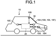
- the mobile body 10 includes an information processing device 20, a windshield 30, an output unit 10A, a camera 10B, a sensor 10C, a power control unit 10G, and a power unit 10H.
- Examples of the mobile body 10 include a vehicle, a truck, a railroad, a mobile robot, a flying body, a human being, and the like, but are not limited thereto.
- Examples of the vehicle include a motorcycle, a four-wheel automobile, a bicycle, and the like.
- the mobile body 10 may be, for example, a mobile body that travels through driving operation by a person, or may be a mobile body that can automatically travel (perform autonomous traveling) without driving operation by a person.
- the power unit 10H is a drive mechanism mounted on the mobile body 10.
- Examples of the power unit 10H include an engine, a motor, wheels, and the like.
- the communication unit 10D transmits the estimation result information to another device.
- the communication unit 10D transmits the estimation result information to another device via a communication line.
- the display 10E displays information related to the estimation result. Examples of the display 10E include a liquid crystal display (LCD), a projection device, a light, and the like.
- the speaker 10F outputs a sound indicating information related to the estimation result.
- Examples of the camera 10B include a monocular camera, a stereo camera, a fish-eye camera, an infrared camera, and the like.
- the number of cameras 10B is not limited.
- a captured image may be a color image including three channels of RGB, or may be a one-channel monochrome image expressed in gray scale.
- the camera 10B captures time-series images around the mobile body 10.
- the camera 10B outputs the time-series images by imaging a periphery of the mobile body 10 in a time-series manner, for example.
- the periphery of the mobile body 10 is, for example, a region within a predetermined range from the mobile body 10. This range is, for example, a range in which the camera 10B can perform imaging.
- the sensor 10C is a sensor that measures measurement information.
- the measurement information includes, for example, a speed of the mobile body 10, and a steering angle of a steering wheel of the mobile body 10.
- Examples of the sensor 10C include an inertial measurement unit (IMU), a speed sensor, a steering angle sensor, and the like.
- the IMU measures measurement information including triaxial acceleration and triaxial angular velocity of the mobile body 10.
- the speed sensor measures speed from a rotation amount of a tire.
- the steering angle sensor measures a steering angle of the steering wheel of the mobile body 10.
- the sensor 10C is a depth distance sensor that measures a distance to an object, such as LiDAR.
- FIG. 2 is a view illustrating an example of a functional configuration of the mobile body 10 of the first arrangement.
- the processing unit 20A, the storage unit 20B, the output unit 10A, the camera 10B, the sensor 10C, and the power control unit 10G are connected via a bus 10I.
- the power unit 10H is connected to the power control unit 10G.
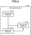
- FIG. 3 is a block diagram illustrating an example of a functional configuration of the processing unit 20A.
- the processing unit 20A includes an acquisition module 101, a detection module 102, and an estimation module 103.
- an image may include distortion due to the windshield 30.
- an image acquired by the acquisition module 101 is referred to as a distorted image.
- the detection module 102 detects a feature point from each of a plurality of acquired distorted images.
- a feature point detection method may be any detection method.
- the detection module 102 can detect a feature point by using a Harris detector.
- the detection module 102 may use a detection method in which it is considered that the images are distorted by the windshield 30.
- the detection module 102 may set a threshold to determine a feature point looser than a case where it is not considered that the images are distorted.
- the estimation module 103 estimates a position of an object captured in the images from the detected feature points. For example, from the plurality of feature points respectively detected for the plurality of distorted images, the estimation module 103 estimates and outputs a pose of the camera 10B of when the distorted images are captured, positions in three dimensions (three-dimensional position) of the feature points, and distortion maps corresponding to the distorted images.
- the pose of the camera 10B includes, for example, a position and posture of the camera 10B. For example, by minimizing an error between a detection position of a feature point, which is corrected on the basis of a distortion map, and a three-dimensional position, the estimation module 103 estimates the distortion map, the three-dimensional position, and the detection position.
- the distortion map is information that includes an amount of displacement at each two-dimensional position as distortion.
- processor used in arrangements includes, for example, a CPU, a graphical processing unit (GPU), an application specific integrated circuit (ASIC), and a programmable logic device.
- the programmable logic device include a simple programmable logic device (SPLD), a complex programmable logic device (CPLD), a field programmable gate array (FPGA), and the like.
- the processor realizes the processing unit 20A by reading and executing a program stored in the storage unit 20B.
- the program may be directly incorporated in a circuit of the processor.
- the processor realizes the processing unit 20A by reading and executing the program incorporated in the circuit.
- a part of the functions of the mobile body 10 illustrated in FIG. 2 may be provided in another device.
- a camera 10B, a sensor 10C, and the like may be mounted on a mobile body 10, and an information processing device 20 may be caused to operate as a server device installed outside the mobile body 10.
- a communication unit 10D transmits data observed by the camera 10B, the sensor 10C, and the like to the server device.
- the acquisition module 101 acquires a plurality of images photographed at different positions through the windshield 30 (Step S101). First, the acquisition module 101 acquires an image acquired by the camera 10B by imaging of the front side of the vehicle at a certain time point.
- FIG. 5 is a view illustrating an example of image distortion due to an influence of the windshield 30. As illustrated in a drawing on a left side, in a case where there is no windshield 30, an intersection 511 between a straight line connecting a three-dimensional point 501 and a center of the camera 10B, and of an image plane is an observation point.
- an image may be distorted according to a relative positional relationship between the camera 10B and the windshield 30. For example, in a case where the windshield 30 is inclined with respect to an imaging surface of the camera 10B, an image is distorted. In such a manner, an image captured through the windshield 30 has different distortion at each position on the image.
- the acquisition module 101 further acquires an image captured through the windshield 30 after the mobile body 10 is moved to a different position. By repeating such processing, the acquisition module 101 acquires a plurality of images photographed at different positions.
- the camera 10B captures images at regular time intervals in a traveling vehicle and outputs time-series images.
- distorted images are necessary in at least two different positions.
- the detection module 102 detects feature points of the plurality of distorted images acquired by the acquisition module 101 (Step S102).
- the estimation module 103 associates identical feature points among the feature points detected respectively in the plurality of distorted images (Step S103).
- the estimation module 103 performs association using a scale invariant feature transform (SIFT) feature.
- SIFT scale invariant feature transform
- An associating method is not limited to this, and may be any method.
- the estimation module 103 may use a method in which it is considered that the images are distorted by the windshield 30. For example, when a region around a feature line is divided, the estimation module 103 may set limitation to a region that is not influenced much by distortion.
- the estimation module 103 estimates an initial value of a pose of the camera 10B and initial values of three-dimensional positions of the feature points (Step S104). For example, the estimation module 103 estimates the pose of the camera 10B and the three-dimensional positions of the feature points without considering image distortion, and sets these as initial values. For the estimation of the initial values, SfM or the like may be used with the feature points, for example.
- the estimation module 103 may estimate an initial value of a pose by using sensor data detected by external another sensor (such as IMU or wheel encoder) without using a feature point for the estimation of the pose. Also, the estimation module 103 may use an image captured by another camera without the windshield 30.
- FIG. 6 to FIG. 9 are views for describing errors that may be generated due to image distortion.
- FIG. 6 to FIG. 9 an example in which one feature point corresponding to an object is imaged in two poses through the windshield 30 is illustrated.
- FIG. 6 is an example of three-dimensional reconstruction of a case where there is no windshield 30. In this case, since it is not necessary to consider image distortion, an intersection of two straight lines connecting a center of the camera 10B with observation points 611 and 612 respectively is reconstructed as a three-dimensional point 601.
- FIG. 7 is a view illustrating an example of three-dimensional reconstruction of a case where refraction of light by the windshield 30 is considered.
- a three-dimensional point 701 indicates a point reconstructed in consideration of refraction.
- FIG. 8 is a view illustrating an example in which three-dimensional reconstruction is performed without consideration of image distortion although there is the windshield 30. In this case, a wrong three-dimensional point 601 is reconstructed.
- a pose for example, in a case where the pose is estimated with a feature point as a reference without utilization of an external sensor, a pose including an error due to image distortion is estimated.
- FIG. 9 is a view illustrating an example in which image distortion is considered as image distortion flows 911 and 912 indicating deviations on images according to the present arrangement. Details of FIG. 9 will be described later.
- the estimation module 103 estimates a pose, a three-dimensional position of a feature point, and a distortion map by correcting and optimizing a detection position of a feature point by a flow indicating image distortion at each position on an image (image distortion flow) by using the estimated initial value (Step S105).
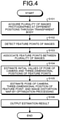
- FIG. 10 is a view for describing correction and optimization processing by an image distortion flow.
- the estimation module 103 projects a feature point i onto an image and acquires a reprojection position pij (point 1001) on the basis of a three-dimensional position of the feature point i and a pose j of the camera 10B.
- the estimation module 103 corrects a detection position qij of the feature point on the image by an image distortion flow G(qij) (image distortion flow 911) acquired from a distortion map G.
- the distortion map G can be interpreted as a function that outputs the image distortion flow corresponding to the designated detection position qij.
- the estimation module 103 minimizes the following equation (1) with a difference between a correction position qij + G(q ij ) and the reprojection position pij as a reprojection error (arrow 1011) .
- E ⁇ i j p ij ⁇ q ij + G q ij 2
- the sum in the equation (1) is calculated for a pair (i, j) of the feature point i and the pose j corresponding to the image in which the feature point i is detected.
- the equation (1) is an example of the reprojection error, and an equation other than the equation (1) may be used as long as being an error function of evaluating a difference between a correction position and a reprojection position.
- the estimation module 103 may use any method as an optimization method.
- the estimation module 103 may use nonlinear optimization by the Levenberg Marquardt (LM) method.
- LM Levenberg Marquardt
- the estimation module 103 estimates one distortion map for all images.
- a constraint term on a distortion map may be added to the error function.
- a smoothing term of a flow at an adjacent lattice point, and a bias term with displacement of a flow from a specific model as a parameter may be added to the error function.
- the estimation module 103 may estimate an initial value in consideration of image distortion. Also, although an image distortion flow to correct a detection position of a feature point on an image is estimated as a distortion map, a flow to correct a reprojection position of a three-dimensional point of a feature point may be estimated as a distortion map.
- the estimation module 103 outputs an estimation result (Step S106).
- the estimation module 103 outputs at least one of a pose, a three-dimensional position of a feature point, and a distortion map as an estimation result.
- the output distortion map can be used when image-based three-dimensional reconstruction is executed subsequently.
- the information processing device of the first arrangement estimates a pose, a three-dimensional position of a feature point, and distortion of an image by acquiring a distorted image captured through a transparent body such as a windshield, detecting a feature point from the image, and correcting and optimizing a detection position of the feature point by a distortion map.
- the distortion map is estimated together with the pose and the three-dimensional position of the feature point.
- distortion of an image due to a transparent body can be estimated as a distortion map by a flow at each position of a local image without generation of an image in which distortion is corrected.
- feature points are consistent with respect to a transparent body and a camera motion, and more accurate three-dimensional reconstruction can be realized.
- An information processing device estimates a distortion map for each of a plurality of groups into which images are classified.
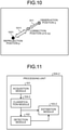
- FIG. 11 is a block diagram illustrating an example of a configuration of a processing unit 20A-2 according to the second arrangement. As illustrated in FIG. 11 , the processing unit 20A-2 includes an acquisition module 101, a detection module 102, an estimation module 103-2, and a classification module 104-2.
- the second arrangement is different from the first arrangement in a point that a function of the estimation module 103-2, and the classification module 104-2 are added. Since the other configurations and functions are similar to those in FIG. 3 that is a block diagram of the processing unit 20A according to the first arrangement, the same sign is assigned and a description thereof is omitted herein.
- the classification module 104-2 classifies a plurality of acquired images into a plurality of groups including a plurality of images having similar distortion to each other.
- a group is a set of images classified according to predetermined conditions. Images included in a group is preferably classified in such a manner as to have similar or identical distortion.
- the classification module 104-2 classifies images as follows, for example.
- the acquisition module 101 may be configured to acquire images classified into groups by an external device, or the acquisition module 101 may be configured to classify images into groups while performing acquisition thereof. In this case, it can be interpreted that the acquisition module 101 has a function of the classification module 104-2.
- the estimation module 103-2 is different from the estimation module 103 of the first arrangement in a point that a distortion map, a three-dimensional position, and a detection position are estimated for each of a plurality of groups.
- the estimation module 103-2 uses a distortion map unique for a group to which an image in which the feature point is detected belongs. As a result, the same distortion map can be estimated for each image that belongs to the group.
- the classification module 104-2 sets a group for each of the plurality of cameras 10B, and classifies images respectively acquired from the plurality of cameras 10B into corresponding groups.
- a plurality of cameras 10B (camera 10B-a and camera 10B-b) is mounted on a mobile body 10.
- right and left cameras of a stereo camera may be the camera 10B-a and the camera 10B-b, respectively.
- the camera 10B-a and the camera 10B-b may be cameras respectively mounted on a plurality of vehicles. At least one of the camera 10B-a and the camera 10B-b may be a camera fixed to a roadside.
- the classification module 104-2 classifies distorted images captured by the camera 10B-a into a group G-a, and distorted images captured by the camera 10B-b into a group G-b.
- the estimation module 103-2 estimates two distortion maps that are a distortion map M-a corresponding to the camera 10B-a and a distortion map M-b corresponding to the camera 10B-b.
- images are captured by the cameras 10B respectively through different windshields 30. According to the present arrangement, it is possible to estimate a pose and a three-dimensional position of a feature point in consideration of an influence of image distortion by each windshield 30.
- the classification module 104-2 may classify images before and after the change into different groups. For example, the classification module 104-2 detects a change in a position of a specific object (such as hood of a vehicle) imaged in an image by an analysis or the like of the image, and classifies images before and after the change into different groups in a case where the position changes.
- a specific object such as hood of a vehicle
- the classification module 104-2 classifies a plurality of images acquired by one camera 10B on the basis of a traveling place of the mobile body 10. For example, with a traveling distance as a condition, the classification module 104-2 may perform classification into a new group every time traveling is performed for a certain distance (such as 100 m). In this case, the estimation module 103-2 estimates a distortion map for each traveling section.
- the classification module 104-2 may classify images with acquisition time as a condition. For example, the classification module 104-2 classifies the acquired images into different groups at regular intervals (such as several seconds). In this case, the estimation module 103-2 estimates a distortion map at regular intervals.
- the classification module 104-2 may classify images with a plurality of predetermined periods of time (such as morning, noon, and evening) as conditions. As a result, the estimation module 103-2 can estimate a distortion map for each period of time even when a state of a windshield 30 changes due to changes in an outside air temperature and weather and image distortion changes.
- the classification module 104-2 may classify images with a state of the windshield 30 as a condition. For example, the classification module 104-2 may perform classification into groups according to transparency and color of the windshield 30. For example, the classification module 104-2 detects changes in the transparency and color of the windshield 30 by analyzing acquired images, and classifies the images according to a detection result.
- FIG. 12 is a flowchart illustrating an example of estimation processing in the second arrangement.
- Step S201 is processing similar to that in Step S101 in the information processing device 20 according to the first arrangement.
- the classification module 104-2 classifies a plurality of acquired images into groups (Step S202). Step S203 to Step S207 thereafter are different from Step S102 to Step S106 in the information processing device 20 according to the first arrangement in a point of being executed for each group.
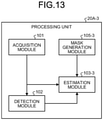
- An information processing device generates a mask indicating a region in which a distortion map is estimated, corrects a feature point according to the generated mask, and estimates a distortion map.
- FIG. 13 is a block diagram illustrating an example of a configuration of a processing unit 20A-3 according to the third arrangement. As illustrated in FIG. 13 , the processing unit 20A-3 includes an acquisition module 101, a detection module 102, an estimation module 103-3, and a mask generation module 105-3.
- the third arrangement is different from the first arrangement in a point that a function of the estimation module 103-3 and the mask generation module 105-3 are added. Since the other configurations and functions are similar to those in FIG. 3 that is a block diagram of the processing unit 20A according to the first arrangement, the same sign is assigned and a description thereof is omitted herein.
- the mask generation module 105-3 generates a mask indicating a region in which a distortion map is generated.
- the region indicated by the mask is preferably a region where an image distortion flow needs to be estimated or can be estimated. A specific example of a mask will be described later.
- the mask generation module 105-3 may generate a mask for each camera 10B, or may generate a mask for each image.
- the mask may be expressed by a binary indicating whether to estimate a distortion map, or may be expressed by a continuous value such as priority in estimation.
- the mask generation module 105-3 designates a region in which a distortion map is estimated in an image, and generates a mask indicating a region in which a distortion map is not estimated in other regions.
- the estimation module 103-3 corrects a feature point on the basis of the generated mask and estimates a distortion map. Unlike the first arrangement, the estimation module 103-3 of the present arrangement does not correct positions of all feature points, and corrects only a feature point included in the region indicated by the mask. For example, the estimation module 103-3 estimates an image distortion flow and corrects a position of a feature point in the region indicated by the mask. The estimation module 103-3 does not estimate a flow in other regions on the assumption that no image distortion is generated, and uses a position of the detected feature point as it is for evaluation of a reprojection error.
- each feature point may be weighted according to the continuous value.
- the estimation module 103-3 may use a function G modified in such a manner as to use information of a feature point weighted according to the continuous value.
- the mask generation module 105-3 can generate a mask by the following methods, for example.
- (M1) Details of (M1) will be described. There is a case where a windshield 30 does not cover an entire camera 10B and only a part of an image captured by the camera 10B is captured through the windshield 30. In such a case, the mask generation module 105-3 generates a mask indicating a region of an image captured through the windshield 30.
- the mask generation module 105-3 generates a mask indicating only a region of the window. For example, the mask generation module 105-3 can determine whether a region in the image is the region of the window by analyzing the image.
- the mask generation module 105-3 may respectively generate different masks for a plurality of cameras 10B. As a result, appropriate estimation processing can be performed even in a configuration in which a camera 10B that images an object through a windshield 30 and a camera 10B that images the object without the windshield 30 are mixed.
- a distortion map of a part of an image can be estimated by generation of a mask indicating a region imaged through a windshield 30 in the image. That is, even in a case where a windshield 30 appears in a part of an image, highly accurate three-dimensional reconstruction can be performed.
- a region including a specific object is, for example, a region including an object other than a mobile body (another mobile body different from a mobile body 10).
- (M2) can be also interpreted to "generate a mask indicating a region that does not include a specific object in an image" with a mobile body as the specific object.
- the estimation module 103-3 projects each three-dimensional point in a three-dimensional space onto a different position in an image. Here, it is assumed that the three-dimensional point does not move while images at different positions are captured.
- the mask generation module 105-3 generates a mask indicating a region what is other than the mobile body. For estimation of a distortion map, the estimation module 103-3 does not use a feature point in a region corresponding to the mobile body.
- an object to be excluded may be an object such as a repeating structure in which association of a feature point easily fails.
- the object to be excluded can be detected, for example, by utilization of detection technology such as semantic segmentation and specific object recognition.
- the mask generation module 105-3 generates, as a mask, a region including more feature points than other regions, in other words, a region in which feature points can be sufficiently detected.
- the estimation module 103-3 estimates a distortion map by totally optimizing distortion flows of feature points detected at the same position in a plurality of images. However, when the number of feature points is small in a range in which flows are estimated, estimation accuracy deteriorates. Thus, it is preferable to estimate a distortion map only in a region where estimation accuracy is guaranteed by using a mask.
- a region including more feature points than other regions is, for example, a region in which the number of feature points or density of feature points exceeds a threshold.
- the mask generation module 105-3 calculates the number of feature points or the density of feature points, and generates a mask indicating a region in which the calculated value exceeds the threshold.
- FIG. 14 is a flowchart illustrating an example of estimation processing in the third arrangement.
- Step S301 and S302 are processing similar to Step S101 and S102 in the information processing device 20 according to the first arrangement.
- the mask generation module 105-3 generates a mask (Step S303).
- Step S304 and S305 are processing similar to Step S103 and S104 in the information processing device 20 according to the first arrangement.
- the estimation module 103-3 performs estimation by using the mask (Step S306). For example, the estimation module 103-3 corrects only a feature point included in a region indicated by the mask, and estimates a flow. In a case where the mask is expressed by a continuous value, the estimation module 103-3 may perform estimation while weighting each feature point according to the continuous value.
- Step S307 is processing similar to that in Step S106 in the information processing device 20 according to the first arrangement.
- a feature point is corrected with a region where a distortion map is estimated being limited by a mask, whereby it becomes possible to perform highly accurate three-dimensional reconstruction in which an influence of distortion of the windshield 30 is removed.
- a position or the like of an object can be estimated with higher accuracy.
- a program executed in the information processing device according to each of the first to third arrangements is previously installed in a ROM 52 or the like and provided.
- a program executed in the information processing device may be recorded, as a file in an installable format or an executable format, into a computer-readable recording medium such as a compact disk read only memory (CD-ROM), a flexible disk (FD), a compact disk recordable (CD-R), or a digital versatile disk (DVD), and provided as a computer program product.
- a computer-readable recording medium such as a compact disk read only memory (CD-ROM), a flexible disk (FD), a compact disk recordable (CD-R), or a digital versatile disk (DVD)
- a program executed in the information processing device according to each of the first to third arrangements may be stored on a computer connected to a network such as the Internet and may be provided by being downloaded via the network. Also, a program executed in the information processing device according to each of the first to third arrangements may be provided or distributed via a network such as the Internet.
- a program executed in the information processing device may cause a computer to function as each unit of the information processing device described above.
- a CPU 51 can read a program from a computer-readable storage medium onto a main storage device and perform execution thereof.
Landscapes
- Engineering & Computer Science (AREA)
- Theoretical Computer Science (AREA)
- General Physics & Mathematics (AREA)
- Physics & Mathematics (AREA)
- Computer Vision & Pattern Recognition (AREA)
- Data Mining & Analysis (AREA)
- General Engineering & Computer Science (AREA)
- Multimedia (AREA)
- Evolutionary Computation (AREA)
- Bioinformatics & Computational Biology (AREA)
- Bioinformatics & Cheminformatics (AREA)
- Artificial Intelligence (AREA)
- Life Sciences & Earth Sciences (AREA)
- Evolutionary Biology (AREA)
- Automation & Control Theory (AREA)
- Human Computer Interaction (AREA)
- Transportation (AREA)
- Mechanical Engineering (AREA)
- Image Analysis (AREA)
- Traffic Control Systems (AREA)
Applications Claiming Priority (1)
| Application Number | Priority Date | Filing Date | Title |
|---|---|---|---|
| JP2020129662A JP7383584B2 (ja) | 2020-07-30 | 2020-07-30 | 情報処理装置、情報処理方法、プログラムおよび車両制御システム |
Publications (1)
| Publication Number | Publication Date |
|---|---|
| EP3945455A1 true EP3945455A1 (fr) | 2022-02-02 |
Family
ID=74856710
Family Applications (1)
| Application Number | Title | Priority Date | Filing Date |
|---|---|---|---|
| EP21160377.4A Pending EP3945455A1 (fr) | 2020-07-30 | 2021-03-03 | Dispositif de traitement d'informations, procédé de traitement d'informations, support lisible par ordinateur et système de commande de véhicule |
Country Status (4)
| Country | Link |
|---|---|
| US (1) | US11897517B2 (fr) |
| EP (1) | EP3945455A1 (fr) |
| JP (1) | JP7383584B2 (fr) |
| CN (1) | CN114092548B (fr) |
Families Citing this family (4)
| Publication number | Priority date | Publication date | Assignee | Title |
|---|---|---|---|---|
| EP4016444B1 (fr) * | 2020-12-15 | 2025-06-18 | Continental Autonomous Mobility Germany GmbH | Procédé de rectification d'images et/ou de points d'image, système par caméra et véhicule |
| US20230136492A1 (en) * | 2021-09-10 | 2023-05-04 | Samsung Electronics Co., Ltd. | Method and apparatus for estimating position of moving object |
| US12190545B2 (en) | 2022-10-26 | 2025-01-07 | Chengdu Qinchuan Iot Technology Co., Ltd. | Intelligent manufacturing industrial internet of things with front split service platform, control method and medium thereof |
| DE102024002265A1 (de) | 2024-07-11 | 2025-09-25 | Mercedes-Benz Group AG | Verfahren zur Erkennung von Verzerrungen einer Fahrzeugscheibe sowie Erkennungssystem |
Citations (2)
| Publication number | Priority date | Publication date | Assignee | Title |
|---|---|---|---|---|
| WO2017057057A1 (fr) * | 2015-09-30 | 2017-04-06 | ソニー株式会社 | Dispositif de traitement d'image, procédé de traitement d'image et programme |
| WO2019171984A1 (fr) * | 2018-03-08 | 2019-09-12 | ソニー株式会社 | Dispositif de traitement de signal, procédé de traitement de signal et programme |
Family Cites Families (6)
| Publication number | Priority date | Publication date | Assignee | Title |
|---|---|---|---|---|
| US5825483A (en) | 1995-12-19 | 1998-10-20 | Cognex Corporation | Multiple field of view calibration plate having a reqular array of features for use in semiconductor manufacturing |
| US9509979B2 (en) | 2013-11-26 | 2016-11-29 | Mobileye Vision Technologies Ltd. | Stereo auto-calibration from structure-from-motion |
| US9881235B1 (en) * | 2014-11-21 | 2018-01-30 | Mahmoud Narimanzadeh | System, apparatus, and method for determining physical dimensions in digital images |
| JP6685836B2 (ja) * | 2016-05-30 | 2020-04-22 | 株式会社東芝 | 情報処理装置、および、情報処理方法 |
| JP6975003B2 (ja) | 2017-09-29 | 2021-12-01 | 株式会社デンソー | 周辺監視装置およびその校正方法 |
| CN110296691B (zh) | 2019-06-28 | 2020-09-22 | 上海大学 | 融合imu标定的双目立体视觉测量方法与系统 |
-
2020
- 2020-07-30 JP JP2020129662A patent/JP7383584B2/ja active Active
-
2021
- 2021-03-03 EP EP21160377.4A patent/EP3945455A1/fr active Pending
- 2021-03-03 US US17/190,681 patent/US11897517B2/en active Active
- 2021-03-04 CN CN202110237636.8A patent/CN114092548B/zh active Active
Patent Citations (2)
| Publication number | Priority date | Publication date | Assignee | Title |
|---|---|---|---|---|
| WO2017057057A1 (fr) * | 2015-09-30 | 2017-04-06 | ソニー株式会社 | Dispositif de traitement d'image, procédé de traitement d'image et programme |
| WO2019171984A1 (fr) * | 2018-03-08 | 2019-09-12 | ソニー株式会社 | Dispositif de traitement de signal, procédé de traitement de signal et programme |
Also Published As
| Publication number | Publication date |
|---|---|
| JP2022026277A (ja) | 2022-02-10 |
| CN114092548B (zh) | 2025-05-13 |
| US11897517B2 (en) | 2024-02-13 |
| JP7383584B2 (ja) | 2023-11-20 |
| CN114092548A (zh) | 2022-02-25 |
| US20220032969A1 (en) | 2022-02-03 |
Similar Documents
| Publication | Publication Date | Title |
|---|---|---|
| US11897517B2 (en) | Information processing device, information processing method, computer program product, and vehicle control system | |
| US12114056B2 (en) | Cross field of view for autonomous vehicle systems | |
| US10949684B2 (en) | Vehicle image verification | |
| US11657604B2 (en) | Systems and methods for estimating future paths | |
| US11620837B2 (en) | Systems and methods for augmenting upright object detection | |
| CN111448478B (zh) | 用于基于障碍物检测校正高清地图的系统和方法 | |
| EP3264367B1 (fr) | Appareil et procédé de production d'images et support d'enregistrement | |
| WO2020185489A1 (fr) | Validation de capteur à l'aide d'informations de segmentation sémantique | |
| JP2021530049A (ja) | センサ較正 | |
| CN114495064A (zh) | 一种基于单目深度估计的车辆周围障碍物预警方法 | |
| WO2006121088A1 (fr) | Dispositif de traitement d’images, procede de traitement d’images et programme de traitement d’images | |
| US20230286548A1 (en) | Electronic instrument, movable apparatus, distance calculation method, and storage medium | |
| EP3364336B1 (fr) | Procédé et appareil permettant d'estimer la distance jusqu'à un objet mobile | |
| US12106492B2 (en) | Computer vision system for object tracking and time-to-collision | |
| CN111539279A (zh) | 道路限高高度检测方法、装置、设备及存储介质 | |
| US11919508B2 (en) | Computer vision system for object tracking and time-to-collision | |
| US11893799B2 (en) | Computer vision system for object tracking and time-to-collision | |
| US12579672B2 (en) | Stereo vision-based height clearance detection | |
| EP4195151A2 (fr) | Système de vision par ordinateur pour suivi d'objets et temps de collision | |
| Xiao et al. | Infrastructure-Guided Connectivity-Enhanced Road Crack Detection and Estimation | |
| JP2025157800A (ja) | 学習システム及び学習方法 | |
| CN119889040A (zh) | 一种车位检测方法与一种车位检测系统 |
Legal Events
| Date | Code | Title | Description |
|---|---|---|---|
| PUAI | Public reference made under article 153(3) epc to a published international application that has entered the european phase |
Free format text: ORIGINAL CODE: 0009012 |
|
| STAA | Information on the status of an ep patent application or granted ep patent |
Free format text: STATUS: REQUEST FOR EXAMINATION WAS MADE |
|
| 17P | Request for examination filed |
Effective date: 20210303 |
|
| AK | Designated contracting states |
Kind code of ref document: A1 Designated state(s): AL AT BE BG CH CY CZ DE DK EE ES FI FR GB GR HR HU IE IS IT LI LT LU LV MC MK MT NL NO PL PT RO RS SE SI SK SM TR |
|
| STAA | Information on the status of an ep patent application or granted ep patent |
Free format text: STATUS: EXAMINATION IS IN PROGRESS |
|
| 17Q | First examination report despatched |
Effective date: 20240517 |